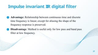
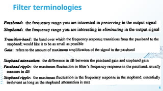
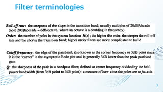
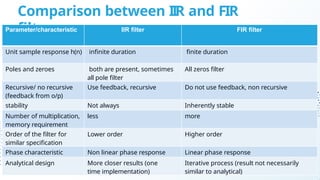
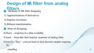
Chapter 4 discusses filter design techniques, including definitions, types, and terminologies of filters, particularly focusing on digital filters. It highlights the advantages of digital filters over analog filters, including reprogrammability and stability, and details the design methods for Infinite Impulse Response (IIR) and Finite Impulse Response (FIR) filters. The chapter further elaborates on techniques such as approximations of derivatives, impulse invariance, and bilinear transformation for designing IIR filters from analog counterparts.


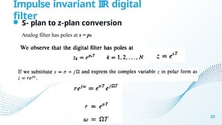
![IIR filter design by Approximations of derivatives
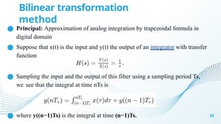
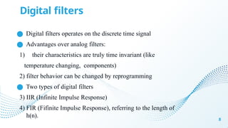
● Simplest method for converting an analog filter into a digital filter.
● Concept : which approximate the differential equation(analog domain)
by
an equivalent difference equation(digital domain).
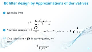
● For the derivative dy(t)/dt at a time t = nT we substitute the
backward difference [y[n]-y[n-1]]/T.
15
d y
( t )
dt
y ( n ) y ( n 1 )
T
t n T
Where T represents the sampling interval and y(n) = y(nT).](https://image.slidesharecdn.com/b69a5fb5e7674483bdd8806177e87b99-241015204404-578ae98e/85/Filter-Design-techniques-with-digital-signal-processing-pptx-15-320.jpg)
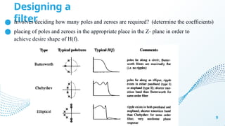
![IIR filter design by Approximations of derivatives
● analogue differentiator with output dy(t)/dt has the system function H(s) = s
● digital system that produces the output [y(n)-y(n-1)]/T has the system function
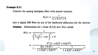
H(z) = (1 – z-1)/T
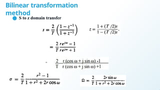
● S to z
domain
● The second derivative d2y(t)/dt2 is replaced by the second difference which is
given by
16
1 z1
s
T
T 2
dt 2
d2
y(t)
y(n) 2y(n 1) y(n 2)
T
T2
s2
1 2z1
z2
1 z1
2](https://image.slidesharecdn.com/b69a5fb5e7674483bdd8806177e87b99-241015204404-578ae98e/85/Filter-Design-techniques-with-digital-signal-processing-pptx-16-320.jpg)