Downloaded 345 times
![Filter Design by Windowing
• Simplest way of designing FIR filters
• Method is all discrete-time no continuous-time involved
• Start with ideal frequency response
∞
π
1
jω
− jω n
Hd e = ∑ hd [n]e
hd [n] =
Hd e jω e jωndω
2π −∫π
n = −∞
( )
( )
• Choose ideal frequency response as desired response
• Most ideal impulse responses are of infinite length
• The easiest way to obtain a causal FIR filter from ideal is
hd [n] 0 ≤ n ≤ M
h[n] =
else
0
• More generally
h[n] = hd [n]w[n]
where
1 0 ≤ n ≤ M
w[n] =
else
0](https://image.slidesharecdn.com/firfilter-140131234213-phpapp02/75/Fir-filter_utkarsh_kulshrestha-15-2048.jpg)
![Properties of Windows
• Prefer windows that concentrate around DC in frequency
– Less distortion, closer approximation
• Prefer window that has minimal span in time
– Less coefficient in designed filter, computationally efficient
• So we want concentration in time and in frequency
– Contradictory requirements
• Example: Rectangular window
( ) = ∑e
We
jω
M
n=0
− jω n
1 − e − jω ( M + 1 )
sin[ ω(M + 1) / 2]
=
= e − jωM / 2
sin[ ω / 2]
1 − e − jω
351M Digital Signal Processing](https://image.slidesharecdn.com/firfilter-140131234213-phpapp02/75/Fir-filter_utkarsh_kulshrestha-16-2048.jpg)
![Rectangular Window
• Narrowest main lob
– 4π/(M+1)
– Sharpest transitions at
discontinuities in
frequency
• Large side lobs
– -13 dB
– Large oscillation
around discontinuities
• Simplest window
possible
0≤n≤M
else
0
[n] = 1
w
](https://image.slidesharecdn.com/firfilter-140131234213-phpapp02/75/Fir-filter_utkarsh_kulshrestha-17-2048.jpg)
![Bartlett (Triangular) Window
• Medium main lob
– 8π/M
• Side lobs
– -25 dB
• Hamming window
performs better
• Simple equation
0 ≤ n ≤ M/2
2n / M
w[n] = 2 − 2n / M M / 2 ≤ n ≤ M
0
else
18](https://image.slidesharecdn.com/firfilter-140131234213-phpapp02/75/Fir-filter_utkarsh_kulshrestha-18-2048.jpg)
![Hanning Window
• Medium main lob
– 8π/M
• Side lobs
– -31 dB
• Hamming window
performs better
• Same complexity as
Hamming
1
2πn
1 − cos
0 ≤ n ≤ M
w[n] = 2
M
0
else
](https://image.slidesharecdn.com/firfilter-140131234213-phpapp02/75/Fir-filter_utkarsh_kulshrestha-19-2048.jpg)
![Hamming Window
• Medium main lob
– 8π/M
• Good side lobs
– -41 dB
• Simpler than Blackman
2πn
0.54 − 0.46 cos
0≤n≤M
w[n] =
M
0
else
](https://image.slidesharecdn.com/firfilter-140131234213-phpapp02/75/Fir-filter_utkarsh_kulshrestha-20-2048.jpg)
![Kaiser Window Filter Design Method
• Parameterized equation
forming a set of windows
– Parameter to change mainlob width and side-lob area
trade-off
w[ n] = {I ( Beta) | I (alpha ), | n |<= M − 1 2
0, otherwise
– I0(.) represents zeroth-order
modified Bessel function of 1st
kind
21](https://image.slidesharecdn.com/firfilter-140131234213-phpapp02/75/Fir-filter_utkarsh_kulshrestha-21-2048.jpg)
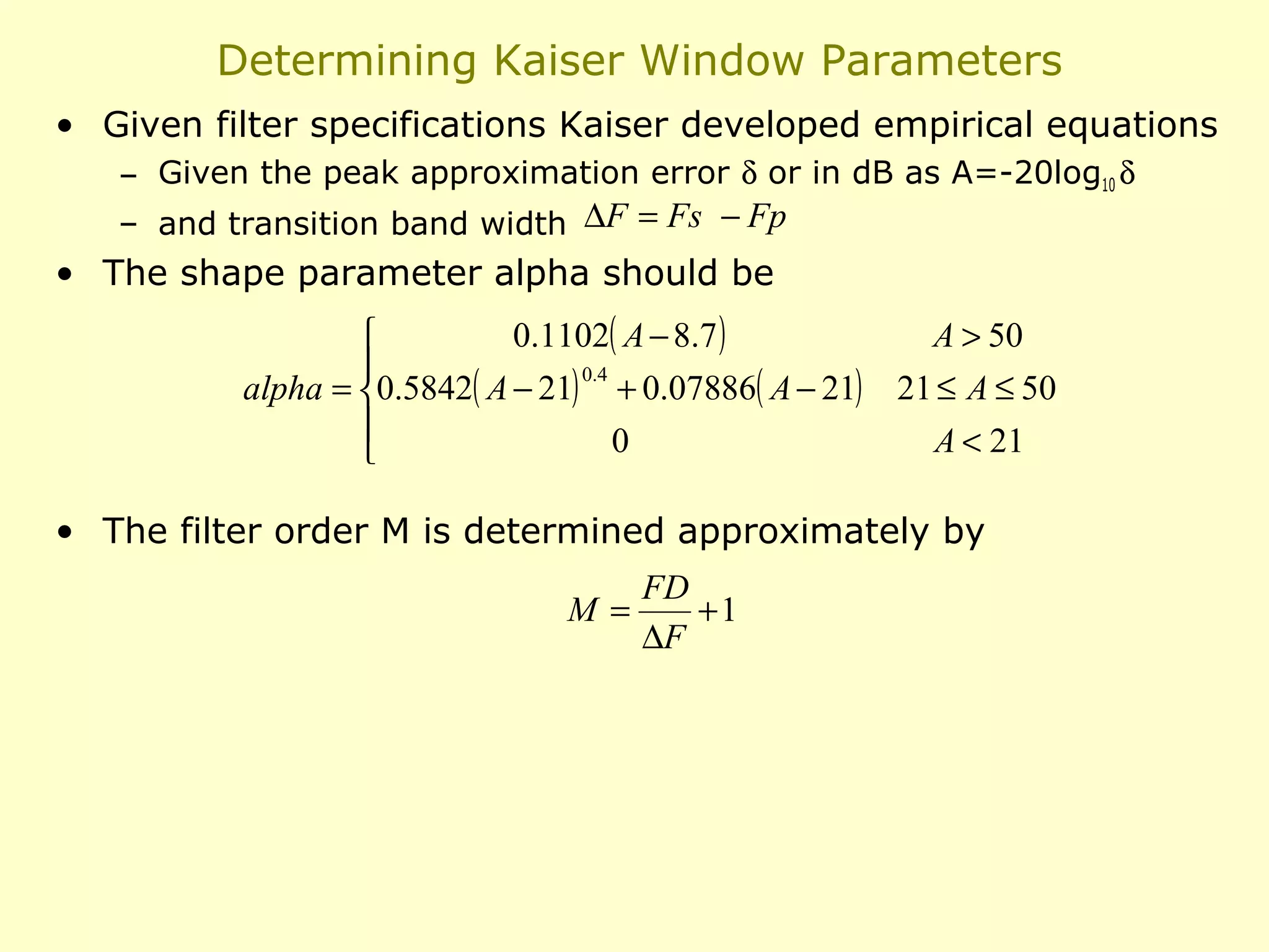
![Example: Kaiser Window Design of a Lowpass Filter
• Specifications ωp = 0.4π, ωp = 0.6π, δ1 = 0.01, δ2 = 0.001
• Window design methods assume δ1 = δ2 = 0.001
• Determine cut-off frequency
– Due to the symmetry we can choose it to be ωc = 0.5π
• Compute
∆ω = ωs − ωp = 0.2π
A = −20 log10 δ = 60
• And Kaiser window parameters
alpha = 5.653
M = 37
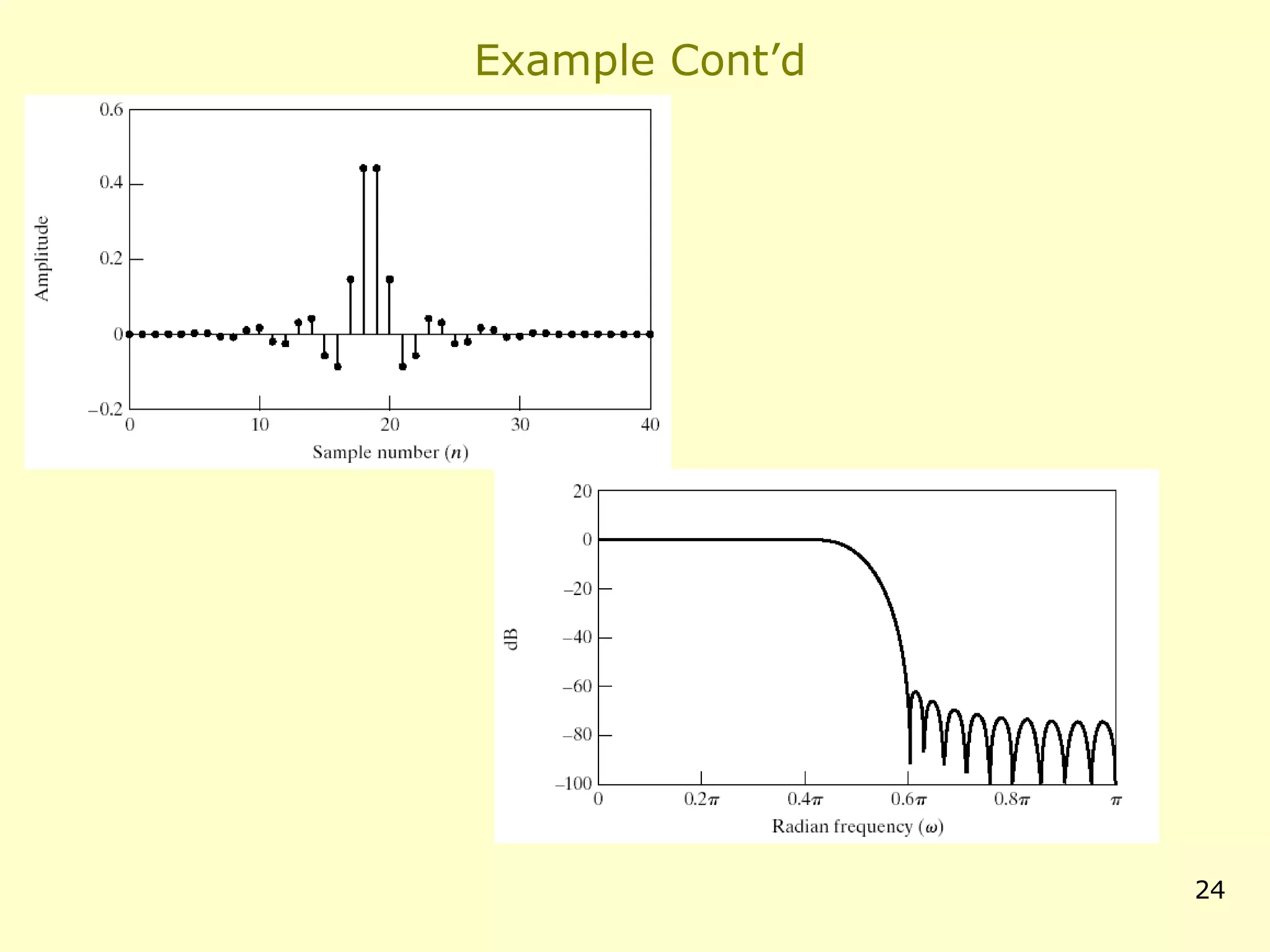
• Then the impulse response is given as
2
n − 18.5
I0 5.653 1 −
18.5
h[n] = sin[0.5π(n − 18.5) ]
π(n − 18.5)
I0 (5.653)
0
0≤n≤M
else](https://image.slidesharecdn.com/firfilter-140131234213-phpapp02/75/Fir-filter_utkarsh_kulshrestha-23-2048.jpg)
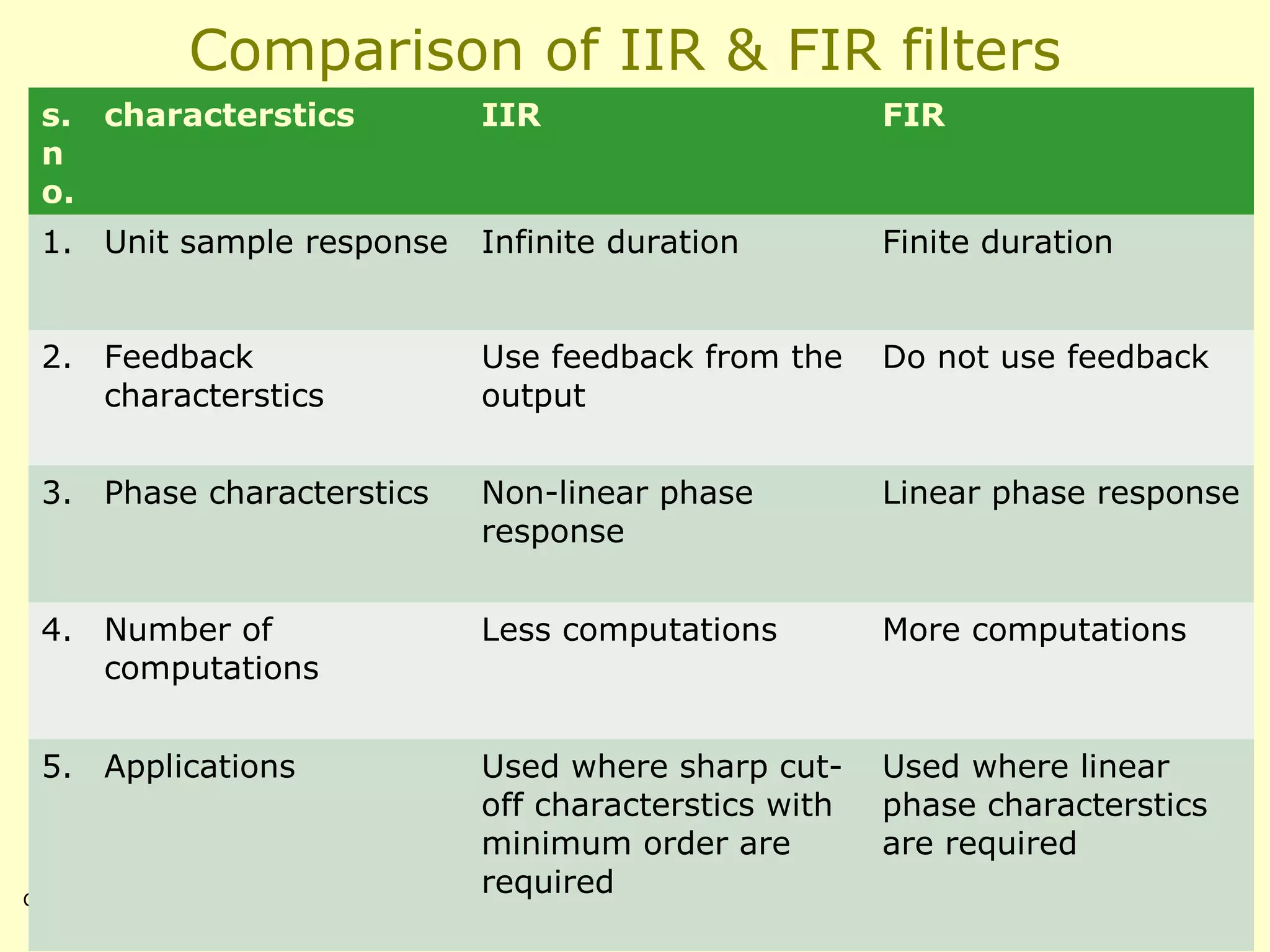

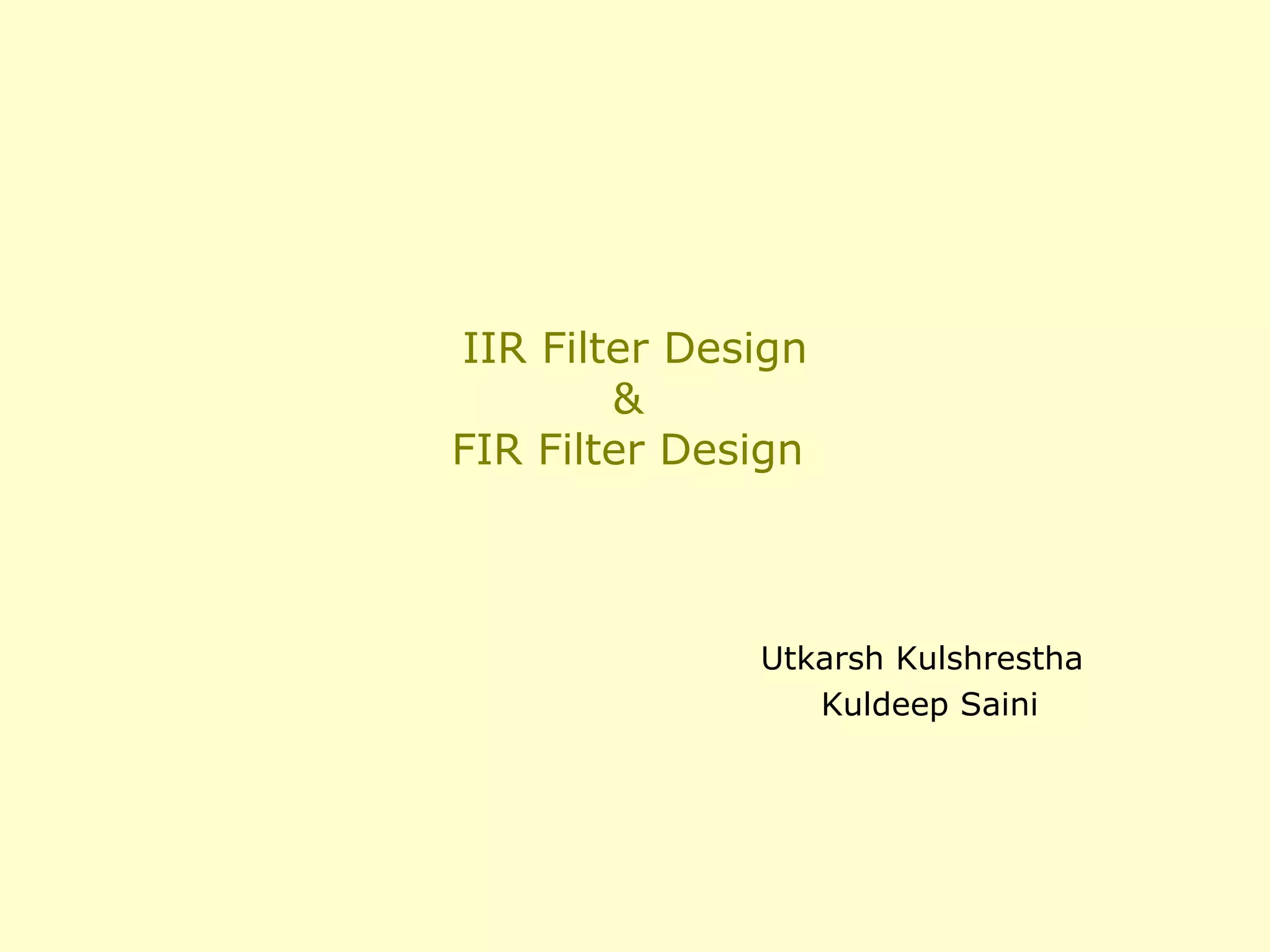
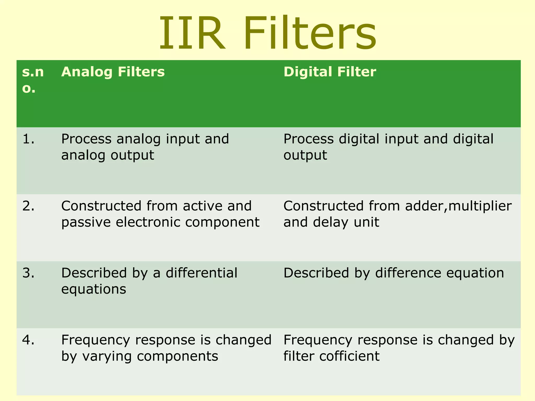
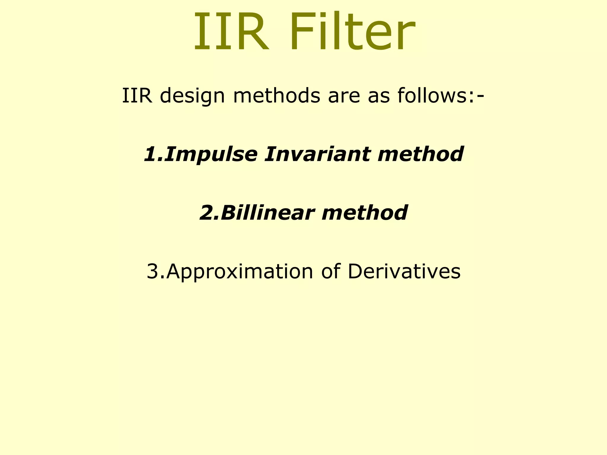
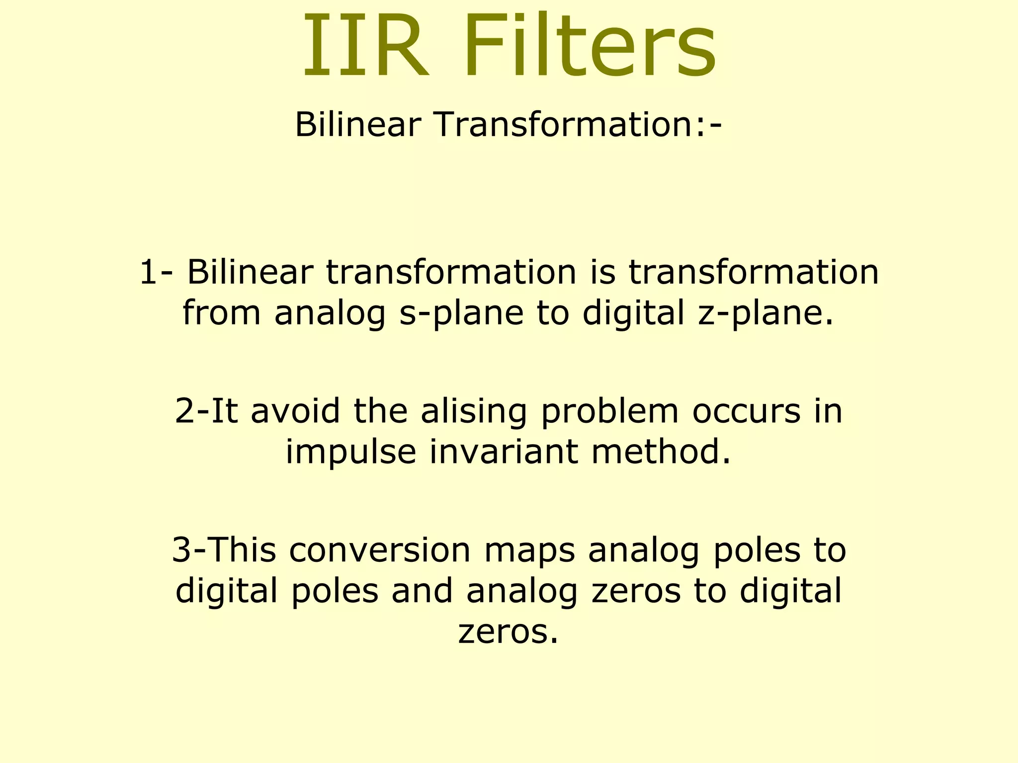
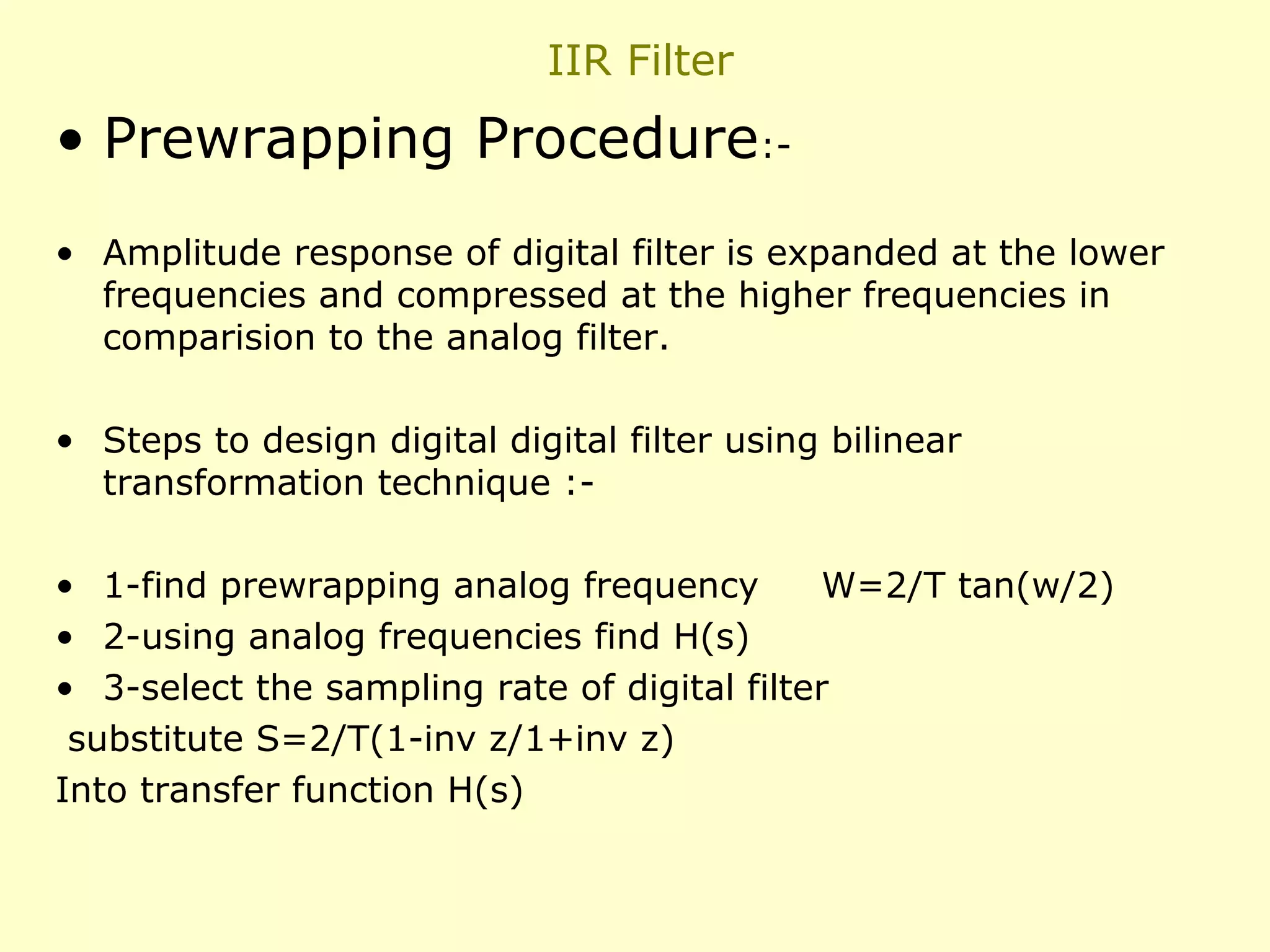
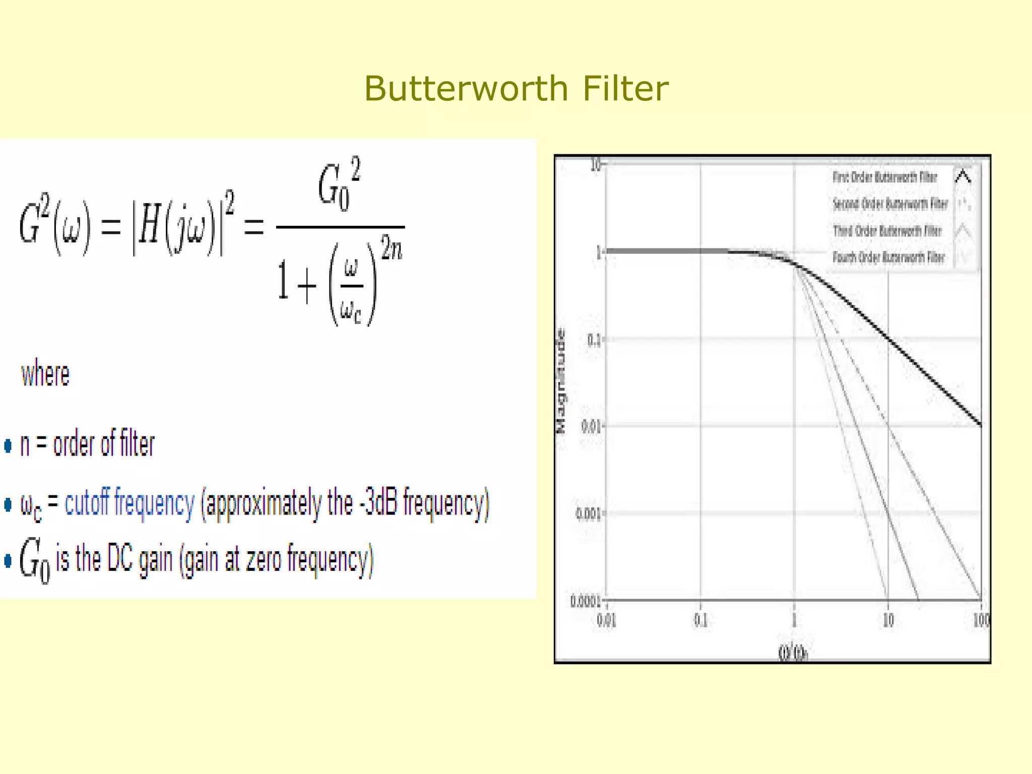
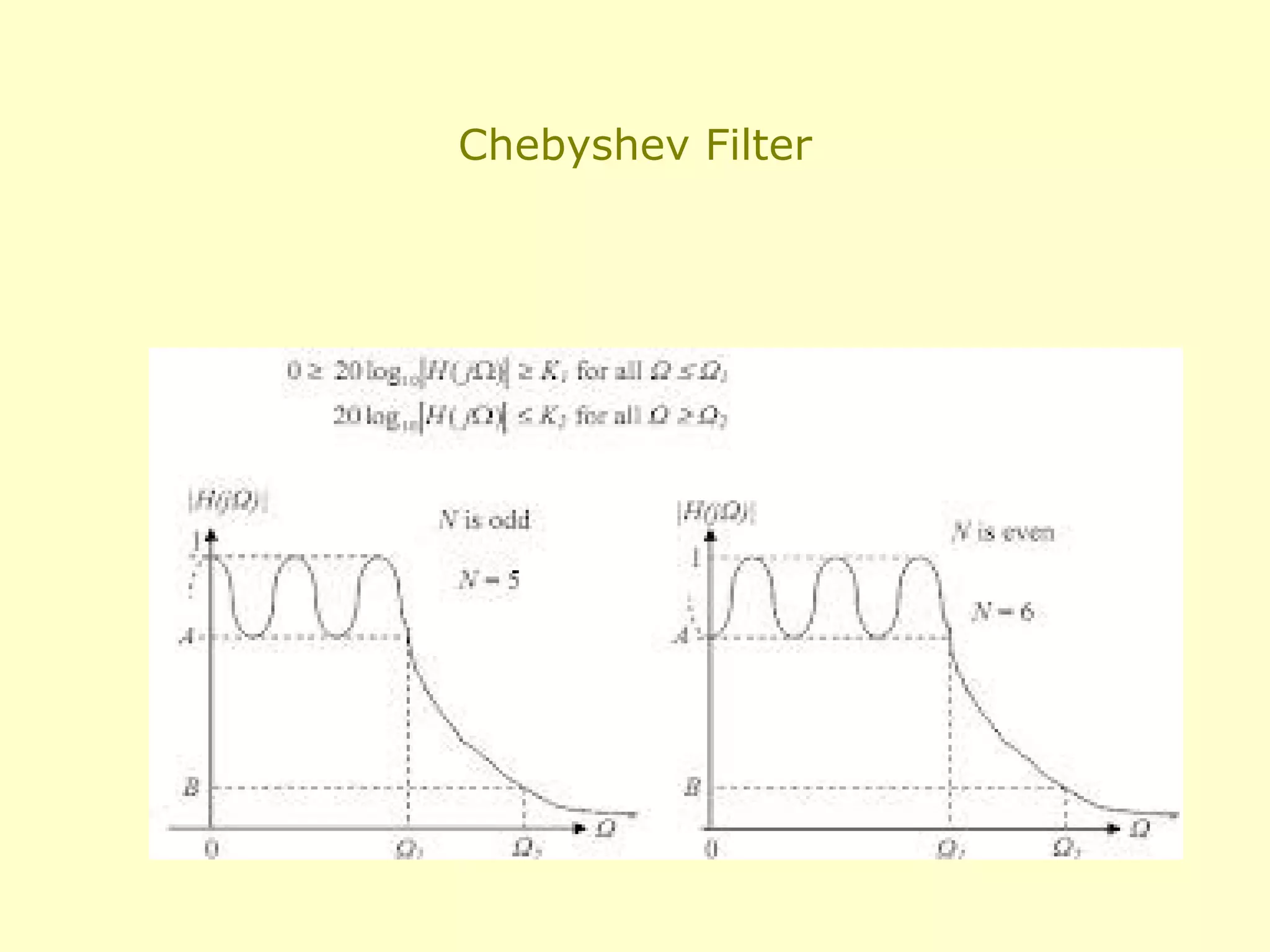
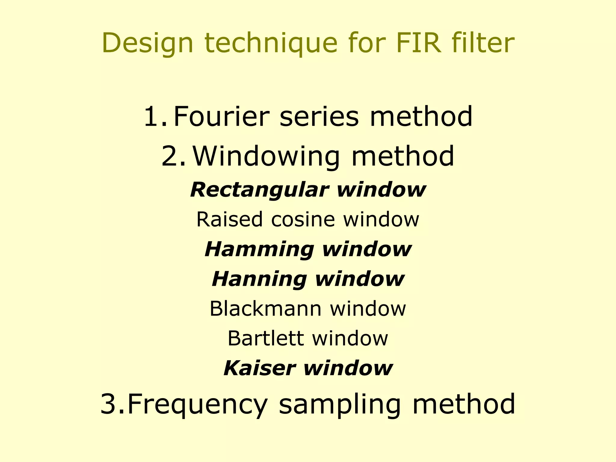
This document discusses the design of IIR and FIR filters. IIR (Infinite Impulse Response) filters are analog filters that use feedback and have non-linear phase responses. Common IIR design methods are impulse invariant, bilinear transformation, and approximation of derivatives. FIR (Finite Impulse Response) filters are digital filters with no feedback and linear phase responses. FIR filters are designed using windowing methods like rectangular, Hamming, and Kaiser windows which concentrate the filter response around the desired frequencies. IIR filters require less computation but FIR filters are required where linear phase response is needed such as data transmission and speech processing.