Download to read offline

![5
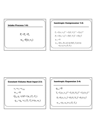
Constant Volume Heat Rejection 4-5:
5 4 1 B D C
v = v = v = v
4 -5
w = 0
4 -5 o u t v 5 4 5 4 v 1 4
q = q = c (T -T )= (u -u )= c (T -T )
Blow Down
Exhaust Stroke 5-6:
5 6 0
P =P =P
5-6 0 6 5 0 6 1
w =P (v -v )=P (v -v )
Thermal Efficiency
z From Definition and Previous Process Eqns:
[ ]
t, net in out in
OTTO
v 4 1 v 3 2
η = w / q =1-( q / q )
=1- c (T -T )/c (T -T )
( )
k-1
t, 1 2
OTTO
η =1- 1/ v /v
k-1
t, c
OTTO
η =1-(1/r )
By using Isentropic Expansion and Compression Eqns:
(cont.) Thermal Efficiency
z Note: Thermal Efficiency and Work Output/cycle
t, c
OTTO
c BDC TDC
η =Function(r Only)
r compression ratio only =V /V
=
Higher Compression Ratio is Win/Win.
Higher Efficiency and Higher Power](https://image.slidesharecdn.com/4enginecyclesanalysis-210520170437/85/Engine-Cycles-Analysis-5-320.jpg)
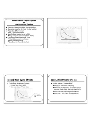

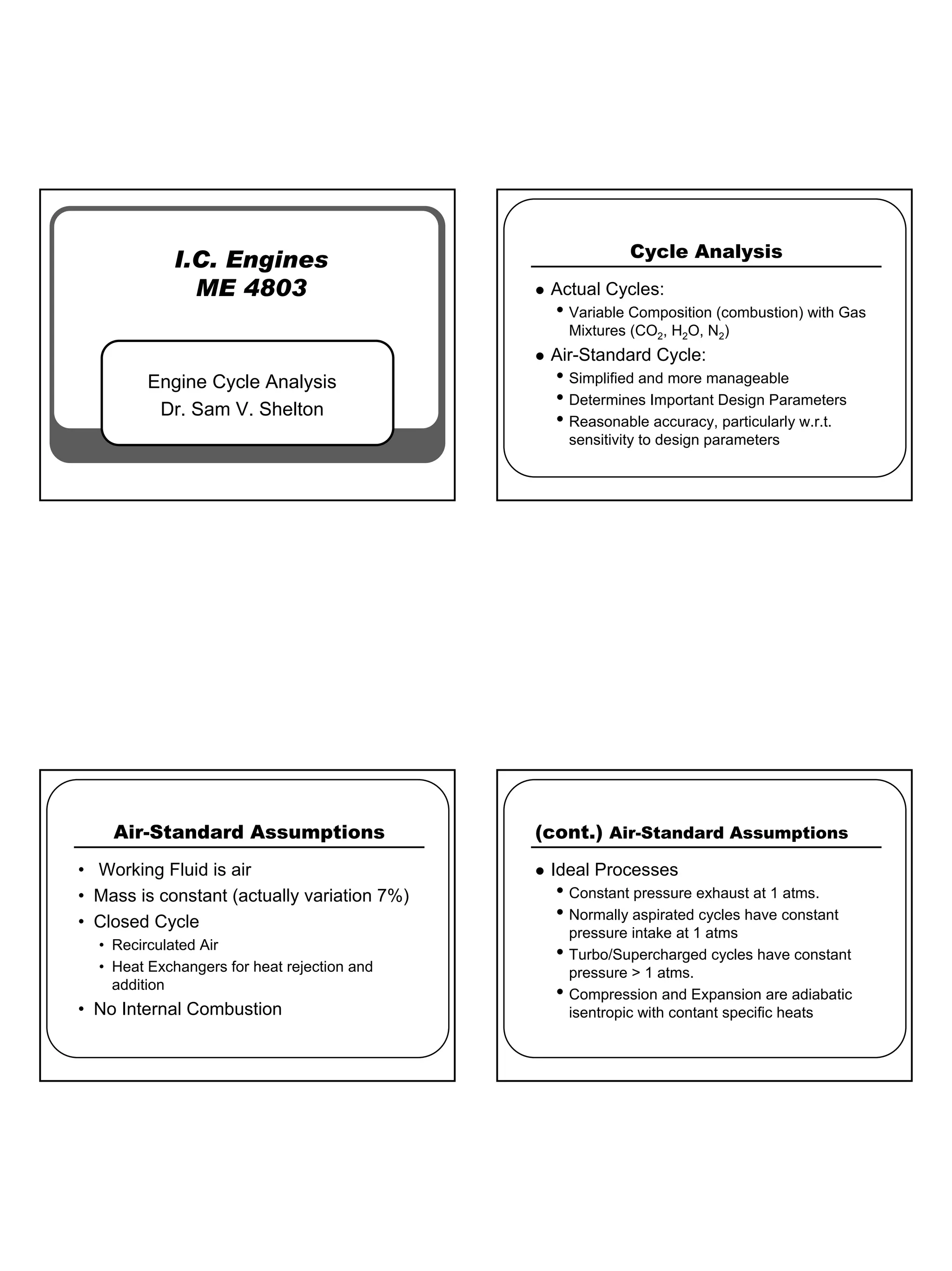
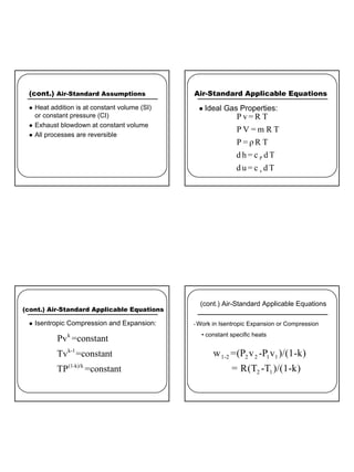
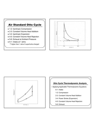
This document discusses the assumptions and equations used in air-standard cycle analysis of internal combustion engines. It covers: - The assumptions of the ideal air-standard cycle, including constant specific heats, reversible processes, and no combustion. - The relevant thermodynamic equations for analyzing the Otto cycle of intake, compression, combustion, expansion, exhaust. - How real engine cycles differ from the ideal cycle assumptions due to varying composition and properties during combustion, finite combustion duration, valve overlap effects. - How to account for pump work from intake/exhaust pressures and residual exhaust gases in the clearance volume.


