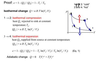
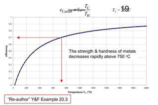
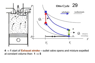
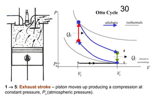
Recognize numerous types of heat exchangers, and classify them.
Develop an awareness of fouling on surfaces, and determine the overall heat transfer coefficient for a heat exchanger.
Perform a general energy analysis on heat exchangers.
Obtain a relation for the logarithmic mean temperature difference for use in the LMTD method, and modify it for different types of heat exchangers using the correction factor.
Develop relations for effectiveness, and analyze heat exchangers when outlet temperatures are not known using the effectiveness-NTU method.
Know the primary considerations in the selection of heat exchangers.
The presentation is about the fuels used in the Thermal Power Plants and the combustion taking place in large pulverised coal boilers. The calculations about the Air requirements for complete combustion of fuels in the boilers.
introduction of VARS,refrigrants properties,cop,practical VARS ,
Simple VARS,advantages of VARS,comparison of vars with vcrs,Refrences of VARS,Refrigration cycles,economical system,absorbent properties
introduction of VARS,refrigrants properties,cop,practical VARS ,
Simple VARS,advantages of VARS,comparison of vars with vcrs,Refrences of VARS,Refrigration cycles,economical system,absorbent properties
Experimental Investigation of Performance, Combustion and Emission Characteri...ijsrd.com
The use of methyl esters of vegetable oil known as biodiesel are increasingly popular because of their low impact on environment, green alternate fuel and most interestingly it’s use in engines does not require major modification in the engine hardware. Use of biodiesel as sole fuel in conventional direct injection diesel engine results in combustion problems, hence it is proposed to use the biodiesel in low heat rejection (LHR) diesel engines with its significance characteristics of higher operating temperature, maximum heat release, higher brake thermal efficiency (BTE) and ability to handle the lower calorific value (CV) fuel. In this work biodiesel from Neem kernel oil was used as sole fuel in LHR direct injection (DI) diesel engine. The low heat rejection engine was developed with uniform metal matrix composites (MMC) coating of cylinder head. The experimental investigation was carried out in a single cylinder water-cooled LHR direct injection diesel engine. In this investigation, the combustion, performance and emission analysis were carried out in a diesel and biodiesel fueled LHR engine under identical operating conditions. The brake thermal efficiency (BTE) of LHR engine with biodiesel is decreased marginally than LHR engine operated with diesel. Carbon monoxide (CO) and Hydrocarbon (HC) emission levels are decreased but in contrast the Oxide of Nitrogen (NOx) emission level was increased due to the higher peak temperature. In the final analysis, it was found that, the results are quite satisfactory.
PERFORMANCE EVALUATION OF A LOW HEAT REJECTION DIESEL ENGINE WITH COTTON SEED...IAEME Publication
In recent years the search for alternative fuels has become inevitable due to fast depletion of fuels and huge demand for diesel in transport, power and agricultural sectors. One of the best alternatives is Biodiesels obtained from Vegetable oils. Due to the lower temperatures and pressures in the normal diesel engines, the burning of the vegetable oils is not complete, the low heating value and high viscosity of Biodiesels causes to reduce efficiency of the engine. The low heat rejection (LHR) diesel engine is only solution to overcome these problems.
AN EXPERIMENTAL INVESTIGATION ON ENGINE PERFORMANCE OF A LOW HEAT REJECTION (...IAEME Publication
In Present Investigation at the first stage, experiments were conducted on baseline (Conventional) engine and hence combustion and emission Parameters were recorded. At second stage Mullite, which is a compound of SiO2 and Al2O3 with composition 3Al2O3.2SiO2 (Aluminium oxide 60% and Silicon dioxide 40%), was used as a (TBC) thermal barrier coating material. The piston crown, cylinder valves and cylinder head of diesel engine were coated with a 0.5 mm thickness of 3Al2O3.2SiO2 (mullite) over a 150-µm thickness of Nickel Chrome Aluminium Yttrium (NiCrAlY) bond coat using plasma spray technique to achieve less heat loss and combustion and emission Parameters were recorded for LHR engine.
The dual cycle is an important part of I mechanical engineering.
here I have to try to derive some of the rules and important parts.
such as,
1.History
2.Comparison Between Otto, Diesel and Dual Cycle
3.Dual Combustion Engine
4.Characteristics
5.Parts Of Engine
6.Stroke
7.Sequence of Operations
8.Expression For Efficiency
9.Applications
10.Automobile
11.Generators/Aircrafts
12.Marine Engines
I hope this will help you to get all your required information plz like it and share it.
Connect with me on :
Youtube: Harshal Bhatt
Instagram: harshalbhatt_official
Twitter: HarshalBhatt318
Snapchat: harshalbhatt31
CFD Simulation of By-pass Flow in a HRSG module by R&R Consult.pptxR&R Consult
CFD analysis is incredibly effective at solving mysteries and improving the performance of complex systems!
Here's a great example: At a large natural gas-fired power plant, where they use waste heat to generate steam and energy, they were puzzled that their boiler wasn't producing as much steam as expected.
R&R and Tetra Engineering Group Inc. were asked to solve the issue with reduced steam production.
An inspection had shown that a significant amount of hot flue gas was bypassing the boiler tubes, where the heat was supposed to be transferred.
R&R Consult conducted a CFD analysis, which revealed that 6.3% of the flue gas was bypassing the boiler tubes without transferring heat. The analysis also showed that the flue gas was instead being directed along the sides of the boiler and between the modules that were supposed to capture the heat. This was the cause of the reduced performance.
Based on our results, Tetra Engineering installed covering plates to reduce the bypass flow. This improved the boiler's performance and increased electricity production.
It is always satisfying when we can help solve complex challenges like this. Do your systems also need a check-up or optimization? Give us a call!
Work done in cooperation with James Malloy and David Moelling from Tetra Engineering.
More examples of our work https://www.r-r-consult.dk/en/cases-en/
Student information management system project report ii.pdfKamal Acharya
Our project explains about the student management. This project mainly explains the various actions related to student details. This project shows some ease in adding, editing and deleting the student details. It also provides a less time consuming process for viewing, adding, editing and deleting the marks of the students.
About
Indigenized remote control interface card suitable for MAFI system CCR equipment. Compatible for IDM8000 CCR. Backplane mounted serial and TCP/Ethernet communication module for CCR remote access. IDM 8000 CCR remote control on serial and TCP protocol.
• Remote control: Parallel or serial interface.
• Compatible with MAFI CCR system.
• Compatible with IDM8000 CCR.
• Compatible with Backplane mount serial communication.
• Compatible with commercial and Defence aviation CCR system.
• Remote control system for accessing CCR and allied system over serial or TCP.
• Indigenized local Support/presence in India.
• Easy in configuration using DIP switches.
Technical Specifications
Indigenized remote control interface card suitable for MAFI system CCR equipment. Compatible for IDM8000 CCR. Backplane mounted serial and TCP/Ethernet communication module for CCR remote access. IDM 8000 CCR remote control on serial and TCP protocol.
Key Features
Indigenized remote control interface card suitable for MAFI system CCR equipment. Compatible for IDM8000 CCR. Backplane mounted serial and TCP/Ethernet communication module for CCR remote access. IDM 8000 CCR remote control on serial and TCP protocol.
• Remote control: Parallel or serial interface
• Compatible with MAFI CCR system
• Copatiable with IDM8000 CCR
• Compatible with Backplane mount serial communication.
• Compatible with commercial and Defence aviation CCR system.
• Remote control system for accessing CCR and allied system over serial or TCP.
• Indigenized local Support/presence in India.
Application
• Remote control: Parallel or serial interface.
• Compatible with MAFI CCR system.
• Compatible with IDM8000 CCR.
• Compatible with Backplane mount serial communication.
• Compatible with commercial and Defence aviation CCR system.
• Remote control system for accessing CCR and allied system over serial or TCP.
• Indigenized local Support/presence in India.
• Easy in configuration using DIP switches.
Welcome to WIPAC Monthly the magazine brought to you by the LinkedIn Group Water Industry Process Automation & Control.
In this month's edition, along with this month's industry news to celebrate the 13 years since the group was created we have articles including
A case study of the used of Advanced Process Control at the Wastewater Treatment works at Lleida in Spain
A look back on an article on smart wastewater networks in order to see how the industry has measured up in the interim around the adoption of Digital Transformation in the Water Industry.
Explore the innovative world of trenchless pipe repair with our comprehensive guide, "The Benefits and Techniques of Trenchless Pipe Repair." This document delves into the modern methods of repairing underground pipes without the need for extensive excavation, highlighting the numerous advantages and the latest techniques used in the industry.
Learn about the cost savings, reduced environmental impact, and minimal disruption associated with trenchless technology. Discover detailed explanations of popular techniques such as pipe bursting, cured-in-place pipe (CIPP) lining, and directional drilling. Understand how these methods can be applied to various types of infrastructure, from residential plumbing to large-scale municipal systems.
Ideal for homeowners, contractors, engineers, and anyone interested in modern plumbing solutions, this guide provides valuable insights into why trenchless pipe repair is becoming the preferred choice for pipe rehabilitation. Stay informed about the latest advancements and best practices in the field.
NO1 Uk best vashikaran specialist in delhi vashikaran baba near me online vas...Amil Baba Dawood bangali
Contact with Dawood Bhai Just call on +92322-6382012 and we'll help you. We'll solve all your problems within 12 to 24 hours and with 101% guarantee and with astrology systematic. If you want to take any personal or professional advice then also you can call us on +92322-6382012 , ONLINE LOVE PROBLEM & Other all types of Daily Life Problem's.Then CALL or WHATSAPP us on +92322-6382012 and Get all these problems solutions here by Amil Baba DAWOOD BANGALI
#vashikaranspecialist #astrologer #palmistry #amliyaat #taweez #manpasandshadi #horoscope #spiritual #lovelife #lovespell #marriagespell#aamilbabainpakistan #amilbabainkarachi #powerfullblackmagicspell #kalajadumantarspecialist #realamilbaba #AmilbabainPakistan #astrologerincanada #astrologerindubai #lovespellsmaster #kalajaduspecialist #lovespellsthatwork #aamilbabainlahore#blackmagicformarriage #aamilbaba #kalajadu #kalailam #taweez #wazifaexpert #jadumantar #vashikaranspecialist #astrologer #palmistry #amliyaat #taweez #manpasandshadi #horoscope #spiritual #lovelife #lovespell #marriagespell#aamilbabainpakistan #amilbabainkarachi #powerfullblackmagicspell #kalajadumantarspecialist #realamilbaba #AmilbabainPakistan #astrologerincanada #astrologerindubai #lovespellsmaster #kalajaduspecialist #lovespellsthatwork #aamilbabainlahore #blackmagicforlove #blackmagicformarriage #aamilbaba #kalajadu #kalailam #taweez #wazifaexpert #jadumantar #vashikaranspecialist #astrologer #palmistry #amliyaat #taweez #manpasandshadi #horoscope #spiritual #lovelife #lovespell #marriagespell#aamilbabainpakistan #amilbabainkarachi #powerfullblackmagicspell #kalajadumantarspecialist #realamilbaba #AmilbabainPakistan #astrologerincanada #astrologerindubai #lovespellsmaster #kalajaduspecialist #lovespellsthatwork #aamilbabainlahore #Amilbabainuk #amilbabainspain #amilbabaindubai #Amilbabainnorway #amilbabainkrachi #amilbabainlahore #amilbabaingujranwalan #amilbabainislamabad
2. 2HEAT ENGINES AND REFRIGERATORS
Heat engines: Entropy (§20.1 p673 §20.2 p675 §20.5 p682)
Heat engines: Carnot cycle (§20.6 p684 §20.7 p690)
Internal Combustion Engines: Otto & Diesel Cycles (§20.3 p678)
Refrigerators (§20.4 p680)
References: University Physics 12th
ed Young & Freedman
3. 3
Heat engine: device that transforms heat partly into
work (mechanical energy) by a working substance undergoing
a cyclic process.
4. 4HEAT ENGINE
Hot reservoir (heat source) TH
Cold reservoir (heat sink) TC
QH
QC
W useful mechanical work output
Dissipative losses – friction, turbulence
Cyclic process: W = |QH| - |QC|
Engine – working substance
petrol engine - hot
exhaust gases + cooling
system
petrol engine: fuel + air
W > 0
|QH| = |W|+|QC|
5. 5
All heat engines absorb heat QH from a source at a relatively
high temperature (hot reservoir TH), perform some work W and
reject some heat QC at a lower temperature (cold reservoir TC).
First Law for a cyclic process: ∆U = 0 = Qnet – W
⇒ Qnet = |QH| - |QC| = W
Thermal efficiency, e represents the fraction of QH that is
converted to useful work.
H
C
H Q
Q
Q
W
e −== 1
6. 6Problem (Y & F Example 20.1)
A large truck is travelling at 88 km.h-1
. The engine takes in 10 000 J of
heat and delivers 2 000 J of mechanical energy per cycle. The heat is
obtained by burning petrol (heat of combustion Lcomb = 5.0×10⁷
J.kg-1
).
The engine undergoes 25 cycles per second.
Density of petrol ρ = 700 kg.m-3
(a) What is the thermal efficiency of the heat engine?
(b) How much heat is discarded each cycle?
(c) How much petrol is burnt per hour (kg.h-1
)?
(d) What is the petrol consumption of the truck in L/100 km?
7. 7Solution I S E E
v = 88 km.h-1
QH = 1.0×10⁴
J/cycle W = 2×10³
J/cycle
Lcomb = 5.0×10⁷
J.kg-1
f = 25 cycles.s-1
(a)
e = ?
e = W / QH = (2×10³
) / (1.0×10⁴
) = 0.20 = 20% sensible
(b)
QC = ? J |QH| - |QC| = W |QC| = 8.0×10³
J/cycle
8. 8
(c)
QH = 1×10⁴
J/cycle ∆QH /∆t = (25)(1×10⁴
) J.s-1
= 2.5×10⁵
J.s-1
LC = 5.0×10⁷
J.kg-1
∆QH/∆t = (∆m/∆t) Lcomb ∆m/∆t = (∆QH/∆t )/ Lcomb = (2.5×10⁵
) / (5.0×10⁷
) = 5×10⁻³
kg.s-1
∆m/∆t = (5×10⁻³
)(60)(60) = 18 kg.h-1
(d)
fuel consumption = ? L/100 km
v = 88 km.h-1
v = ∆d/∆t ∆t = ? h
∆d = 100 km
∆t = ∆d / v = 100 / 88 h = 1.1364 h
mass used traveling 100 km m = (∆m/∆t)∆t = (18)(1.1364) = 20.455 kg
ρ = m V 103
L = 1 m3
volume used in traveling 100 km V = m / ρ = (20.455 / 700) m3
= 0.0292 m3
= 29.2 L
petrol consumption = 29.2 L/100 km
10. 10
ENTROPY considerations:
∆S(engine) = 0 cyclic process
∆S(surrounding) = 0 no heat transfer to surroundings
∆S(hot reservoir) < 0 heat removed
∆S(total) < 0 violates Second Law
All heat engines (heat to work): efficiency, e < 1
12. 12∆S(hot reservoir) = - |QH|/ TH
∆S(cold reservoir) = + |QC|/ TC
∆S(engine) = 0 (cyclic process)
∆S(surroundings) = 0 (no heat transfer to surroundings)
∆S(total) = - |QH|/ TH + |QC|/ TC
Useful work can only be done if ∆S(total) ≥ 0
⇒ | QH| / TH ≤ | QC | / TC
13. 13An ideal engine e.g. Carnot Cycle
∆S = 0 ⇒ | QH / TH | = | QC / TC |
e = W / QH W = |QH| - |QC|
e = (|QH| - |QC| / QH)= 1 - |QC| / |QH|
e = 1 – TC / TH < 1
This is the absolute max
efficiency of a heat engine
Sadi Carnot (1824) Frenchman
NOTE: All heat (QH & QC) exchanges occurred isothermally in
calculating the efficiency e = 1 – TC / TH
14. 14CARNOT CYCLE
Heat engine with the maximum possible efficiency consistent with 2nd
law.
All thermal processes in the cycle must be reversible - all heat transfer
must occur isothermally because conversion of work to heat is
irreversible.
When the temperature of the working substances changes, there must
be zero heat exchange – adiabatic process.
Carnot cycle – consists of two reversible isotherms and two reversible
adiabats
15. 15
4
3
1
2
QH
QC released to
surroundings
V
P
Carnot Cycle
adiabatic isothermals
Diagram not to
scale, adiabats are
much steeper than
shown
W
NOTE: All heat (QH & QC) exchanges occurred isothermally in calculating
the efficiency e = 1 – TC / TH
16. 16
2 → 3
Adiabatic
compression
1 → 2
Isothermal
compression
QC QH
3 → 4
Isothermal
expansion
4 → 1
Adiabatic
expansion
All energy exchanges are reversible – there are no non-recoverable energy losses
V
p
4
3
1
2
1 and 2: “cold”
3 and 4: “hot”
17. 17
Proof: e = 1 - |QC| / |QH| = 1 - TC / TH
Isothermal change Q = n R T ln(Vf /Vi)
1 → 2: Isothermal compression
heat QC
rejected to sink at constant
temperature TC
.
|QC
| = n R TC
ln(V2
/ V1
)
3 → 4: Isothermal expansion
heat QH supplied from source at constant temperature
|QH | = n R TH ln(V4 / V3)
e = 1 - |QC| / |QH| = 1 – TC ln(V2 / V1) / TH ln(V4 / V3) (Eq. 1)
V
p
4
3
1
2
1 and 2: “cold”
3 and 4: “hot”
Adiabatic change Q = 0 TiVi
γ-1
= TfVf
γ-1
18. 182 3: Adiabatic expansion
e = 1 - TC ln(V1 / V2) / TH ln(V4 / V3)
In practice, the Carnot cycle cannot be
used for a heat engine because the
slopes of the adiabatic and isothermal
lines are very similar and the net work
output (area enclosed by pV diagram)
is too small to overcome friction &
other losses in a real engine.
Efficiency of Carnot engine - max possible efficiency
for a heat engine operating between TC and TH
1 1
2 2 3 3T V TVγ γ− −
=
1 1
1 1 4 4TV T Vγ γ− −
=4 1: Adiabatic expansion
1 2 3 4T T T T= =
11
1 4
2 3
1 4
2 3
V V
V V
V V
V V
γγ −−
= ÷ ÷
= ÷ ÷
1 C
H
T
e
T
= −
(Eq. 1)
19. 19Carnot Engine
0
0.1
0.2
0.3
0.4
0.5
0.6
0.7
0.8
0.9
1
0 200 400 600 800 1000 1200 1400 1600 1800 2000
Temperature TH (
o
C)
efficiency
The strength & hardness of metals
decreases rapidly above 750 o
C
TC = 25 o
C
C
Carnot
H
1
T
e
T
= −
“Re-author” Y&F Example 20.3
22. 22The four–stroke OTTO cycle of a conventional petrol engine
intake compression ignition power exhaust
stroke stroke stroke stroke
intake stroke: isobaric expansion
compression stroke: adiabatic compression
ignition: isochoric heating of gas
power stroke: adiabatic expansion of gas
exhaust stroke: isochoric cooling of gas / isobaric compression
24. 24
5
4
3
1
2
Po
QH
QC released to
surroundings
V
P
Otto Cycle
adiabatic isothermals
W cooling of
exhaust gases
IGNITION
fuel
combustion
power stroke
compression
stroke
intake stroke
exhaust stroke
V1 = r V2
r = compression ratio
V2
1
1
1e
rγ −
= −
25. 25
5 → 1: inlet stroke volume increases as piston moves down creating a
partial vacuum to aid air/fuel entering cylinder via the open inlet valve.
5
4
3
1
2
Po
V2 V1
QH
QC released to
surroundings
V
P Otto Cycle
adiabatic isothermals
26. 26
1 → 2: compression stroke inlet valve closes piston moves up
compressing the air/fuel mixture adiabatically.
5
4
3
1
2
Po
V2 V1
QH
QC released to
surroundings
V
P Otto Cycle
adiabatic isothermals
27. 27
2 → 3: ignition – spark plug fires igniting mixture - constant volume
combustion.
5
4
3
1
2
Po
V2 V1
QH
QC released to
surroundings
V
P Otto Cycle
adiabatic isothermals
28. 28
3 → 4: expansion or power stroke – heated gas expands
adiabatically as the piston is pushed down doing work
(Vmax = r Vmin). Compression ratio, r
5
4
3
1
2
Po
V2 V1
QH
QC released to
surroundings
V
P Otto Cycle
adiabatic isothermals
29. 29
4 → 1 start of Exhaust stroke – outlet valve opens and mixture expelled
at constant volume then 1 → 5
5
4
3
1
2
Po
V2 V1
QH
QC released to
surroundings
V
P Otto Cycle
adiabatic isothermals
30. 30
1 → 5: Exhaust stroke – piston moves up producing a compression at
constant pressure, Po (atmospheric pressure).
5
4
3
1
2
Po
V2 V1
QH
QC released to
surroundings
V
P Otto Cycle
adiabatic isothermals
31. 31Otto cycle – standard petrol engine (4 stroke)
Idealized model of the thermodynamic processes in a typical car engine.
For compression ratio, r ~ 8 and γ = 1.4 (air)
TH (peak) ~ 1800 °C TC (base) ~ 50 °C
⇒
e ~ 56% (ideal engine) e ~ 35% (real engine).
Efficiency increases with larger r ⇒ engine operates at higher
temperatures ⇒ pre–ignition ⇒ knocking sound and engine can be
damaged.
Octane rating – measure of anti-knocking – premium petrol r ~ 12.
In practice, the same air does not enter the engine again, but since an
equivalent amount of air does enter, we may consider the process as
cyclic.
1
1
1e
rγ −
= −
33. 33Diesel Cycle
5 to 1: intake stroke
isobaric expansion
1 to 2: compression stroke
abiabatic compression
2 to 3: ignition
isobaric heating
3 to 4: power stroke
adiabatic expansion
4 to 1: exhaust stroke (start)
isochoric cooling
1 to 5: exhaust stroke (finish)
isobaric compression
5
4
3
1
2
Po
V2 V1
QH
QC
released to
surroundings
V
P
adiabatic isothermals
Rudolf Diesel
34. 34
5
4
3
1
2
Po
V2 V1
QH
QC released to
surroundings
V
P Diesel Cycle
adiabatic isothermals
power stroke
cooling of
exhaust gases
compression
stroke
fuel
ignition
36. 36DIESEL CYCLE
No fuel in the cylinder at beginning of compression stroke. At the end of
the adiabatic compression high temperatures are reached and then fuel
is injected fast enough to keep the pressure constant. The injected fuel
because of the high temperatures ignites spontaneously without the need
for spark plugs.
Diesel engines operate at higher temperatures than petrol engines,
hence more efficient.
For r ~ 18 and γ = 1.4 (air) TH (peak) ~ 2000 °C TC (base) ~ 50 °C
e ~ 68% (ideal engine) real efficiency ~ 40 %
Petrol engine ~ 56% (ideal engine) real efficiency ~ 35 %
37. 37Diesel engines
• Heavier (higher compression ratios), lower power to weight ratio.
• Harder to start.
• More efficient than petrol engines (higher compression ratios).
• No pre-ignition of fuel since no fuel in cylinder during most of the compression
• They need no carburettor or ignition system, but the fuel-injection system
requires expensive high-precision machining.
• Use cheaper fuels less refined heavy oils – fuel does need to be
vaporized in carburettor, fuel less volatile hence safer from fire or
explosion.
• Diesel cycle – can control amount of injected fuel per cycle – less fuel used
at
low speeds.
39. 39Problem
For the theoretical Otto cycle, calculate:
(a) max cycle temperature
(b) work per kilogram of fuel
(c) Efficiency
(d) Max efficiency Carnot engine working between same temperatures
Engine characteristics: cp = 1.005 kJ.kg-1
.K-1
cV = 0.718 kJ.kg-1
.K-1
compression ratio = 8:1
Inlet conditions p = 97.5 kPa and T = 50 o
C
Heat supplied = 950 kJ.kg-1
40. 40Solution
Identify / Setup
cp = 1.005 kJ.kg-1
.K-1
cV = 0.718 kJ.kg-1
.K-1
V1/ V2 = 8
p1 = 97.5×10³
Pa
T1 = 50 o
C = 323 K
QH = 950 kJ.kg-1
TH = T3 = ? K
W = ? kJ.kg-1
e = ? eCarnot = ?
Adiabatic change Q = 0 T V γ-1
= constant γ = cp / cV = 1.005 / 0.718 = 1.4
Qp = m cp ∆T QV = m cV ∆T W = |QH| - |QC|
5
4
3
1
2
Po
V2 V1
QH
QC released to
surroundings
V
P Otto Cycle
adiabatic isothermals
41. 41Adiabatic compression Execute
T2 / T1 = (V1/V2)γ-1
T2 = T1(V1 / V2)γ-1
= (323)(8)0.4
K = 742 K
Constant volume heating
QH = m cV (T3 – T2)
T3 = (QH/m)/cV +T2 = (950/0.718 + 742) K = 2065 K = 1792 o
C
Adiabatic expansion
T4 / T3 = (V3 /V4)γ-1
T4 = T3(1/8)0.4
= 899 K
Constant volume heat rejection
QC = m cV (T4 – T3) ⇒ QC/m = (0.718)(899 - 323) kJ.kg-1
= 414 kJ.kg-1
W = |QH| - |QC| = (950 – 414) kJ.kg-1
= 536 kJ.kg-1
e = W / |QH| = 536 / 950 = 0.56 (real engine < 0.4)
43. 43Adiabatic compression V1 / V2 = 20
T2 / T1 = (V1/V2)γ-1
T2 = T1(V1 / V2)γ-1
= (323)(20)0.4
K = 1071 K
Isobaric heating
QH = m cp (T3-T2) QH/m = cp (T3 –T2)
T3 = T2 + (1/cp)(QH/m) = 1071 +(1/1.005)(950) K = 2016 K
Isobaric heating / Adiabatic expansion
V2 / T2 = V3 / T3 V3 / V2 = T3 / T2 V4 / V2 = 20 V2 = V4 / 20
V3 / V4 = (1/20)(T3/T2) = (1/20)(2016/1071) = 0.0941
T3V3
γ-1
= T4V4
γ-1
T4 = T3 (V3/V4)γ-1
= (2016)(0.0941)0.4
= 783 K
Isochoric cooling
QC = m cv (T4 – T1) QC/m = cv (T4 – T1) = (0.718)(783 – 323) K = 330.3 kJ.kg-1
W = QH – QC = (950 – 330) kJ = 620 kJ.kg-1
e = W / QH = 620 / 950 = 0.65 e = 1- QC/QH = 1 – 330/950 = 0.65
The work output and efficiency are considerably higher than for Otto Cycle
44. 44Example Consider two engines, the details of which are given in the following
diagrams. For both engines, calculate the heat flow to the cold reservoir and the
changes in entropy of the hot reservoir, cold reservoir and engine. Which
engine violates the Second Law? What is the efficiency of the working engine?
45. 45Solution
First Law: ∆U = Qnet – W
Engine: cyclic process ∆U = 0
⇒ Qnet = W ⇒ |QH| - |QC| ⇒ |QC | = |QH| - W
Engine 1: |QC| = 1000 - 200 = 800 J
Engine 2: |QC| = 1000 - 300 = 700 J
46. 46∆S(total) = - |QH|/ TH + |QC|/ TC
Engine 1: ∆S = (- 2.5 + 2.7) J.K-1
= + 0.2 J.K-1
> 0
⇒ Second Law validated
Engine 2: ∆S = (- 2.5 + 2.3) J.K-1
= - 0.2 J.K-1
< 0
⇒ Second Law not validated
Engine 1 is the working engine
efficiency, e = (work out / energy input) × 100
= (200 / 1000)(100) = 20 %
47. 47Semester 1, 2007 Examination question (5 marks)
A hybrid petrol-engine car has a higher efficiency than a petrol-only car
because it recovers some of the energy that would normally be lost as
heat to the surrounding environment during breaking.
(a)
If the efficiency of a typical petrol-only car engine is 20%, what efficiency
could be achieved if the amount of heat loss during breaking is halved?
(b)
Is it possible to recover all the energy lost as heat during braking and
convert it into mechanical energy? Explain your answer.
48. 48
Solution
Identify / Setup
efficiency 1H C C
H H H
W Q Q Q
e
Q Q Q
−
= = = −
Second Law of Thermodynamics
100% of heat can not be transformed into mechanical energy
e < 1
Execute
(a)
1 0.2 0.80C C
H H
Q Q
e
Q Q
= − = ⇒ =
Reduce heat loss by half 0.40 0.6C
H
Q
e
Q
= ⇒ =
(b) Would require |QC| = 0, this would be a violation of the Second Law
1 1 0 0C C
C
H H
Q Q
e Q
Q Q
= − < ⇒ > ⇒ >
49. 49
What is a heat pump ?
Better buy this quick:
500 % efficiency
50. 50
W
QC
QH
evaporator
gas absorbs
heat from
interior of frig.
cold
hot
compressor
heats gas by compression
condenser
gas to liquid (high
pressure)
expansion value
rapid expansion:
liquid to gas,
sudden large drop
in temp (~35 o
C)
|QH| = |Qc| + |W|
51. 51The compressor compresses the gas (e.g. ammonia). The compressed
gas heats up as it is pressurized (orange). The gas represents the
working substance eg ammonia and the compressor driven by an electric
motor does work W.
The condenser coils at the back of the refrigerator let the hot ammonia
gas dissipate its heat QH. The ammonia gas condenses into ammonia
liquid (dark blue) at high pressure gas (gas → liquid).
The high-pressure ammonia liquid flows through the expansion valve
The liquid ammonia immediately boils and vaporizes (light blue), its
temperature dropping to about –35 °C by the expansion. This makes the
inside of the refrigerator cold by absorption of heat QC .
The cold ammonia gas enters the compressor and the cycle repeats.
52. 52
Refrigeration Cycle
Heat engine operating in reverse – it takes heat from a cold place and gives it
off at a warmer place, this requires a net input of work.
|QH
| = |QC
| + |W|
Best refrigerator – one that removes the greatest amount of heat |QC
| from
inside the refrigerator for the least expenditure of work |W| ⇒ coefficient of
performance, K (higher K value, better the refrigerator)
C
H C
CQ Q
K
W Q Q
= =
−
K = what we want / what we pay for
K = extraction of max heat from cold reservoir / least amount of work
57. 57PHYS1001 2009 Exam Question 10
In the figure above, cylinder A is separated from cylinder B by an adiabatic
piston which is freely movable. In cylinder A there is 0.010 mole of an ideal
monatomic gas with an initial temperature 300 K and a volume of 1.0x10⁻⁴
m3
.
In cylinder B, there is 0.010 mole of the same ideal monatomic gas with the
same initial temperature and the same volume as the gas in cylinder A.
Suppose that heat is allowed to flow slowly to the gas in cylinder A, and that
the gas in cylinder B undergoes the thermodynamic process of adiabatic
compression. Heat flows into cylinder A until finally the gas in cylinder B is
compressed to a volume of 0.5x10⁻⁵
m3
. Assume that CV = 12.47 J.mol-1
.K-1
and the ratio of heat capacities is γ = 1.67. (a) Calculate the final temperature
and pressure of the ideal monatomic gas in cylinder B after the adiabatic
compression. (b) How much work does the gas in cylinder B do during the
compression? Explain the meaning of the sign of the work. (c) What is the
final temperature of the gas in the cylinder A? (Hint: the pressure exerted by
the gas in cylinder A on the piston is equal to that exerted by the gas in
cylinder B on the piston.) (d) How much heat flows to the gas in the cylinder
A during the process?