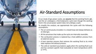
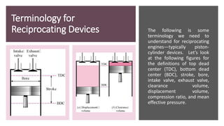
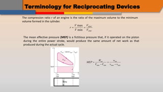
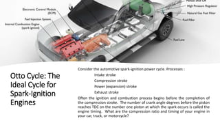
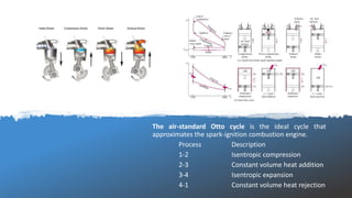
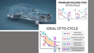
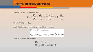
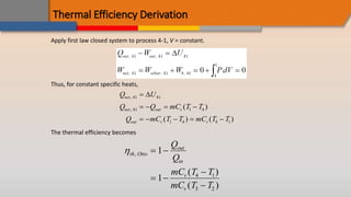
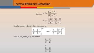
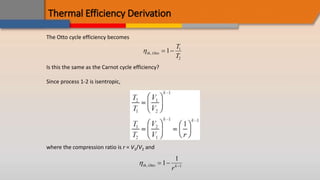
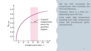
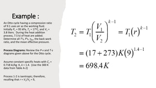
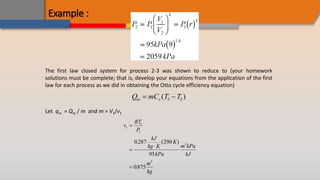
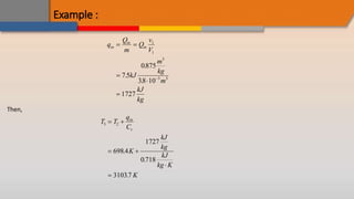
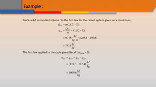
TERMODINAMIKA TEKNIK II
Bahasan: Bab 9 (Bagian 1)
Siklus Pembangkit Daya Gas (Siklus Otto)
Oleh: Noviyanti Nugraha
Muhammad Ridwan
Prodi Teknik Mesin
INSTITUT TEKNOLOGI NASIONAL BANDUNG
novianti@itenas.ac.id – ridwan@itenas.ac.id
Air-Standard Assumptions
In our study of gas power cycles, we assume that the working fluid is air,
and the air undergoes a thermodynamic cycle even though the working
fluid in the actual power system does not undergo a cycle
To simplify the analysis, we approximate the cycles with the following
assumptions:
• The air continuously circulates in a closed loop and always behaves as
an ideal gas.
• All the processes that make up the cycle are internally reversible.
• The combustion process is replaced by a heat-addition process from
an external source.
• A heat rejection process that restores the working fluid to its initial
state replaces the exhaust process.
• The cold-air-standard assumptions apply when the working fluid is air
and has constant specific heat evaluated at room temperature (25oC
or 77oF).
Terminology for
Reciprocating Devices The following is some
terminology we need to
understand for reciprocating
engines—typically piston-
cylinder devices. Let’s look
at the following figures for
the definitions of top dead
center (TDC), bottom dead
center (BDC), stroke, bore,
intake valve, exhaust valve,
clearance volume,
displacement volume,
compression ratio, and mean
effective pressure.
Terminology for Reciprocating Devices
The compression ratio r of an engine is the ratio of the maximum volume to the minimum
volume formed in the cylinder.
r
V
V
V
V
BDC
TDC
 
max
min
The mean effective pressure (MEP) is a fictitious pressure that, if it operated on the piston
during the entire power stroke, would produce the same amount of net work as that
produced during the actual cycle.
MEP
W
V V
w
v v
net net




max min max min
Otto Cycle: The
Ideal Cycle for
Spark-Ignition
Engines
Consider the automotive spark-ignition power cycle. Processes :
Intake stroke
Compression stroke
Power (expansion) stroke
Exhaust stroke
Often the ignition and combustion process begins before the completion of
the compression stroke. The number of crank angle degrees before the piston
reaches TDC on the number one piston at which the spark occurs is called the
engine timing. What are the compression ratio and timing of your engine in
your car, truck, or motorcycle?
The air-standard Otto cycle is the ideal cycle that
approximates the spark-ignition combustion engine.
Process Description
1-2 Isentropic compression
2-3 Constant volume heat addition
3-4 Isentropic expansion
4-1 Constant volume heat rejection
Thermal Efficiency Derivation
Thermal Efficiency of the Otto cycle:
th
net
in
net
in
in out
in
out
in
W
Q
Q
Q
Q Q
Q
Q
Q
  

 
1
Now to find Qin and Qout.
Apply first law closed system to process 2-3, V = constant.
Thus, for constant specific heats,
Q U
Q Q mC T T
net
net in v
,
, ( )
23 23
23 3 2

  

Thermal Efficiency Derivation
Apply first law closed system to process 4-1, V = constant.
Thus, for constant specific heats,
Q U
Q Q mC T T
Q mC T T mC T T
net
net out v
out v v
,
, ( )
( ) ( )
41 41
41 1 4
1 4 4 1

   
    

The thermal efficiency becomes
th Otto
out
in
v
v
Q
Q
mC T T
mC T T
,
( )
( )
 
 


1
1 4 1
3 2
Thermal Efficiency Derivation
th Otto
T T
T T
T T T
T T T
,
( )
( )
( / )
( / )
 


 


1
1
1
1
4 1
3 2
1 4 1
2 3 2
Recall processes 1-2 and 3-4 are isentropic, so
Since V3 = V2 and V4 = V1, we see that
T
T
T
T
or
T
T
T
T
2
1
3
4
4
1
3
2


Thermal Efficiency Derivation
The Otto cycle efficiency becomes
th Otto
T
T
,  
1 1
2
Is this the same as the Carnot cycle efficiency?
Since process 1-2 is isentropic,
where the compression ratio is r = V1/V2 and
th Otto k
r
,   
1
1
1
Example :
An Otto cycle having a compression ratio
of 9:1 uses air as the working fluid.
Initially P1 = 95 kPa, T1 = 17oC, and V1 =
3.8 liters. During the heat addition
process, 7.5 kJ of heat are added.
Determine all T's, P's, th, the back work
ratio, and the mean effective pressure.
Process Diagrams: Review the P-v and T-s
diagrams given above for the Otto cycle.
Assume constant specific heats with Cv =
0.718 kJ/kg K, k = 1.4. (Use the 300 K
data from Table A-2)
Process 1-2 is isentropic; therefore,
recalling that r = V1/V2 = 9,
Example :
The first law closed system for process 2-3 was shown to reduce to (your homework
solutions must be complete; that is, develop your equations from the application of the first
law for each process as we did in obtaining the Otto cycle efficiency equation)
Q mC T T
in v
 
( )
3 2
Let qin = Qin / m and m = V1/v1
v
RT
P
kJ
kg K
K
kPa
m kPa
kJ
m
kg
1
1
1
3
3
0 287 290
95
0875




. ( )
.
Example :
q
Q
m
Q
v
V
kJ
m
kg
m
kJ
kg
in
in
in
 




1
1
3
3 3
7 5
0875
38 10
1727
.
.
.
Then,
T T
q
C
K
kJ
kg
kJ
kg K
K
in
v
3 2
698 4
1727
0 718
31037
 
 


.
.
.
Example :
Process 4-1 is constant volume. So the first law for the closed system gives, on a mass basis,
Q mC T T
q
Q
m
C T T
kJ
kg K
K
kJ
kg
out v
out
out
v
 
  




( )
( )
. ( . )
.
4 1
4 1
0 718 12888 290
7171
The first law applied to the cycle gives (Recall ucycle = 0)
w q q q
kJ
kg
kJ
kg
net net in out
  
 

( . )
.
1727 717 4
1009 6
Example : The thermal efficiency is
th Otto
net
in
w
q
kJ
kg
kJ
kg
or
,
.
. .
 

1009 6
1727
0585 585%
The mean effective pressure is
max min max min
1 2 1 2 1 1
3
3
(1 / ) (1 1/ )
1009.6
1298
1
0.875 (1 )
9
net net
net net net
W w
MEP
V V v v
w w w
v v v v v v r
kJ
m kPa
kg
kPa
m kJ
kg
 
 
  
  
 

The back work ratio is
2 1
12 2 1
exp 34 3 4 3 4
( ) ( )
( ) ( )
0.225 22.5%
comp v
v
w C T T
u T T
BWR
w u C T T T T
or

 
   
  

Terimakasih

Itenas termodinamika ii bab 9a

  • 1.
    TERMODINAMIKA TEKNIK II Bahasan:Bab 9 (Bagian 1) Siklus Pembangkit Daya Gas (Siklus Otto) Oleh: Noviyanti Nugraha Muhammad Ridwan Prodi Teknik Mesin INSTITUT TEKNOLOGI NASIONAL BANDUNG novianti@itenas.ac.id – ridwan@itenas.ac.id
  • 2.
    Air-Standard Assumptions In ourstudy of gas power cycles, we assume that the working fluid is air, and the air undergoes a thermodynamic cycle even though the working fluid in the actual power system does not undergo a cycle To simplify the analysis, we approximate the cycles with the following assumptions: • The air continuously circulates in a closed loop and always behaves as an ideal gas. • All the processes that make up the cycle are internally reversible. • The combustion process is replaced by a heat-addition process from an external source. • A heat rejection process that restores the working fluid to its initial state replaces the exhaust process. • The cold-air-standard assumptions apply when the working fluid is air and has constant specific heat evaluated at room temperature (25oC or 77oF).
  • 3.
    Terminology for Reciprocating DevicesThe following is some terminology we need to understand for reciprocating engines—typically piston- cylinder devices. Let’s look at the following figures for the definitions of top dead center (TDC), bottom dead center (BDC), stroke, bore, intake valve, exhaust valve, clearance volume, displacement volume, compression ratio, and mean effective pressure.
  • 4.
    Terminology for ReciprocatingDevices The compression ratio r of an engine is the ratio of the maximum volume to the minimum volume formed in the cylinder. r V V V V BDC TDC   max min The mean effective pressure (MEP) is a fictitious pressure that, if it operated on the piston during the entire power stroke, would produce the same amount of net work as that produced during the actual cycle. MEP W V V w v v net net     max min max min
  • 5.
    Otto Cycle: The IdealCycle for Spark-Ignition Engines Consider the automotive spark-ignition power cycle. Processes : Intake stroke Compression stroke Power (expansion) stroke Exhaust stroke Often the ignition and combustion process begins before the completion of the compression stroke. The number of crank angle degrees before the piston reaches TDC on the number one piston at which the spark occurs is called the engine timing. What are the compression ratio and timing of your engine in your car, truck, or motorcycle?
  • 6.
    The air-standard Ottocycle is the ideal cycle that approximates the spark-ignition combustion engine. Process Description 1-2 Isentropic compression 2-3 Constant volume heat addition 3-4 Isentropic expansion 4-1 Constant volume heat rejection
  • 8.
    Thermal Efficiency Derivation ThermalEfficiency of the Otto cycle: th net in net in in out in out in W Q Q Q Q Q Q Q Q       1 Now to find Qin and Qout. Apply first law closed system to process 2-3, V = constant. Thus, for constant specific heats, Q U Q Q mC T T net net in v , , ( ) 23 23 23 3 2     
  • 9.
    Thermal Efficiency Derivation Applyfirst law closed system to process 4-1, V = constant. Thus, for constant specific heats, Q U Q Q mC T T Q mC T T mC T T net net out v out v v , , ( ) ( ) ( ) 41 41 41 1 4 1 4 4 1            The thermal efficiency becomes th Otto out in v v Q Q mC T T mC T T , ( ) ( )       1 1 4 1 3 2
  • 10.
    Thermal Efficiency Derivation thOtto T T T T T T T T T T , ( ) ( ) ( / ) ( / )         1 1 1 1 4 1 3 2 1 4 1 2 3 2 Recall processes 1-2 and 3-4 are isentropic, so Since V3 = V2 and V4 = V1, we see that T T T T or T T T T 2 1 3 4 4 1 3 2  
  • 11.
    Thermal Efficiency Derivation TheOtto cycle efficiency becomes th Otto T T ,   1 1 2 Is this the same as the Carnot cycle efficiency? Since process 1-2 is isentropic, where the compression ratio is r = V1/V2 and th Otto k r ,    1 1 1
  • 13.
    Example : An Ottocycle having a compression ratio of 9:1 uses air as the working fluid. Initially P1 = 95 kPa, T1 = 17oC, and V1 = 3.8 liters. During the heat addition process, 7.5 kJ of heat are added. Determine all T's, P's, th, the back work ratio, and the mean effective pressure. Process Diagrams: Review the P-v and T-s diagrams given above for the Otto cycle. Assume constant specific heats with Cv = 0.718 kJ/kg K, k = 1.4. (Use the 300 K data from Table A-2) Process 1-2 is isentropic; therefore, recalling that r = V1/V2 = 9,
  • 14.
    Example : The firstlaw closed system for process 2-3 was shown to reduce to (your homework solutions must be complete; that is, develop your equations from the application of the first law for each process as we did in obtaining the Otto cycle efficiency equation) Q mC T T in v   ( ) 3 2 Let qin = Qin / m and m = V1/v1 v RT P kJ kg K K kPa m kPa kJ m kg 1 1 1 3 3 0 287 290 95 0875     . ( ) .
  • 15.
    Example : q Q m Q v V kJ m kg m kJ kg in in in       1 1 3 33 7 5 0875 38 10 1727 . . . Then, T T q C K kJ kg kJ kg K K in v 3 2 698 4 1727 0 718 31037       . . .
  • 16.
    Example : Process 4-1is constant volume. So the first law for the closed system gives, on a mass basis, Q mC T T q Q m C T T kJ kg K K kJ kg out v out out v          ( ) ( ) . ( . ) . 4 1 4 1 0 718 12888 290 7171 The first law applied to the cycle gives (Recall ucycle = 0) w q q q kJ kg kJ kg net net in out       ( . ) . 1727 717 4 1009 6
  • 17.
    Example : Thethermal efficiency is th Otto net in w q kJ kg kJ kg or , . . .    1009 6 1727 0585 585% The mean effective pressure is max min max min 1 2 1 2 1 1 3 3 (1 / ) (1 1/ ) 1009.6 1298 1 0.875 (1 ) 9 net net net net net W w MEP V V v v w w w v v v v v v r kJ m kPa kg kPa m kJ kg              The back work ratio is 2 1 12 2 1 exp 34 3 4 3 4 ( ) ( ) ( ) ( ) 0.225 22.5% comp v v w C T T u T T BWR w u C T T T T or           
  • 18.