Download as PDF, PPTX

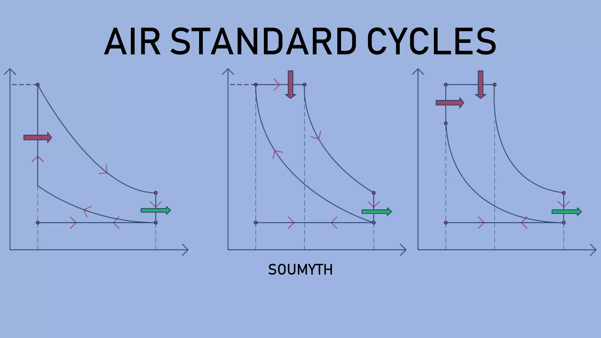

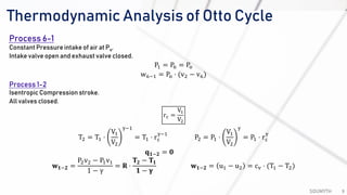
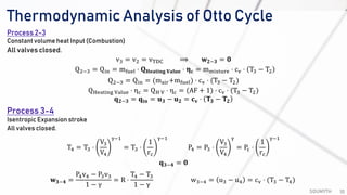
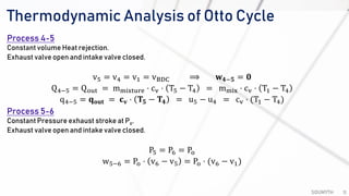
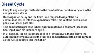
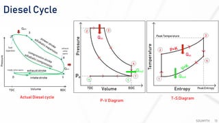
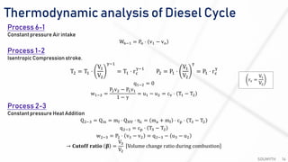
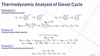
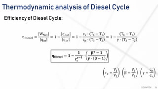
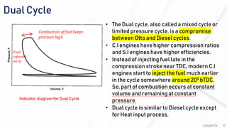
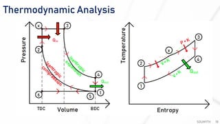

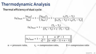
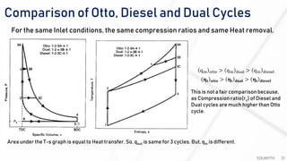
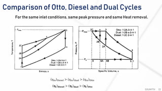
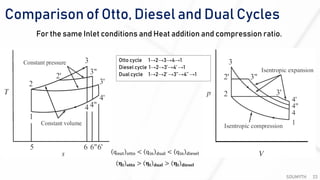

The document discusses various air standard cycles that are used to model internal combustion engine processes, including the Otto, Diesel, and dual cycles. It provides details on the assumptions and thermodynamic processes that define each cycle. The Otto cycle consists of four processes: constant-pressure intake, isentropic compression, constant-volume combustion, and isentropic expansion. The Diesel cycle models combustion as a constant-pressure process rather than constant volume. The dual cycle models combustion as both constant-volume and constant-pressure processes. Comparisons are made between the cycles in terms of their heat transfer and thermal efficiencies.