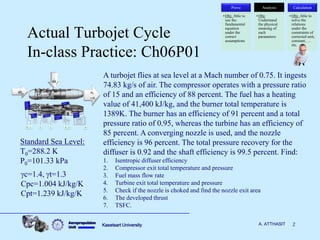
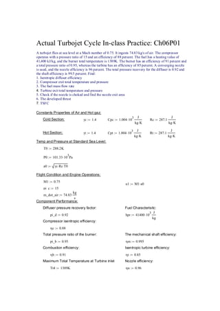
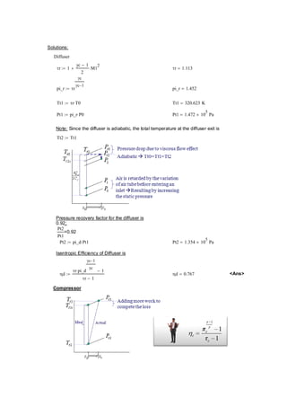
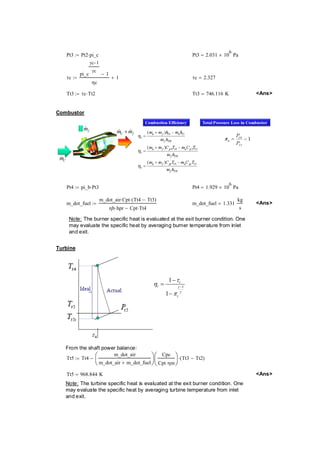
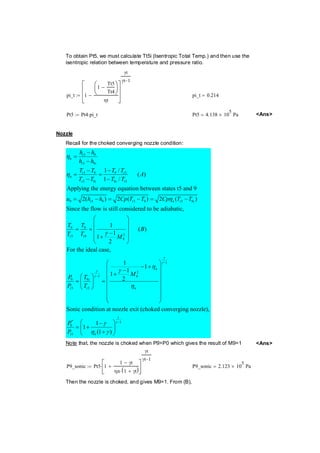
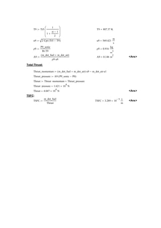
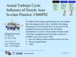
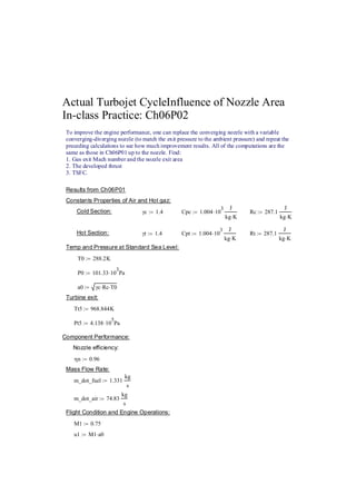
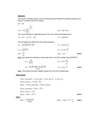
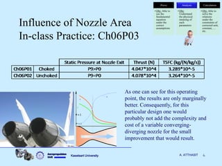
Aeropropulsion 
Unit 
Non-Ideal Cycle Analysis 
2005 - 2010 
International School of Engineering, Chulalongkorn University 
Regular Program and International Double Degree Program, Kasetsart University 
Assist. Prof. Anurak Atthasit, Ph.D.
Aeropropulsion 
Unit Kasetsart University A. ATTHASIT 2 
Actual Turbojet Cycle 
In-class Practice: Ch06P01 
0 1 2 3 4 5 9 
0 m 
f m 
0 
f 
m 
m 
A turbojet flies at sea level at a Mach number of 0.75. It ingests 
74.83 kg/s of air. The compressor operates with a pressure ratio 
of 15 and an efficiency of 88 percent. The fuel has a heating 
value of 41,400 kJ/kg, and the burner total temperature is 
1389K. The burner has an efficiency of 91 percent and a total 
pressure ratio of 0.95, whereas the turbine has an efficiency of 
85 percent. A converging nozzle is used, and the nozzle 
efficiency is 96 percent. The total pressure recovery for the 
diffuser is 0.92 and the shaft efficiency is 99.5 percent. Find: 
1. Isentropic diffuser efficiency 
2. Compressor exit total temperature and pressure 
3. Fuel mass flow rate 
4. Turbine exit total temperature and pressure 
5. Check if the nozzle is choked and find the nozzle exit area 
6. The developed thrust 
7. TSFC. 
Prove 
• Obj: Able to 
use the 
fundamental 
equation 
under the 
correct 
assumptions 
Analysis 
• Obj: 
Understand 
the physical 
meaning of 
each 
parameters 
Calculation 
• Obj: Able to 
solve the 
relations 
under the 
constraints of 
corrected unit, 
constant, … 
etc. 
Standard Sea Level: 
T0=288.2 K 
P0=101.33 kPa 
gc=1.4, gt=1.3 
Cpc=1.004 kJ/kg/K 
Cpt=1.239 kJ/kg/K
Actual Turbojet Cycle In-class Practice: Ch06P01 
A turbojet flies at sea level at a Mach number of 0.75. It ingests 74.83 kg/s of air. The compressor 
operates with a pressure ratio of 15 and an efficiency of 88 percent. The fuel has a heating value of 
41,400 kJ/kg, and the burner total temperature is 1389K. The burner has an efficiency of 91 percent and 
a total pressure ratio of 0.95, whereas the turbine has an efficiency of 85 percent. A converging nozzle 
is used, and the nozzle efficiency is 96 percent. The total pressure recovery for the diffuser is 0.92 and 
the shaft efficiency is 99.5 percent. Find: 
1. Isentropic diffuser efficiency 
2. Compressor exit total temperature and pressure 
3. The fuel mass flow rate 
4. Turbine exit total temperature and pressure 
5. Check if the nozzle is choked and find the nozzle exit area 
6. The developed thrust 
7. TSFC 
Constants Properties of Air and Hot gaz: 
Cold Section: γc := 1.4 Cpc 1.004⋅103 J 
kg K ⋅ 
:= Rc 287.1 
J 
kg K ⋅ 
:= 
Hot Section: γt 1.4 := Cpt 1.00410⋅ 3 J 
kg K ⋅ 
:= Rt 287.1 
J 
kg K ⋅ 
:= 
Temp and Pressure at Standard Sea Level: 
T0 288.2K := 
P0 101.3310:= ⋅ 3Pa 
a0 γc Rc := ⋅ ⋅T0 
Flight Condition and Engine Operations: 
M1 0.75 := 
u1 M1a0 := ⋅ 
pi_c 15 := 
m_dot_air 74.83 
kg 
s 
:= 
Component Performance: 
Diffuser pressure recovery factor:Fuel Characterisitc: 
pi_d 0.92 := hpr 4140010⋅ 3 J 
kg 
:= 
Compressor isentropic efficiency: 
ηc 0.88 := 
Total pressure ratio of the burner:The mechanical shaft efficiency: 
pi_b 0.95 := ηm 0.995 := 
Combustion efficiency:Isentropic turbine efficiency: 
ηb 0.91 := ηt 0.85 := 
Maximum Total Temperature at Turbine inletNozzle efficiency: 
Tt4 1389K := ηn 0.96 :=
Solutions: 
Diffuser 
τr 1 
γc − 1 
2 
:= + ⋅M12 τr 1.113 = 
pi_r τr 
γc 
γc−1 
:= pi_r 1.452 = 
Tt1 τr T0 := ⋅ Tt1 320.623K = 
Pt1 pi_rP0 := ⋅ Pt1 1.47210= × 5 Pa 
Note: Since the diffuser is adiabatic, the total temperature at the diffuser exit is 
Tt2 Tt1 := 
Pressure recovery factor for the diffuser is 
0.92; 
Pt2 
Pt1 
=0.92 
Pt2 pi_dPt1 := ⋅ Pt2 1.35410= × 5 Pa 
Isentropic Efficiency of Diffuser is 
ηd 
τr pi_d 
γc−1 
⋅ γc − 1 
τr − 1 
:= ηd 0.767 = <Ans> 
Compressor
Pt3 := Pt2⋅pi_c Pt3 2.03110= × 6 Pa 
τc 
pi_c 
γc−1 
γc − 1 
ηc 
:= + 1 τc 2.327 = 
Tt3 τc Tt2 := ⋅ Tt3 746.116K = <Ans> 
Combustor 
C m 
f m 
C f m +m 
Pt4 pi_bPt3 := ⋅ Pt4 1.92910= × 6 Pa 
m_dot_fuel 
m_dot_air Cpt ⋅ Tt4 Tt3 ⋅( − ) 
ηb hpr ⋅ Cpt Tt4 − ⋅ 
:= m_dot_fuel 1.331 
kg 
s 
= Ans 
Note: The burner specific heat is evaluated at the exit burner condition. One 
may evaluate the specific heat by averaging burner temperature from inlet 
and exit. 
Turbine 
1 
1 
1 
t 
t 
t 
γ 
γ 
τ 
η 
π 
− 
− 
= 
− 
From the shaft power balance: 
Tt5 Tt4 
m_dot_air 
m_dot_air m_dot_fuel + 
⎛⎜⎝⎞⎟⎠ 
Cpc 
Cpt⋅ηm 
⎛⎜⎝ 
⎞⎟⎠ 
Tt3 Tt2 := − ⋅( − ) 
Tt5 968.844K = Ans 
Note: The turbine specific heat is evaluated at the exit burner condition. One 
may evaluate the specific heat by averaging turbine temperature from inlet 
and exit.
To obtain Pt5, we must calculate Tt5i (Isentropic Total Temp.) and then use the 
isentropic relation between temperature and pressure ratio. 
pi_t 1 
1 
Tt5 
Tt4 
− ⎛⎜⎝ 
⎞⎟⎠ 
ηt 
− 
⎡⎢⎢⎣ 
⎤⎥⎥⎦ 
γt 
γt−1 
:= pi_t 0.214 = 
Pt5 Pt4pi_t := ⋅ Pt5 4.13810= × 5 Pa Ans 
Nozzle 
Recall for the choked converging nozzle condition: 
5 9 
5 9 
5 9 95 
5 9 95 
9 5 95959 
9 
5 
1 / ( ) 
1 / 
Applying the energy equation between states t5 and 9 
2( )2()2() 
Since the flow is still considered to be adiabatic, 
t 
n 
t i 
t t 
n 
t i it 
t t nti 
t 
h h 
h h 
T T TT A 
T T TT 
u h hCpTTCpTT 
T 
T 
η 
η 
η 
− 
= 
− 
− − 
= = 
− − 
= − =−=− 
9 
9 2 
9 
1 
2 
1 9 
9 9 
5 5 
* 1 
9 
5 
1 ( ) 1 1 
2 
For the ideal case, 
1 1 1 1 
2 
Sonic condition at nozzle exit (choked converging nozzle), 
1 1 
(1 ) 
t 
n 
i 
t t n 
t n 
T B 
T M 
P T M 
P T 
P 
P 
γ 
γ 
γ 
γ 
γ 
γ 
γ 
η 
γ 
η 
γ 
η γ 
− 
− 
− 
⎛ ⎞ 
⎜ ⎟ 
= = ⎜ ⎟ ⎜ − ⎟ + 
⎝ ⎠ 
⎛ − + ⎞ ⎜ − ⎟ 
⎛ ⎞ ⎜ + ⎟ 
= ⎜ ⎟ = ⎜ ⎟ 
⎝ ⎠ ⎜ ⎟ 
⎜ ⎟ 
⎜ ⎟ 
⎝ ⎠ 
⎛ − ⎞ 
= ⎜ + ⎟ ⎝ + ⎠ 
Note that, the nozzle is choked when P9P0 which gives the result of M9=1 Ans 
P9_sonic Pt51 
1 − γt 
ηn⋅(1 + γt) 
+ ⎡⎢⎣ 
⎤⎥⎦ 
γt 
γt−1 
:= ⋅ P9_sonic 2.12310= × 5 Pa 
Then the nozzle is choked, and gives M9=1. From (B),
T9 Tt5 
1 
1 
γt − 1 
2 
+ 
⎛⎜⎜⎝ 
⎞⎟⎟⎠ 
:= ⋅ T9 807.37K = 
u9 2Cpt ⋅ Tt5 T9 := ⋅( − ) u9 569.421 
m 
s 
= 
ρ9 
P9_sonic 
Rt T9 ⋅ 
:= ρ9 0.916 
kg 
m3 
= 
A9 
m_dot_fuel m_dot_air ( + ) 
ρ9 u9 ⋅ 
:= A9 0.146m= 2 Ans 
Total Thrust: 
Thrust_momentum m_dot_fuelm_dot_air ( + ) u9 ⋅ m_dot_air u1 := − ⋅ 
Thrust_pressure A9P9_sonicP0 := ⋅( − ) 
Thrust Thrust_momentumThrust_pressure := + 
Thrust_pressure 1.62110= × 4 N 
Thrust 4.04710= × 4 N Ans 
TSFC: 
TSFC 
m_dot_fuel 
Thrust 
:= TSFC 3.28910 − 5 × s 
m 
= Ans
Aeropropulsion 
Unit Kasetsart University A. ATTHASIT 3 
Actual Turbojet Cycle 
Influence of Nozzle Area 
In-class Practice: Ch06P02 
Prove 
• Obj: Able to 
use the 
fundamental 
equation 
under the 
correct 
assumptions 
Analysis 
• Obj: 
Understand 
the physical 
meaning of 
each 
parameters 
Calculation 
• Obj: Able to 
solve the 
relations 
under the 
constraints of 
corrected unit, 
constant, … 
etc. 
0 1 2 3 4 5 9 
0 m 
f m 
0 
f 
m 
m 
To improve the engine performance, one can replace 
the converging nozzle with a variable converging-diverging 
nozzle (to match the exit pressure to the 
ambient pressure) and repeat the preceding 
calculations to see how much improvement results. 
All of the computations are the same as those in 
Ch06P01 up to the nozzle. Find: 
1. Gas exit Mach number and the nozzle exit area 
2. The developed thrust 
3. TSFC. 
Standard Sea Level: 
T0=288.2 K 
P0=101.33 kPa 
gc=1.4, gt=1.3 
Cpc=1.004 kJ/kg/K 
Cpt=1.239 kJ/kg/K
Actual Turbojet CycleInfluence of Nozzle Area 
In-class Practice: Ch06P02 
To improve the engine performance, one can replace the converging nozzle with a variable 
converging-diverging nozzle (to match the exit pressure to the ambient pressure) and repeat the 
preceding calculations to see how much improvement results. All of the computations are the 
same as those in Ch06P01 up to the nozzle. Find: 
1. Gas exit Mach number and the nozzle exit area 
2. The developed thrust 3. TSFC. 
Results from Ch06P01 
Constants Properties of Air and Hot gaz: 
Cold Section: γc := 1.4 Cpc 1.004⋅103 J 
kg K ⋅ 
:= Rc 287.1 
J 
kg K ⋅ 
:= 
Hot Section: γt 1.4 := Cpt 1.00410⋅ 3 J 
kg K ⋅ 
:= Rt 287.1 
J 
kg K ⋅ 
:= 
Temp and Pressure at Standard Sea Level: 
T0 288.2K := 
P0 101.3310:= ⋅ 3Pa 
a0 γc Rc := ⋅ ⋅T0 
Turbine exit: 
Tt5 968.844K := 
Pt5 4.13810:= ⋅ 5Pa 
Component Performance: 
Nozzle efficiency: 
ηn 0.96 := 
Mass Flow Rate: 
m_dot_fuel 1.331 
kg 
s 
:= 
m_dot_air 74.83 
kg 
s 
:= 
Flight Condition and Engine Operations: 
M1 0.75 := 
u1 M1a0 := ⋅
Solutions 
The nozzle is variable nozzle, and so the exit pressure matches the ambient pressure and 
there is no need to check for choking 
P9 P0 := 
T9i Tt5 
P9 
Pt5 
⎛⎜⎝ 
⎞⎟⎠ 
γt−1 
γt 
:= ⋅ T9i 648.138K = 
The nozzle efficiency is again 96 percent, thus, the nozzle exit temperature is 
T9 Tt5 ηn Tt5T9i := − ⋅( − ) T9 660.966K = 
The exit speed can obtain from the energy equation, 
u9 2Cpt ⋅ Tt5 T9 := ⋅( − ) u9 786.269 
m 
s 
= 
a9 γt Rt := ⋅ ⋅T9 a9 515.431 
m 
s 
= 
M9 
u9 
a9 
:= M9 1.525 = Ans 
Note: the hot gas exit velocity is much higher than one of the choked case (Ch06P01). 
ρ9 
P9 
Rt T9 ⋅ 
:= ρ9 0.534 
kg 
m3 
= 
A9 
m_dot_fuel m_dot_air ( + ) 
ρ9 u9 ⋅ 
:= A9 0.181m= 2 Ans 
Note: The Nozzle exit area is slightly higher than one of the choked case. 
Total Thrust: 
Thrust_momentum m_dot_fuelm_dot_air ( + ) u9 ⋅ m_dot_air u1 := − ⋅ 
Thrust_pressure A9P9P0 := ⋅( − ) 
Thrust Thrust_momentumThrust_pressure := + 
Thrust_momentum 4.07810= × 4 N 
Thrust_pressure 0N = 
Thrust 4.07810= × 4 N Ans 
TSFC: 
TSFC 
m_dot_fuel 
Thrust 
:= TSFC 3.26410 − 5 × s 
m 
= Ans
Aeropropulsion 
Unit 
Kasetsart University 
4 
A. ATTHASIT 
Influence of Nozzle Area In-class Practice: Ch06P03 
Prove 
•Obj: Able to use the fundamental equation under the correct assumptions 
Analysis 
•Obj: Understand the physical meaning of each parameters 
Calculation 
•Obj: Able to solve the relations under the constraints of corrected unit, constant, … etc. 
As one can see for this operating point, the results are only marginally better. Consequently, for this particular design one would probably not add the complexity and cost of a variable converging- diverging nozzle for the small improvement that would result.
Aeropropulsion 
Unit Kasetsart University A. ATTHASIT 5 
Conclusion 
* 
2 
1 
* 
2 
1 
1 
* 
* 
2 
* 
1 
2( 1) 
2 
* 
1 
2 
1 
1 
2 
1 
2 
1 
1 
2 
1 
2 
1 
1 
2 
1 
1 
1 2 
1 
2 
T 
T 
M 
P 
P 
M 
P 
P 
T 
M 
T 
P 
m AV AM 
R T 
M 
A 
A M 
g 
g 
g 
g 
g 
g 
g 
g 
g 
g 
 
 g 
g 
 
g 
g 
 
 
 
 
 
 
   
  
  
   
  
   
            
   
  
    
            
  
     
     
     
   
  
  
2 
0 
0 t 
dA d du 
A u 
udu dP 
dh dh udu 
dP d dT 
P T 
a 
P 
 
 
 
 
 
 
g 
   
  
   
  
 
P dP 
T dT 
d 
A dA 
u du 
  
 
 
 
 
 
P 
T 
A 
u 
 
dx 
2 
dP 
P  
See You 
Next Class!

Aircraft propulsion non ideal cycle analysis

  • 1.
    Aeropropulsion Unit Non-IdealCycle Analysis 2005 - 2010 International School of Engineering, Chulalongkorn University Regular Program and International Double Degree Program, Kasetsart University Assist. Prof. Anurak Atthasit, Ph.D.
  • 2.
    Aeropropulsion Unit KasetsartUniversity A. ATTHASIT 2 Actual Turbojet Cycle In-class Practice: Ch06P01 0 1 2 3 4 5 9 0 m f m 0 f m m A turbojet flies at sea level at a Mach number of 0.75. It ingests 74.83 kg/s of air. The compressor operates with a pressure ratio of 15 and an efficiency of 88 percent. The fuel has a heating value of 41,400 kJ/kg, and the burner total temperature is 1389K. The burner has an efficiency of 91 percent and a total pressure ratio of 0.95, whereas the turbine has an efficiency of 85 percent. A converging nozzle is used, and the nozzle efficiency is 96 percent. The total pressure recovery for the diffuser is 0.92 and the shaft efficiency is 99.5 percent. Find: 1. Isentropic diffuser efficiency 2. Compressor exit total temperature and pressure 3. Fuel mass flow rate 4. Turbine exit total temperature and pressure 5. Check if the nozzle is choked and find the nozzle exit area 6. The developed thrust 7. TSFC. Prove • Obj: Able to use the fundamental equation under the correct assumptions Analysis • Obj: Understand the physical meaning of each parameters Calculation • Obj: Able to solve the relations under the constraints of corrected unit, constant, … etc. Standard Sea Level: T0=288.2 K P0=101.33 kPa gc=1.4, gt=1.3 Cpc=1.004 kJ/kg/K Cpt=1.239 kJ/kg/K
  • 3.
    Actual Turbojet CycleIn-class Practice: Ch06P01 A turbojet flies at sea level at a Mach number of 0.75. It ingests 74.83 kg/s of air. The compressor operates with a pressure ratio of 15 and an efficiency of 88 percent. The fuel has a heating value of 41,400 kJ/kg, and the burner total temperature is 1389K. The burner has an efficiency of 91 percent and a total pressure ratio of 0.95, whereas the turbine has an efficiency of 85 percent. A converging nozzle is used, and the nozzle efficiency is 96 percent. The total pressure recovery for the diffuser is 0.92 and the shaft efficiency is 99.5 percent. Find: 1. Isentropic diffuser efficiency 2. Compressor exit total temperature and pressure 3. The fuel mass flow rate 4. Turbine exit total temperature and pressure 5. Check if the nozzle is choked and find the nozzle exit area 6. The developed thrust 7. TSFC Constants Properties of Air and Hot gaz: Cold Section: γc := 1.4 Cpc 1.004⋅103 J kg K ⋅ := Rc 287.1 J kg K ⋅ := Hot Section: γt 1.4 := Cpt 1.00410⋅ 3 J kg K ⋅ := Rt 287.1 J kg K ⋅ := Temp and Pressure at Standard Sea Level: T0 288.2K := P0 101.3310:= ⋅ 3Pa a0 γc Rc := ⋅ ⋅T0 Flight Condition and Engine Operations: M1 0.75 := u1 M1a0 := ⋅ pi_c 15 := m_dot_air 74.83 kg s := Component Performance: Diffuser pressure recovery factor:Fuel Characterisitc: pi_d 0.92 := hpr 4140010⋅ 3 J kg := Compressor isentropic efficiency: ηc 0.88 := Total pressure ratio of the burner:The mechanical shaft efficiency: pi_b 0.95 := ηm 0.995 := Combustion efficiency:Isentropic turbine efficiency: ηb 0.91 := ηt 0.85 := Maximum Total Temperature at Turbine inletNozzle efficiency: Tt4 1389K := ηn 0.96 :=
  • 4.
    Solutions: Diffuser τr1 γc − 1 2 := + ⋅M12 τr 1.113 = pi_r τr γc γc−1 := pi_r 1.452 = Tt1 τr T0 := ⋅ Tt1 320.623K = Pt1 pi_rP0 := ⋅ Pt1 1.47210= × 5 Pa Note: Since the diffuser is adiabatic, the total temperature at the diffuser exit is Tt2 Tt1 := Pressure recovery factor for the diffuser is 0.92; Pt2 Pt1 =0.92 Pt2 pi_dPt1 := ⋅ Pt2 1.35410= × 5 Pa Isentropic Efficiency of Diffuser is ηd τr pi_d γc−1 ⋅ γc − 1 τr − 1 := ηd 0.767 = <Ans> Compressor
  • 5.
    Pt3 := Pt2⋅pi_cPt3 2.03110= × 6 Pa τc pi_c γc−1 γc − 1 ηc := + 1 τc 2.327 = Tt3 τc Tt2 := ⋅ Tt3 746.116K = <Ans> Combustor C m f m C f m +m Pt4 pi_bPt3 := ⋅ Pt4 1.92910= × 6 Pa m_dot_fuel m_dot_air Cpt ⋅ Tt4 Tt3 ⋅( − ) ηb hpr ⋅ Cpt Tt4 − ⋅ := m_dot_fuel 1.331 kg s = Ans Note: The burner specific heat is evaluated at the exit burner condition. One may evaluate the specific heat by averaging burner temperature from inlet and exit. Turbine 1 1 1 t t t γ γ τ η π − − = − From the shaft power balance: Tt5 Tt4 m_dot_air m_dot_air m_dot_fuel + ⎛⎜⎝⎞⎟⎠ Cpc Cpt⋅ηm ⎛⎜⎝ ⎞⎟⎠ Tt3 Tt2 := − ⋅( − ) Tt5 968.844K = Ans Note: The turbine specific heat is evaluated at the exit burner condition. One may evaluate the specific heat by averaging turbine temperature from inlet and exit.
  • 6.
    To obtain Pt5,we must calculate Tt5i (Isentropic Total Temp.) and then use the isentropic relation between temperature and pressure ratio. pi_t 1 1 Tt5 Tt4 − ⎛⎜⎝ ⎞⎟⎠ ηt − ⎡⎢⎢⎣ ⎤⎥⎥⎦ γt γt−1 := pi_t 0.214 = Pt5 Pt4pi_t := ⋅ Pt5 4.13810= × 5 Pa Ans Nozzle Recall for the choked converging nozzle condition: 5 9 5 9 5 9 95 5 9 95 9 5 95959 9 5 1 / ( ) 1 / Applying the energy equation between states t5 and 9 2( )2()2() Since the flow is still considered to be adiabatic, t n t i t t n t i it t t nti t h h h h T T TT A T T TT u h hCpTTCpTT T T η η η − = − − − = = − − = − =−=− 9 9 2 9 1 2 1 9 9 9 5 5 * 1 9 5 1 ( ) 1 1 2 For the ideal case, 1 1 1 1 2 Sonic condition at nozzle exit (choked converging nozzle), 1 1 (1 ) t n i t t n t n T B T M P T M P T P P γ γ γ γ γ γ γ η γ η γ η γ − − − ⎛ ⎞ ⎜ ⎟ = = ⎜ ⎟ ⎜ − ⎟ + ⎝ ⎠ ⎛ − + ⎞ ⎜ − ⎟ ⎛ ⎞ ⎜ + ⎟ = ⎜ ⎟ = ⎜ ⎟ ⎝ ⎠ ⎜ ⎟ ⎜ ⎟ ⎜ ⎟ ⎝ ⎠ ⎛ − ⎞ = ⎜ + ⎟ ⎝ + ⎠ Note that, the nozzle is choked when P9P0 which gives the result of M9=1 Ans P9_sonic Pt51 1 − γt ηn⋅(1 + γt) + ⎡⎢⎣ ⎤⎥⎦ γt γt−1 := ⋅ P9_sonic 2.12310= × 5 Pa Then the nozzle is choked, and gives M9=1. From (B),
  • 7.
    T9 Tt5 1 1 γt − 1 2 + ⎛⎜⎜⎝ ⎞⎟⎟⎠ := ⋅ T9 807.37K = u9 2Cpt ⋅ Tt5 T9 := ⋅( − ) u9 569.421 m s = ρ9 P9_sonic Rt T9 ⋅ := ρ9 0.916 kg m3 = A9 m_dot_fuel m_dot_air ( + ) ρ9 u9 ⋅ := A9 0.146m= 2 Ans Total Thrust: Thrust_momentum m_dot_fuelm_dot_air ( + ) u9 ⋅ m_dot_air u1 := − ⋅ Thrust_pressure A9P9_sonicP0 := ⋅( − ) Thrust Thrust_momentumThrust_pressure := + Thrust_pressure 1.62110= × 4 N Thrust 4.04710= × 4 N Ans TSFC: TSFC m_dot_fuel Thrust := TSFC 3.28910 − 5 × s m = Ans
  • 8.
    Aeropropulsion Unit KasetsartUniversity A. ATTHASIT 3 Actual Turbojet Cycle Influence of Nozzle Area In-class Practice: Ch06P02 Prove • Obj: Able to use the fundamental equation under the correct assumptions Analysis • Obj: Understand the physical meaning of each parameters Calculation • Obj: Able to solve the relations under the constraints of corrected unit, constant, … etc. 0 1 2 3 4 5 9 0 m f m 0 f m m To improve the engine performance, one can replace the converging nozzle with a variable converging-diverging nozzle (to match the exit pressure to the ambient pressure) and repeat the preceding calculations to see how much improvement results. All of the computations are the same as those in Ch06P01 up to the nozzle. Find: 1. Gas exit Mach number and the nozzle exit area 2. The developed thrust 3. TSFC. Standard Sea Level: T0=288.2 K P0=101.33 kPa gc=1.4, gt=1.3 Cpc=1.004 kJ/kg/K Cpt=1.239 kJ/kg/K
  • 9.
    Actual Turbojet CycleInfluenceof Nozzle Area In-class Practice: Ch06P02 To improve the engine performance, one can replace the converging nozzle with a variable converging-diverging nozzle (to match the exit pressure to the ambient pressure) and repeat the preceding calculations to see how much improvement results. All of the computations are the same as those in Ch06P01 up to the nozzle. Find: 1. Gas exit Mach number and the nozzle exit area 2. The developed thrust 3. TSFC. Results from Ch06P01 Constants Properties of Air and Hot gaz: Cold Section: γc := 1.4 Cpc 1.004⋅103 J kg K ⋅ := Rc 287.1 J kg K ⋅ := Hot Section: γt 1.4 := Cpt 1.00410⋅ 3 J kg K ⋅ := Rt 287.1 J kg K ⋅ := Temp and Pressure at Standard Sea Level: T0 288.2K := P0 101.3310:= ⋅ 3Pa a0 γc Rc := ⋅ ⋅T0 Turbine exit: Tt5 968.844K := Pt5 4.13810:= ⋅ 5Pa Component Performance: Nozzle efficiency: ηn 0.96 := Mass Flow Rate: m_dot_fuel 1.331 kg s := m_dot_air 74.83 kg s := Flight Condition and Engine Operations: M1 0.75 := u1 M1a0 := ⋅
  • 10.
    Solutions The nozzleis variable nozzle, and so the exit pressure matches the ambient pressure and there is no need to check for choking P9 P0 := T9i Tt5 P9 Pt5 ⎛⎜⎝ ⎞⎟⎠ γt−1 γt := ⋅ T9i 648.138K = The nozzle efficiency is again 96 percent, thus, the nozzle exit temperature is T9 Tt5 ηn Tt5T9i := − ⋅( − ) T9 660.966K = The exit speed can obtain from the energy equation, u9 2Cpt ⋅ Tt5 T9 := ⋅( − ) u9 786.269 m s = a9 γt Rt := ⋅ ⋅T9 a9 515.431 m s = M9 u9 a9 := M9 1.525 = Ans Note: the hot gas exit velocity is much higher than one of the choked case (Ch06P01). ρ9 P9 Rt T9 ⋅ := ρ9 0.534 kg m3 = A9 m_dot_fuel m_dot_air ( + ) ρ9 u9 ⋅ := A9 0.181m= 2 Ans Note: The Nozzle exit area is slightly higher than one of the choked case. Total Thrust: Thrust_momentum m_dot_fuelm_dot_air ( + ) u9 ⋅ m_dot_air u1 := − ⋅ Thrust_pressure A9P9P0 := ⋅( − ) Thrust Thrust_momentumThrust_pressure := + Thrust_momentum 4.07810= × 4 N Thrust_pressure 0N = Thrust 4.07810= × 4 N Ans TSFC: TSFC m_dot_fuel Thrust := TSFC 3.26410 − 5 × s m = Ans
  • 11.
    Aeropropulsion Unit KasetsartUniversity 4 A. ATTHASIT Influence of Nozzle Area In-class Practice: Ch06P03 Prove •Obj: Able to use the fundamental equation under the correct assumptions Analysis •Obj: Understand the physical meaning of each parameters Calculation •Obj: Able to solve the relations under the constraints of corrected unit, constant, … etc. As one can see for this operating point, the results are only marginally better. Consequently, for this particular design one would probably not add the complexity and cost of a variable converging- diverging nozzle for the small improvement that would result.
  • 12.
    Aeropropulsion Unit KasetsartUniversity A. ATTHASIT 5 Conclusion * 2 1 * 2 1 1 * * 2 * 1 2( 1) 2 * 1 2 1 1 2 1 2 1 1 2 1 2 1 1 2 1 1 1 2 1 2 T T M P P M P P T M T P m AV AM R T M A A M g g g g g g g g g g   g g  g g                                                                               2 0 0 t dA d du A u udu dP dh dh udu dP d dT P T a P       g            P dP T dT d A dA u du        P T A u  dx 2 dP P  See You Next Class!