
Recommended
More Related Content
Similar to Thermodynamic Cycles - A Review - Carnot Cycle, Ideal Gas Law, Thermodynamics Processes, Properties of Air, Diesel Cycle, Dual Cycle, Performance, Power, Efficiency
Similar to Thermodynamic Cycles - A Review - Carnot Cycle, Ideal Gas Law, Thermodynamics Processes, Properties of Air, Diesel Cycle, Dual Cycle, Performance, Power, Efficiency (20)
Recently uploaded
Recently uploaded (20)
Thermodynamic Cycles - A Review - Carnot Cycle, Ideal Gas Law, Thermodynamics Processes, Properties of Air, Diesel Cycle, Dual Cycle, Performance, Power, Efficiency
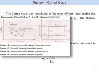
- 1. th net in W Q th Carnot L H T T , 1 Upon derivation the performance of the real cycle is often measured in terms of its thermal efficiency The Carnot cycle was introduced as the most efficient heat engine that operate between two fixed temperatures TH and TL. The thermal efficiency of Carnot cycle is given by Review – Carnot Cycle 1
- 2. The ideal gas equation is defined as mRT PV or RT Pv where P = pressure in kPa v = specific volume in m3/kg (or V = volume in m3) R = ideal gas constant in kJ/kg.K m = mass in kg T = temperature in K Review – Ideal Gas Law 2 The Δu and Δh of ideal gases can be expressed as ) ( 1 2 1 2 T T C u u u v ) ( 1 2 1 2 T T C h h h P Δu - constant volume process Δh - constant pressure process
- 3. Process Description Result of Ideal Gas Law isochoric constant volume (V1 = V2) isobaric constant pressure (P1 = P2) isothermal constant temperature (T1 = T2) polytropic -none- isentropic constant entropy (S1 = S2) According to a law of constant n V P 2 2 1 1 T P T P 2 2 1 1 T V T V 2 2 1 1 V P V P 1 2 1 1 2 2 1 n n n T T V V P P Review – Thermodynamics Processes 3 A polytropic process is a thermodynamic process that obeys the relation pVn=C: where p is the pressure, V is volume, n is the polytropic index, and C is a constant. The polytropic process equation describes expansion and compression processes which include heat transfer. In thermodynamics, an isentropic process is an idealized thermodynamic process that is both adiabatic and reversible. The work transfers of the system are frictionless, and there is no net transfer of heat or matter. In thermodynamics, an adiabatic process is a type of thermodynamic process that occurs without transferring heat or mass between the thermodynamic system and its environment. Unlike an isothermal process, an adiabatic process transfers energy to the surroundings only as work.
- 4. Ideal gas constant, R= 0.2871 kJ/kg.K specific heat at constant pressure, Cp = 1.005 kJ/kg.K specific heat at constant volume, Cv = 0.718 kJ/kg.K specific heat ratio, k = 1.4 Review – Properties of Air 4
- 5. Air continuously circulates in a closed loop. Always behaves as an ideal gas. All the processes that make up the cycle are internally reversible. The combustion process is replaced by a heat-addition process from an external source. Air-Standard Assumptions 6
- 6. A heat rejection process that restores the working fluid to its initial state replaces the exhaust process. The cold-air-standard assumptions apply when the working fluid is air and has constant specific heat evaluated at room temperature (25o C or 77o F). No chemical reaction takes place in the engine. Air-Standard Assumptions 7
- 7. Top dead center (TDC), bottom dead center (BDC), stroke, bore, intake valve, exhaust valve, clearance volume, displacement volume, compression ratio, and mean effective pressure Terminology for Reciprocating Devices 8
- 8. The compression ratio r of an engine is defined as r V V V V BDC TDC max min The mean effective pressure (MEP) is a fictitious pressure that, if it operated on the piston during the entire power stroke, would produce the same amount of net work as that produced during the actual cycle. MEP W V V w v v net net max min max min9
- 9. Otto Cycle The Ideal Cycle for Spark-Ignition Engines 10
- 10. The processes in the Otto cycle are as per following: Process Description 1-2 Isentropic compression 2-3 Constant volume heat addition 3-4 Isentropic expansion 4-1 Constant volume heat rejection 1 2 3 4 Qout Qin Pvg Constant v1 v2 v P s T Qout Qin 1 2 3 4 (a) P-v diagram (b) T-s diagram 11
- 11. Related formula based on basic thermodynamics: Process Description Related formula 1-2 Isentropic compression 2-3 Constant volume heat addition 3-4 Isentropic expansion 4-1 Constant volume heat rejection 1 2 1 1 2 2 1 n n n T T V V P P 1 2 1 1 2 2 1 n n n T T V V P P 3 2 in v Q mC T T 4 1 out v Q mC T T 12
- 12. Thermal efficiency of the Otto cycle: th net in net in in out in out in W Q Q Q Q Q Q Q Q 1 Apply first law closed system to process 2-3, V = constant. Thus, for constant specific heats Q U Q Q mC T T net net in v , , ( ) 23 23 23 3 2 ,23 ,23 23 3 ,23 ,23 ,23 2 0 0 net net net other b Q W U W W W PdV 13
- 13. Apply first law closed system to process 4-1, V = constant. Thus, for constant specific heats, Q U Q Q mC T T Q mC T T mC T T net net out v out v v , , ( ) ( ) ( ) 41 41 41 1 4 1 4 4 1 The thermal efficiency becomes th Otto out in v v Q Q mC T T mC T T , ( ) ( ) 1 1 4 1 3 2 ,41 ,41 41 1 ,41 ,41 ,41 4 0 0 net net net other b Q W U W W W PdV 14
- 14. th Otto T T T T T T T T T T , ( ) ( ) ( / ) ( / ) 1 1 1 1 4 1 3 2 1 4 1 2 3 2 Recall processes 1-2 and 3-4 are isentropic, so Since V3 = V2 and V4 = V1, 3 3 2 4 1 4 1 2 T T T T or T T T T 1 1 3 2 1 4 1 2 4 3 k k T T V V and T V T V 15
- 15. The Otto cycle efficiency becomes th Otto T T , 1 1 2 Since process 1-2 is isentropic, where the compression ratio is r = V1/V2 and th Otto k r , 1 1 1 1 2 1 1 2 1 1 1 2 2 1 1 k k k T V T V T V T V r 16
- 16. The processes in the Diesel cycle are as per following: Process Description 1-2 Isentropic compression 2-3 Constant pressure heat addition 3-4 Isentropic expansion 4-1 Constant volume heat rejection Diesel Cycle 17
- 18. Related formula based on basic thermodynamics: Process Description Related formula 1-2 Isentropic compression 2-3 Constant pressure heat addition 3-4 Isentropic expansion 4-1 Constant volume heat rejection 1 2 1 1 2 2 1 n n n T T V V P P 1 2 1 1 2 2 1 n n n T T V V P P 3 2 in P Q mC T T 4 1 out v Q mC T T 19
- 19. Thermal efficiency of the Diesel cycle th Diesel net in out in W Q Q Q , 1 Apply the first law closed system to process 2-3, P = constant. Thus, for constant specific heats Q U P V V Q Q mC T T mR T T Q mC T T net net in v in p , , ( ) ( ) ( ) ( ) 23 23 2 3 2 23 3 2 3 2 3 2 ,23 ,23 23 3 ,23 ,23 ,23 2 2 3 2 0 0 net net net other b Q W U W W W PdV P V V 20
- 20. Apply the first law closed system to process 4-1, V = constant Q U Q Q mC T T Q mC T T mC T T net net out v out v v , , ( ) ( ) ( ) 41 41 41 1 4 1 4 4 1 Thus, for constant specific heats The thermal efficiency becomes th Diesel out in v p Q Q mC T T mC T T , ( ) ( ) 1 1 4 1 3 2 ,41 ,41 41 1 ,41 ,41 ,41 4 0 0 net net net other b Q W U W W W PdV 21
- 21. PV T PV T V V T T P P 4 4 4 1 1 1 4 1 4 1 4 1 where Recall processes 1-2 and 3-4 are isentropic, so PV PV PV PV k k k k 1 1 2 2 4 4 3 3 and Since V4 = V1 and P3 = P2, we divide the second equation by the first equation and obtain Therefore, 3 4 4 2 k k c V P r T V , 1 1 1 1 1 k c th Diesel k c r r k r 22
- 22. Dual cycle gives a better approximation to a real engine. The heat addition process is partly done at a constant volume and partly at constant pressure. From the P-v diagram, it looks like the heat addition process is a combination of both Otto and Diesel cycles. Dual Cycle 23
- 23. Process Description 1-2 Isentropic compression 2-3 Constant volume heat addition 3-4 Constant pressure heat addition 4-5 Isentropic expansion 5-1 Constant volume heat rejection The same procedure as to Otto and Diesel cycles can be applied to Dual cycle. Upon substitutions, the thermal efficiency of Dual cycle becomes 1 1 1 1 1 k v c p p k c p th r r c k r r r Dual Cycle 24
- 24. Indicated power (IP) Brake power (bp) Friction power (fp) and mechanical efficiency, m Brake mean effective pressure (bmep), thermal efficiency and fuel consumption Volumetric efficiency, v Criteria of Performance 25
- 25. Defined as the rate of work done by the gas on the piston as evaluated from an indicator diagram obtained from the engine using the electronic engine indicator. 2 LANn p IP i For four-stroke engine, And for two-stroke engine, LANn p IP i Indicated Power 26 ip = work done per cycle × cycle per minute n is the number of cylinders.
- 26. Indicated Power 27 constant diagram of length diagram of area net i p Indicated mean effective pressure, pi given by:, For one engine cylinder Work done per cycle = pi A L Where A = area of piston L = length of stroke time unit per cycle AL P ip i Power output = (work done per cycle) x (cycle per minute) For four-stoke engines, the number of cycles per unit time is N/2 and for two-stroke engines the number of cycles per unit time is N, where N is the engine speed. volume nt displaceme cycle per done work i p
- 27. Brake power is a way to measure the engine power output. The engine is connected to a brake (or dynamometer) which can be loaded so that the torque exerted by the engine can be measured. The torque is obtained by reading off a net load, w at known radius, r. Wr Brake Power 28
- 28. Therefore N bp 2 2 2 LANn P LANn p IP bp b i m m Brake power is also can be expressed as Then the brake mean effective pressure (Pb) is i m b P P 29
- 29. Friction Power 30 The difference between the Ip and bp is the friction power (fp). It is the power that overcome the frictional resistance of the engine parts. bp IP fp
- 30. Power input to the shaft is usually bigger than the indicated power due to frictional losses or the mechanical efficiency. power indicated power brake mech Mechanical Efficiency 31
- 31. Brake Mean Effective Pressure 32 From the definition of Brake power IP BP m Since 2 LANn p IP i for 4 stroke engine and 2 2 LANn P LANn p bp b i m Since and Pi are difficult to obtain, they may be combined and replaced by a brake mean effective pressure, Pb m Equating this equation to another definition of bp: NT LANn Pb 2 2 T LAn Pb 4 So: Its observed that bmep is proportional to torque.
- 32. Brake Thermal Efficiency 33 The power output of the engine is obtained from the chemical energy of the fuel supplied. The overall engine efficiency is given by the brake thermal efficiency, v net f p fe p bp Q m b P b , power equivalent fuel power brake given power power brake mf = mass flow fuel , Qnet,v = net calarofic value of the fuel.
- 33. sfc is the mass flow rate of fuel consumed per unit power output and is a criterion of economical power production. bp m sfc f Specific Fuel Consumption 34
- 34. Volumetric efficiency is only used with four-stroke cycle engine, which have a distinct induction process. The parameter used to measure the effectiveness of an engine’s induction process is the volumetric efficiency. s V V V Volumetric Efficiency 35