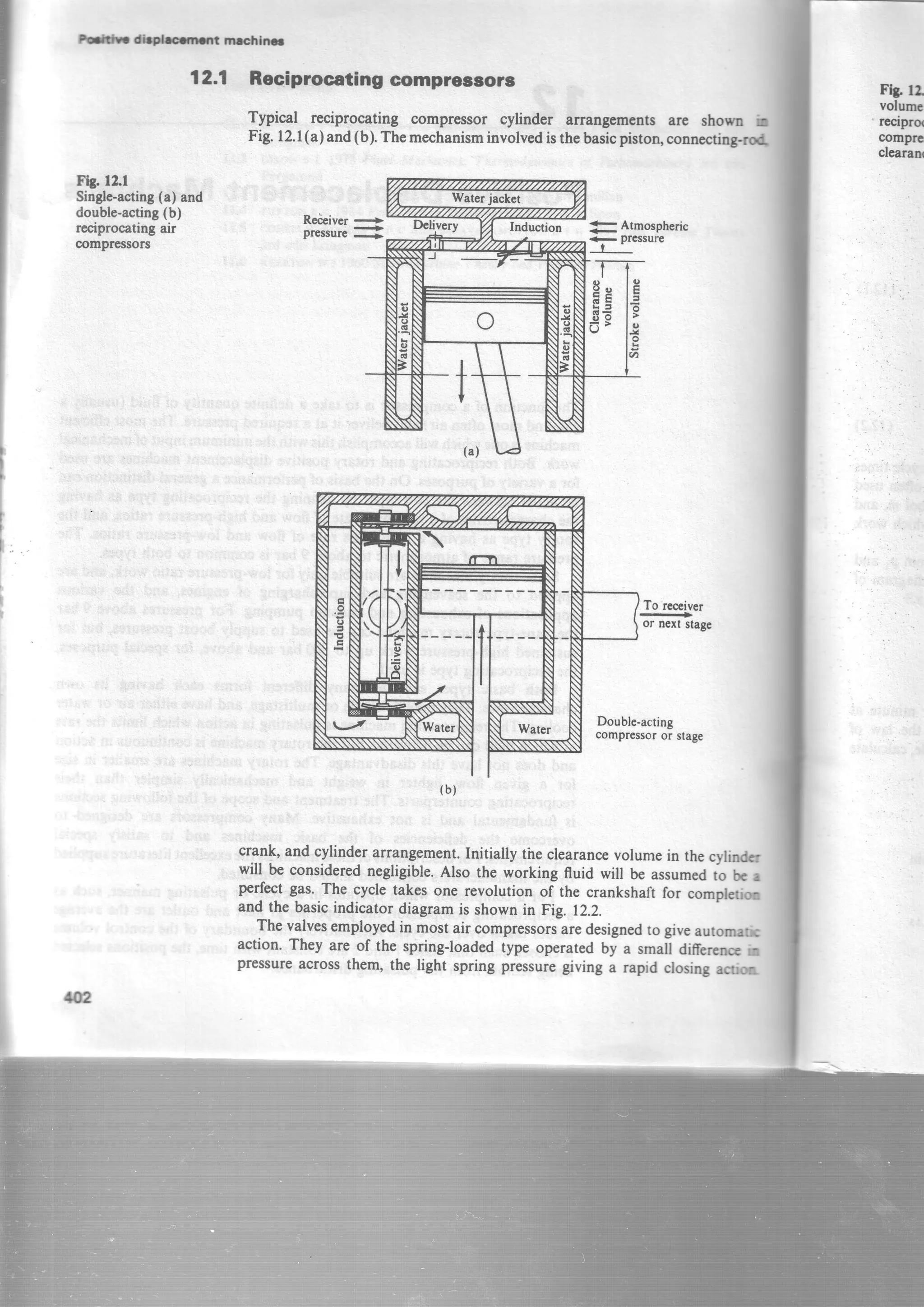
A reciprocating compressor takes in a gas and delivers it at a higher pressure through the cyclic action of pistons in cylinders. There are two main types - single-acting and double-acting. The compression process can follow different thermodynamic paths like isothermal, polytropic, or isentropic on a pressure-volume or temperature-entropy diagram. Isothermal compression provides the minimum work and highest efficiency. The indicated power and efficiency of a reciprocating compressor depends on parameters like mass flow rate, inlet and outlet pressures and temperatures, and the compression process path.
![rork
Jra0i
[o',
I
Ld
F.
f : t r
!
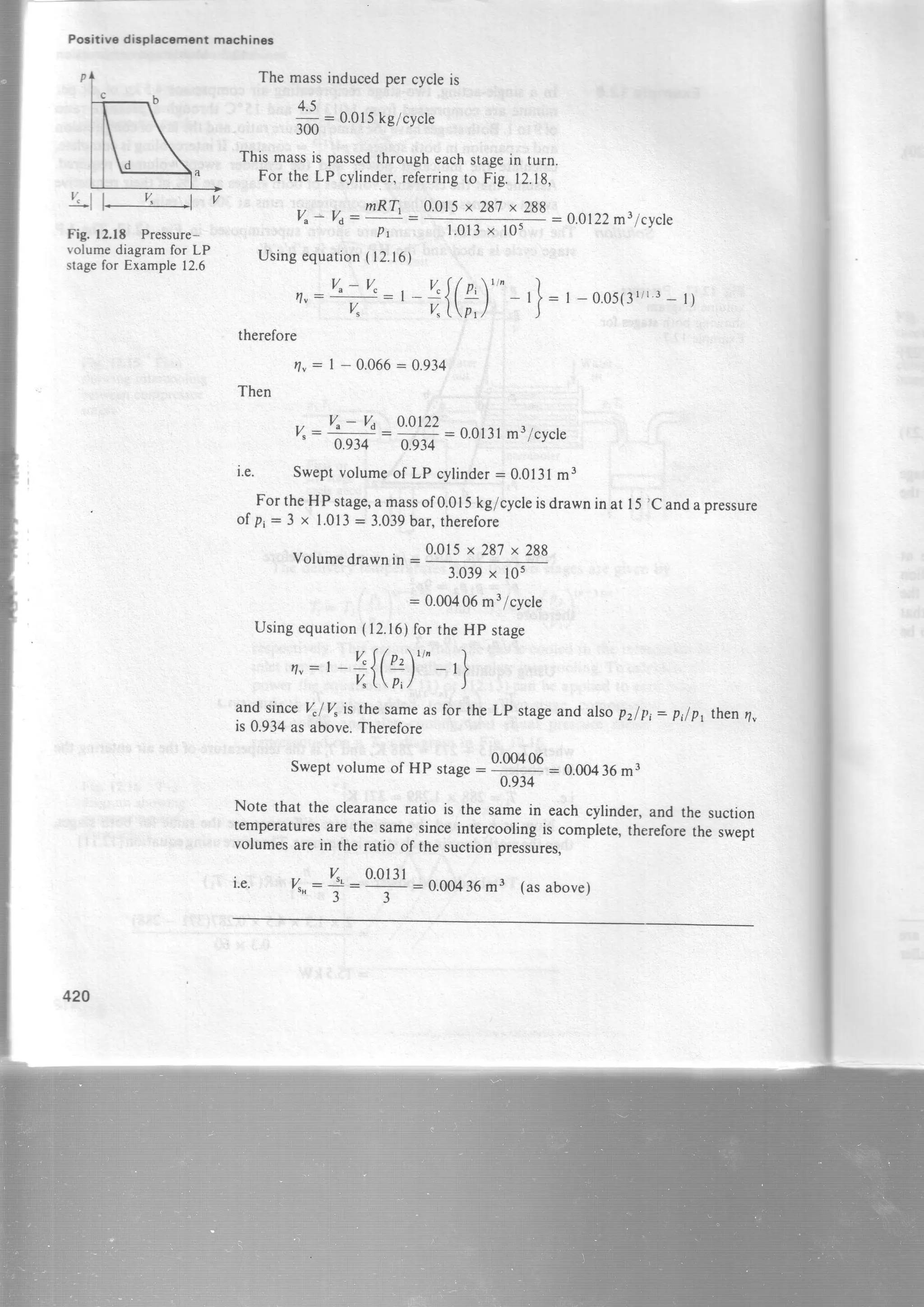
Fg. 12.4 Possible
compressionprocesses
on a p-v diagram
Example12.3
indicatedworkpercycle: p2V6,lnPf,
= PrVrhA
Pt
: mRThU
(12"8)
(l2.e)
(lzt0)
isothermalemAaryd fu
12.1 RcciwocdilrO compr=.t
p
Pz
plz] = const.
pZ'= const.
pZ : const.
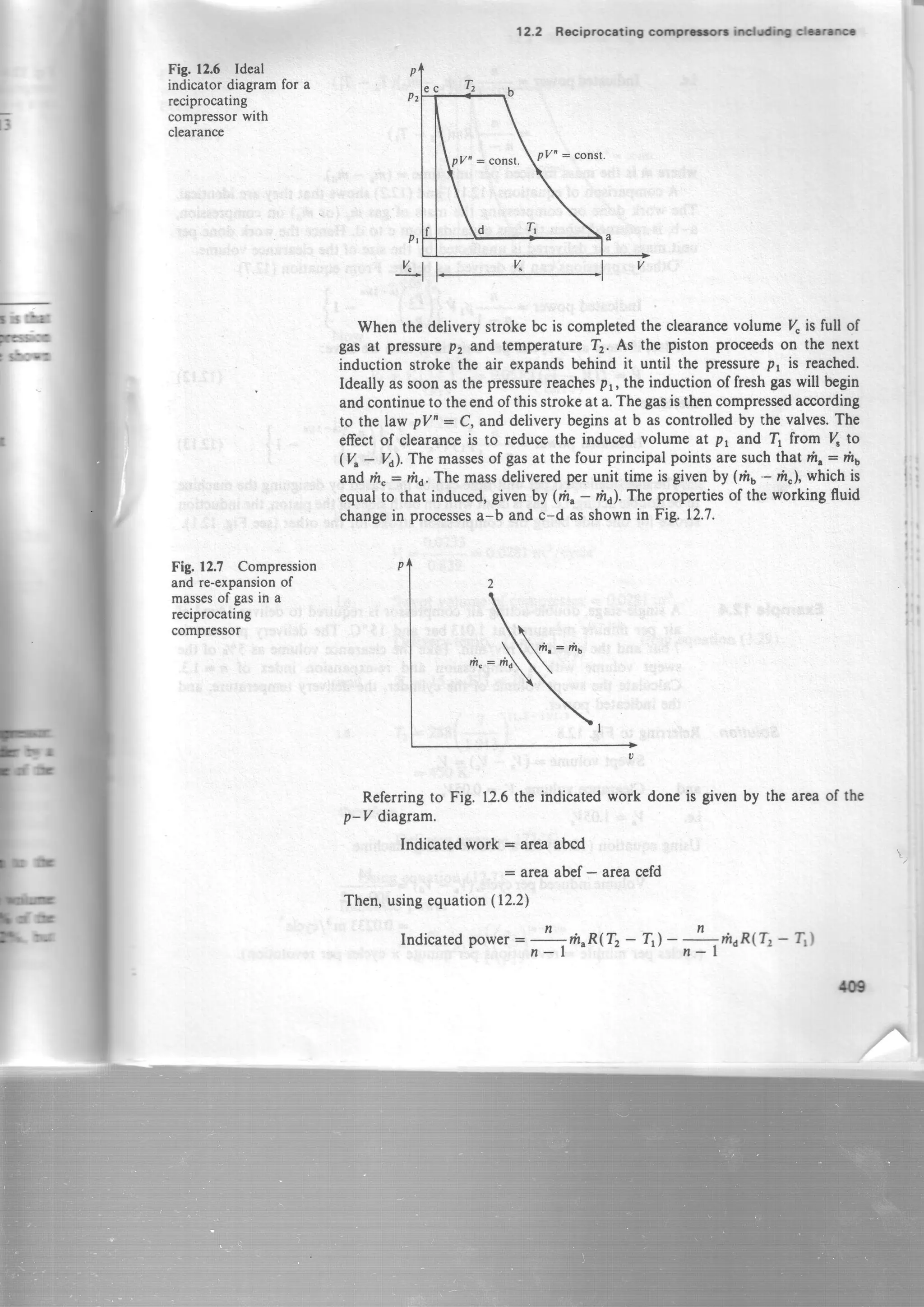
compressorthe gastemp€raturemust be kept ascloseaspossibleto its initial
value,andameansofcoolingthegasisalwaysprovided,eitherbyairor bywater.
The indicatedwork done when the gasis compressedisothermallyis givcn
by the areaablcd.
Area ablcd : ateaabref+ areabrc0e- areaad0f
Areaablef: pzVa,6& lfrom equation(3.9))'
Pr
i.e. indicatedwork perclcle= p2V6,ln!2* PtVt,- PrV"
P t
Alsop1Vr: p276,,sincethe processab1is isothermal,therefore
Pt
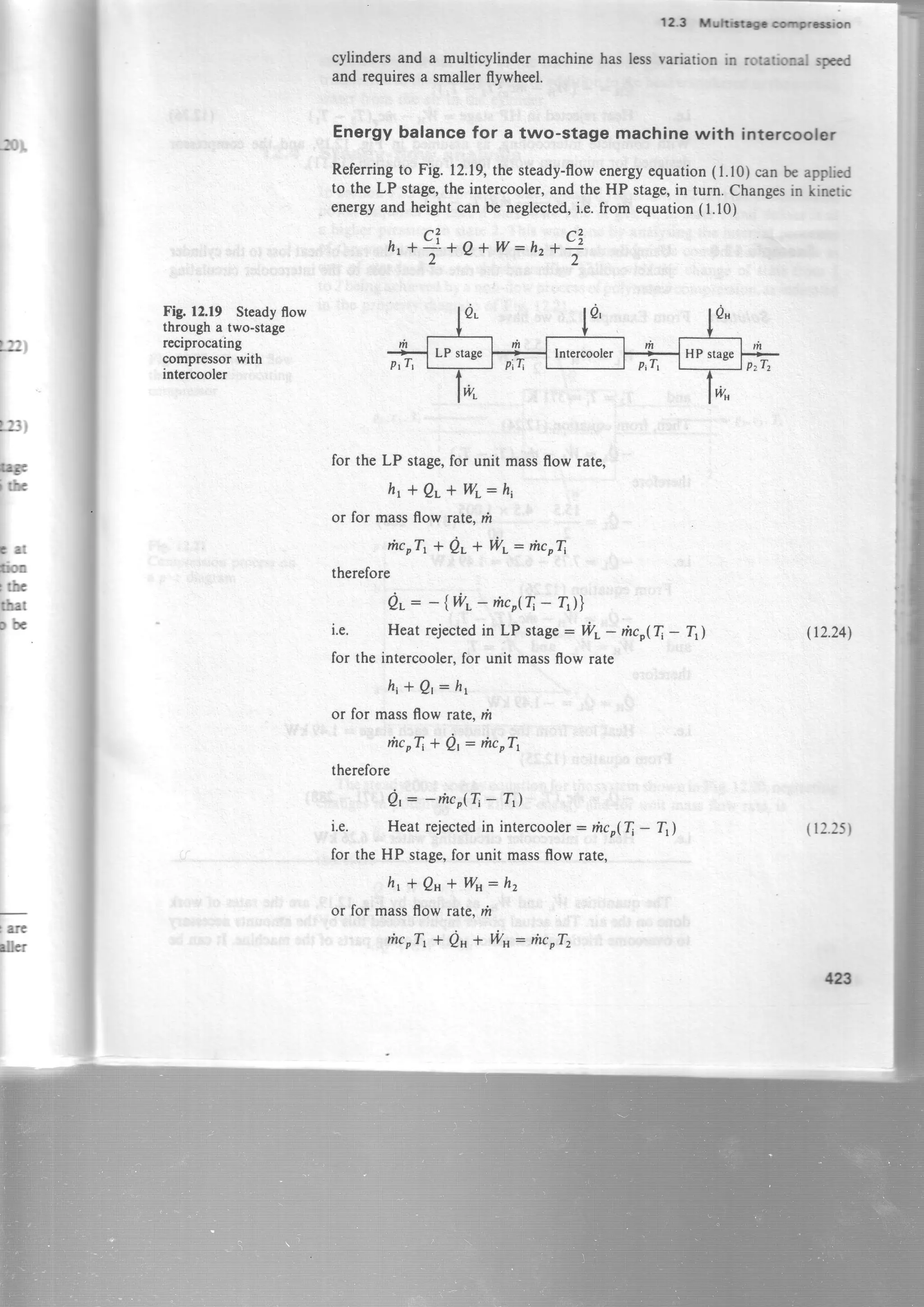
Whenm and %in equations(12.8)and(12.9)arethemassandvolumeinduccd
per unit time, then theseequationsgivethe isothermalpower.
lsothermal efficiency
By definition,basedon the indicator diagram
isothermalwork
,tv43
EI
Isothermalefficiency:
Using the data of Example
compressor.
indicatedwork
l2.l calculatethe
t3](https://image.slidesharecdn.com/appliedthermodynamicsbymcconkeyed-5ch-12-160125200518/75/Applied-thermodynamics-by-mc-conkey-ed-5-ch-12-7-2048.jpg)


![Pooitive dispt.camslt rnachincc
Totalminimumpower:2 x (powerrequiredfor onestage)
:2 rrfrRr,i(A)'"-"'"- ,]
n-l tp'l )
or in termsoftheoverallpressureratiop,I p, ,wehave,usingequation(12.20|
p,_J;; _ la
P r P t V P t
therefore
rotalminimumpower:,,i*{(f)'"-""" -
This can be shownto extendto z stagesgiving in general,
rotalminimumpower= r-!-,antte)" "'""-'] tr2'22)
Pressureratioforeachstage:(fi)"'
'l
(12.23)
Hencethecondition for minimum work is that the pressureratio in eachstage
is the sameand that intercoolingis complete.(Note that in Example12.6the
information givenimpliesminimum work')
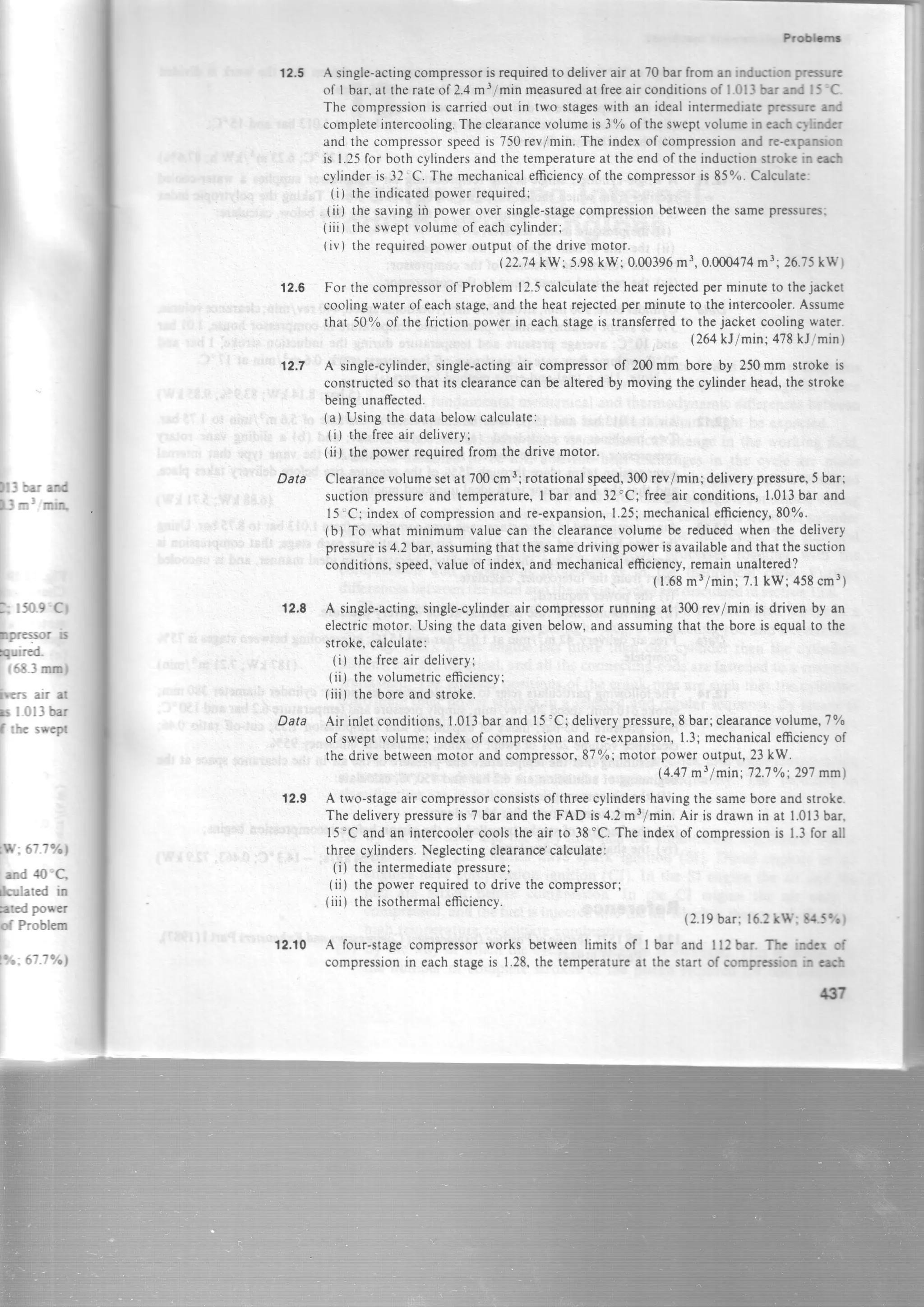
Example 12.7 A three-stage,single-actingair compressorrunning in an atmosphereat
t.0t3bar uiO tst tur a freeair deliveryof 2.83m3/min.The suction
pressureand temperatureare0.98bar and 32'C respectively.Calculatethe
indicatedpoweriequired,assumingcompleteintercooling n: 1.3,and that
the machineis designedfor minimum work. The deliverypressureis to be
70bar.
1.013x tos-I?'gt : i.47kg/minSolution Massof air delivercd- 1Y=:
RT
whereT=15*273:288K.
Thcnusingequation(12.221
TotalindicatedPower
287x288
=,{an"te)""'"-,}
=, *
H "
ry.9;ig{(#)"
rY(3x13}
- r}
=24.2kW
Besidesthe benefitsof multistagecompressionalreadydealt with thereare
also mechanicaladvantages.The higher pressuresare confinedto the smaller
422
F?
thrt
rcdt
ooE
intc](https://image.slidesharecdn.com/appliedthermodynamicsbymcconkeyed-5ch-12-160125200518/75/Applied-thermodynamics-by-mc-conkey-ed-5-ch-12-22-2048.jpg)


![lEi
' rt2lf
Irod]ai
Thtrr-
iroiH
l i l
dq
-
3pth
C
tur-l
rcT
pt ir &t
lir.*d
FE$r
i:r*r
hrl r
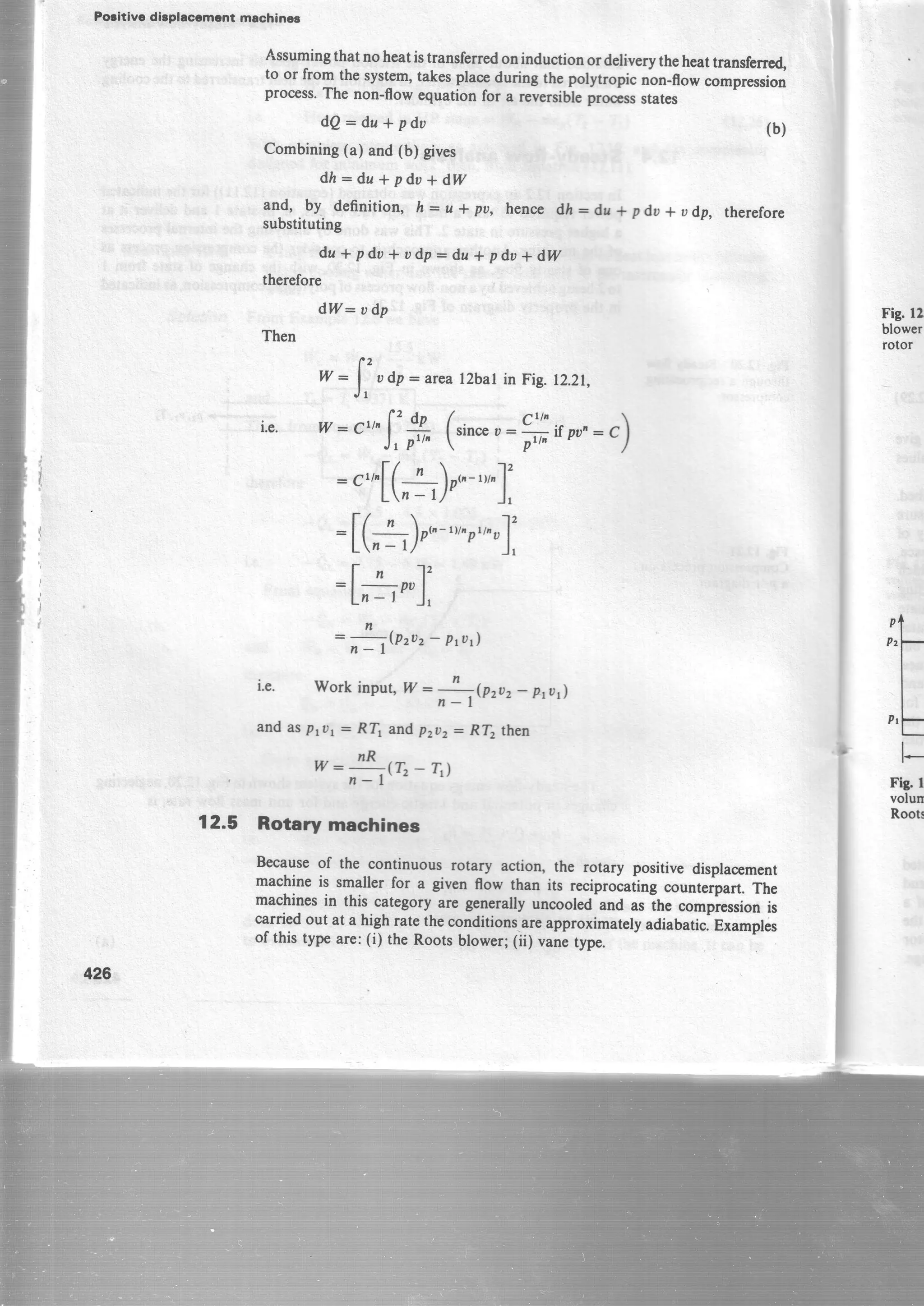
Fig 12.24 Vane-type
positivedisplacement
compressor
F.ry.12,25 Pressure-
volumediagramfor a
YAne-typecompressor
Example 12.9
Solution
12.6 nArr rn*r
IEl,
Krq
t n ,
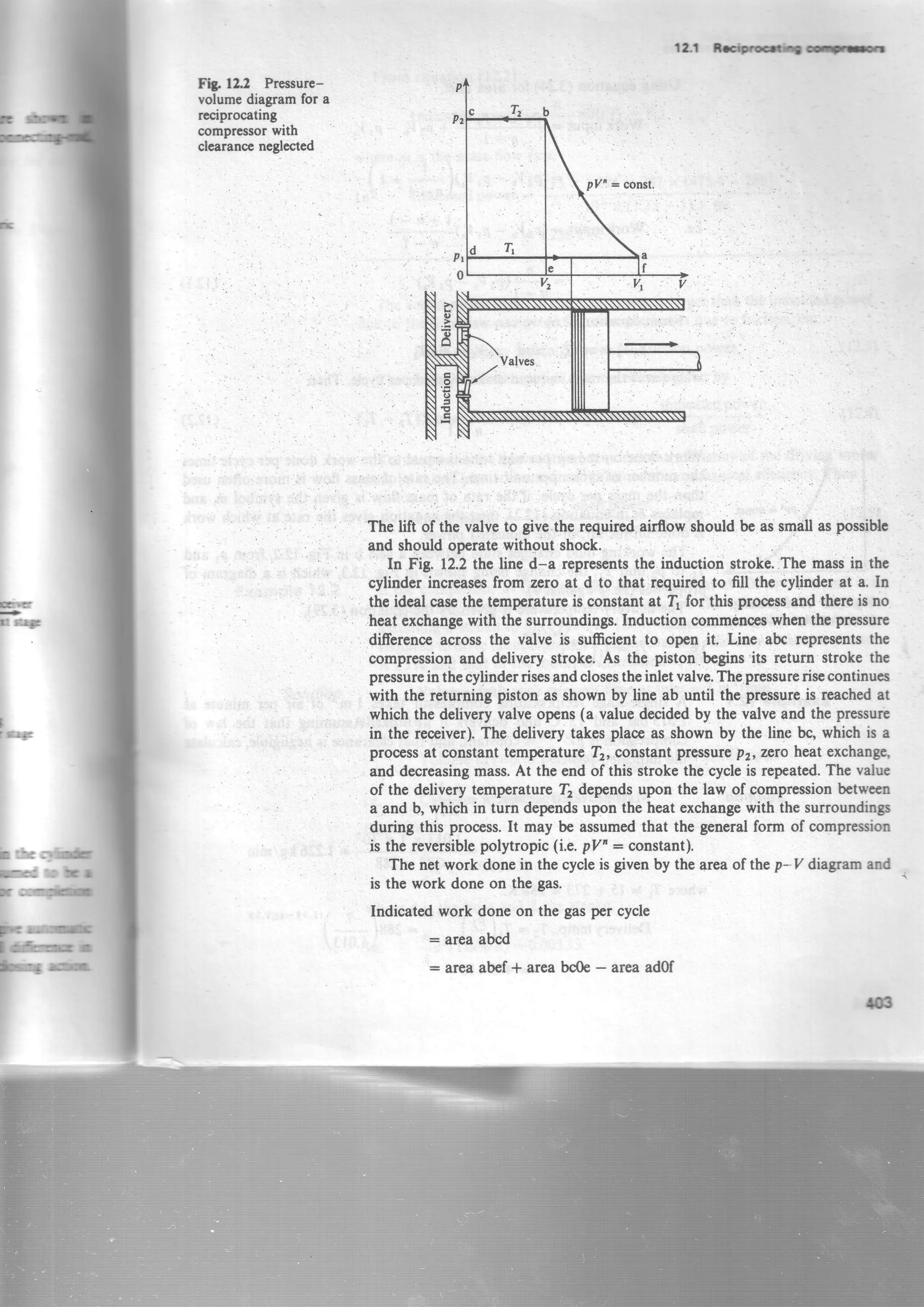
This type of compressiondiffersfrom that of the Rootsblowerin that someor
all of the compressionis obtained beforethe trapped volume is openedto
delivery.Further compressioncanbeobtaineduy ttri back-flowof air from the
receiverwhich occursin an irreversiblemanner.
Thep-v diagramis shownin Fig. rz.2s.v"is theinducedvolumear pressure
pr and temperature[. compressionoccursto the pressurep,, thc idealform
for an uncooledmachinebeingisentropic.At this prissurethl'displacedgasis
openedto thereceiverandgasflowing backfrom thereceiverraisejtheprJrrur"
irr-eversiblyto pr. The work input is given by the sum of the areasA and B,
referringto Fig. 12.25.comparing the areasof Figs 12.23and 12.2sit can be
seenthat for a given airflow and given pressureratio the vanetyp€ requires
lesswork input than the Roots blower.
A rotary slidingvanetwo-stagemachineis shownin Fig. 12.26;inthis typc
the vanesare in contact with the cylinder walls.
compare the work inputs required for a Roots blower and a yane-typc
compressorhavingthesameinducedvolumeof 0.03m3/rev,theinlct prc rc
being 1.013bar and the pressureratio 1.5to l. For the vaoetypc ernc
that internal compressiontakesplacethrough half the pressurerrqla
Pr : 1.013bar](https://image.slidesharecdn.com/appliedthermodynamicsbymcconkeyed-5ch-12-160125200518/75/Applied-thermodynamics-by-mc-conkey-ed-5-ch-12-29-2048.jpg)