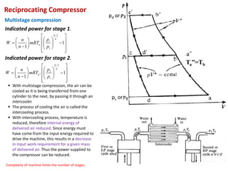
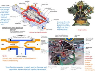
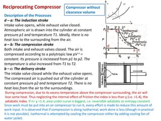
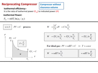
The lecture by Dr. Shibayan Sarkar covers compressors, emphasizing their role in increasing air pressure for various applications such as automotive services and spray painting. It details different types of compressors, including positive displacement and centrifugal types, and explains the mechanics of reciprocating compressors, including their efficiency metrics and cycle of operation. Additionally, the lecture addresses the significance of clearance volume and its impact on compressor performance, highlighting efficiencies and related calculations.


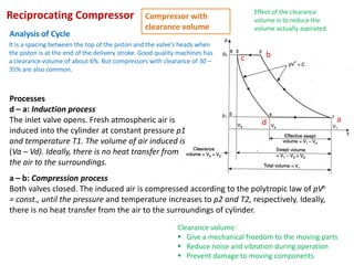

![Reciprocating Compressor Compressor with
clearance volume
a
b
c
d
( )
1
2
1 1 4
1
1
1
n
n
p
n
W p V V
n p
−
= − −
−
Assuming polytropic index to be same
for both compression and clearance
expansion Indicated work / cycle =
1 1
3
2
1 1 4 4
1 4
1 1
1 1
n n
n n
p
p
n n
W p V p V
n p n p
− −
− − −
− −
But p4=p1, p3=p2 therefore
( ) [ ]
2 1
1
a d
n
W m m R T T
n
= − −
−
Volumetric efficiency =
1 4 1 4
1 3
1 2
1/
2 1
1/
3 4
1 ( / )
1 ( / )
1 ( / )
s
n
n
V V V V
V V V
k k V V
k k p p
k k p p
− −
=
−
= + −
= + −
= + −
Where, k=clearance ratio = V3/(V1-V3)=Vc/Vs
Ratio has a value 4% - 10 %
The greater is the clearance ratio
through a reciprocating
compressor, the greater will be the
effect of the clearance volume
since the clearance air will expand
through greater volume before
intake condition is reached.](https://image.slidesharecdn.com/lv597frxtukdfj4zeztn-mmc-16101-compressor-01-240419055311-ca0ac314/85/ProjectreportMMC_16101_compressor_01-pdf-20-320.jpg)