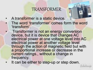
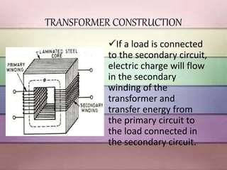
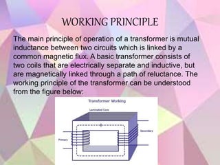
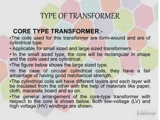
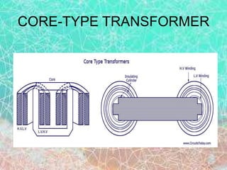
TRANSFORMER
S
DJJ2022: ELECTRICAL TECHNOLOGY
PUAN FARIDAH BT. SALLEH
PRESENTED BY:
• NURAIMI KHAIRINA BT YASMIN
01DKM14F1138
• SITI ZULAIKA BT ISMAIL
01DKM14F1130
• VINAASHA A/P BALAKRISHNAN
01DKM14F1113
• SARAH BT MD AROFF
01DKM14F1143
TRANSFORMER
• A transformer is a static device.
• The word ‘transformer’ comes form the word
‘transform’.
• Transformer is not an energy conversion
device, but it is device that changes AC
electrical power at one voltage level into AC
electrical power at another voltage level
through the action of magnetic field but with
a proportional increase or decrease in the
current ratings., without a change in
frequency.
• It can be either to step-up or step down.
TRANSFORMER CONSTRUCTION
If a load is connected
to the secondary circuit,
electric charge will flow
in the secondary
winding of the
transformer and
transfer energy from
the primary circuit to
the load connected in
the secondary circuit.
WORKING PRINCIPLE
The main principle of operation of a transformer is mutual
inductance between two circuits which is linked by a
common magnetic flux. A basic transformer consists of
two coils that are electrically separate and inductive, but
are magnetically linked through a path of reluctance. The
working principle of the transformer can be understood
from the figure below:
TYPE OF TRANSFORMER
CORE TYPE TRANSFORMER:-
•The coils used for this transformer are form-wound and are of
cylindrical type.
• Applicable for small sized and large sized transformers.
• In the small sized type, the core will be rectangular in shape
and the coils used are cylindrical.
•The figure below shows the large sized type.
•In the case of circular cylindrical coils, they have a fair
advantage of having good mechanical strength.
•The cylindrical coils will have different layers and each layer will
be insulated from the other with the help of materials like paper,
cloth, macerate board and so on.
•The general arrangement of the core-type transformer with
respect to the core is shown below. Both low-voltage (LV) and
high voltage (HV) windings are shown.
CORE-TYPE TRANSFORMER
SHELL-TYPE TRANSFORMER
• The coils are form-wound but are multi layer disc
type usually wound in the form of pancakes.
• Paper is used to insulate the different layers of
the multi-layer discs.
• The whole winding consists of discs stacked with
insulation spaces between the coils.
• These insulation spaces form the horizontal
cooling and insulating ducts.
• Transformer may have the shape of a simple
rectangle or may also have a distributed form.
In shell-type transformers the core
surrounds a considerable portion of the
windings. The comparison is shown in the
figure below.
STEP-UP TRANSFORMER
• In a step up transformer,
them number of turns in
secondary
coil (Ns) is greater than
that of primary coil( Np).
• The primary coil is made
of a thick insulated
copper wire ,while
secondary coil of thin
insulated wire. It converts
low voltage at high
current into high voltage
at low current.
STEP-DOWN TRANSFORMER
• In a step-down
transformer the number
of turns in seondary coil
(Ns) is less than that in
primary coil(Np).
• In a step-down
transformer ,the primary
coil is made of a thin
wire and the secondary
coil of thick wire.It
converts a high voltage
at low current into a low
voltage at high current
APPLICATIONS
• A step-down
transformer is used for
obtaining large current
for electric welding.
• A step-down
transformer is used in
induction furnace for
melting the metals.
• A step-up transformer
is used for the
production of X-rays.
• Transformers are used
in voltage regulators
and stabilised power
supplies.
ENERGY LOSSES IN A TRANSFORMER
• TYPES OF ENERGY LOSSES
i. Flux losses
ii. Copper losses
iii. Iron losses
iv. Hysteresis losses
•COPPER LOSS
Transformer Efficiency
• To check the performance of the device,
by comparing the output with respect to
the input.
• The higher the efficiency, the better the
system.
Faraday’s Law
 Faraday’s law states that:
Vs=Ns.dΦ/dt
 where VS is the instantaneous voltage.
 NS is the number of turns in the secondary coil.
 Since the same magnetic flux passes through both
the primary and secondary coils in an ideal
transformer,the instantaneous voltage across the
primary coil
Vp=Np.dΦ/dt
THANK YOU...

ELECTRICAL TECHNOLOGY- Transformers

  • 1.
  • 2.
    DJJ2022: ELECTRICAL TECHNOLOGY PUANFARIDAH BT. SALLEH PRESENTED BY: • NURAIMI KHAIRINA BT YASMIN 01DKM14F1138 • SITI ZULAIKA BT ISMAIL 01DKM14F1130 • VINAASHA A/P BALAKRISHNAN 01DKM14F1113 • SARAH BT MD AROFF 01DKM14F1143
  • 3.
    TRANSFORMER • A transformeris a static device. • The word ‘transformer’ comes form the word ‘transform’. • Transformer is not an energy conversion device, but it is device that changes AC electrical power at one voltage level into AC electrical power at another voltage level through the action of magnetic field but with a proportional increase or decrease in the current ratings., without a change in frequency. • It can be either to step-up or step down.
  • 4.
    TRANSFORMER CONSTRUCTION If aload is connected to the secondary circuit, electric charge will flow in the secondary winding of the transformer and transfer energy from the primary circuit to the load connected in the secondary circuit.
  • 5.
    WORKING PRINCIPLE The mainprinciple of operation of a transformer is mutual inductance between two circuits which is linked by a common magnetic flux. A basic transformer consists of two coils that are electrically separate and inductive, but are magnetically linked through a path of reluctance. The working principle of the transformer can be understood from the figure below:
  • 6.
    TYPE OF TRANSFORMER CORETYPE TRANSFORMER:- •The coils used for this transformer are form-wound and are of cylindrical type. • Applicable for small sized and large sized transformers. • In the small sized type, the core will be rectangular in shape and the coils used are cylindrical. •The figure below shows the large sized type. •In the case of circular cylindrical coils, they have a fair advantage of having good mechanical strength. •The cylindrical coils will have different layers and each layer will be insulated from the other with the help of materials like paper, cloth, macerate board and so on. •The general arrangement of the core-type transformer with respect to the core is shown below. Both low-voltage (LV) and high voltage (HV) windings are shown.
  • 7.
  • 8.
    SHELL-TYPE TRANSFORMER • Thecoils are form-wound but are multi layer disc type usually wound in the form of pancakes. • Paper is used to insulate the different layers of the multi-layer discs. • The whole winding consists of discs stacked with insulation spaces between the coils. • These insulation spaces form the horizontal cooling and insulating ducts. • Transformer may have the shape of a simple rectangle or may also have a distributed form.
  • 9.
    In shell-type transformersthe core surrounds a considerable portion of the windings. The comparison is shown in the figure below.
  • 10.
    STEP-UP TRANSFORMER • Ina step up transformer, them number of turns in secondary coil (Ns) is greater than that of primary coil( Np). • The primary coil is made of a thick insulated copper wire ,while secondary coil of thin insulated wire. It converts low voltage at high current into high voltage at low current.
  • 11.
    STEP-DOWN TRANSFORMER • Ina step-down transformer the number of turns in seondary coil (Ns) is less than that in primary coil(Np). • In a step-down transformer ,the primary coil is made of a thin wire and the secondary coil of thick wire.It converts a high voltage at low current into a low voltage at high current
  • 12.
    APPLICATIONS • A step-down transformeris used for obtaining large current for electric welding. • A step-down transformer is used in induction furnace for melting the metals. • A step-up transformer is used for the production of X-rays. • Transformers are used in voltage regulators and stabilised power supplies.
  • 13.
    ENERGY LOSSES INA TRANSFORMER • TYPES OF ENERGY LOSSES i. Flux losses ii. Copper losses iii. Iron losses iv. Hysteresis losses
  • 14.
  • 15.
    Transformer Efficiency • Tocheck the performance of the device, by comparing the output with respect to the input. • The higher the efficiency, the better the system.
  • 16.
    Faraday’s Law  Faraday’slaw states that: Vs=Ns.dΦ/dt  where VS is the instantaneous voltage.  NS is the number of turns in the secondary coil.  Since the same magnetic flux passes through both the primary and secondary coils in an ideal transformer,the instantaneous voltage across the primary coil Vp=Np.dΦ/dt
  • 17.