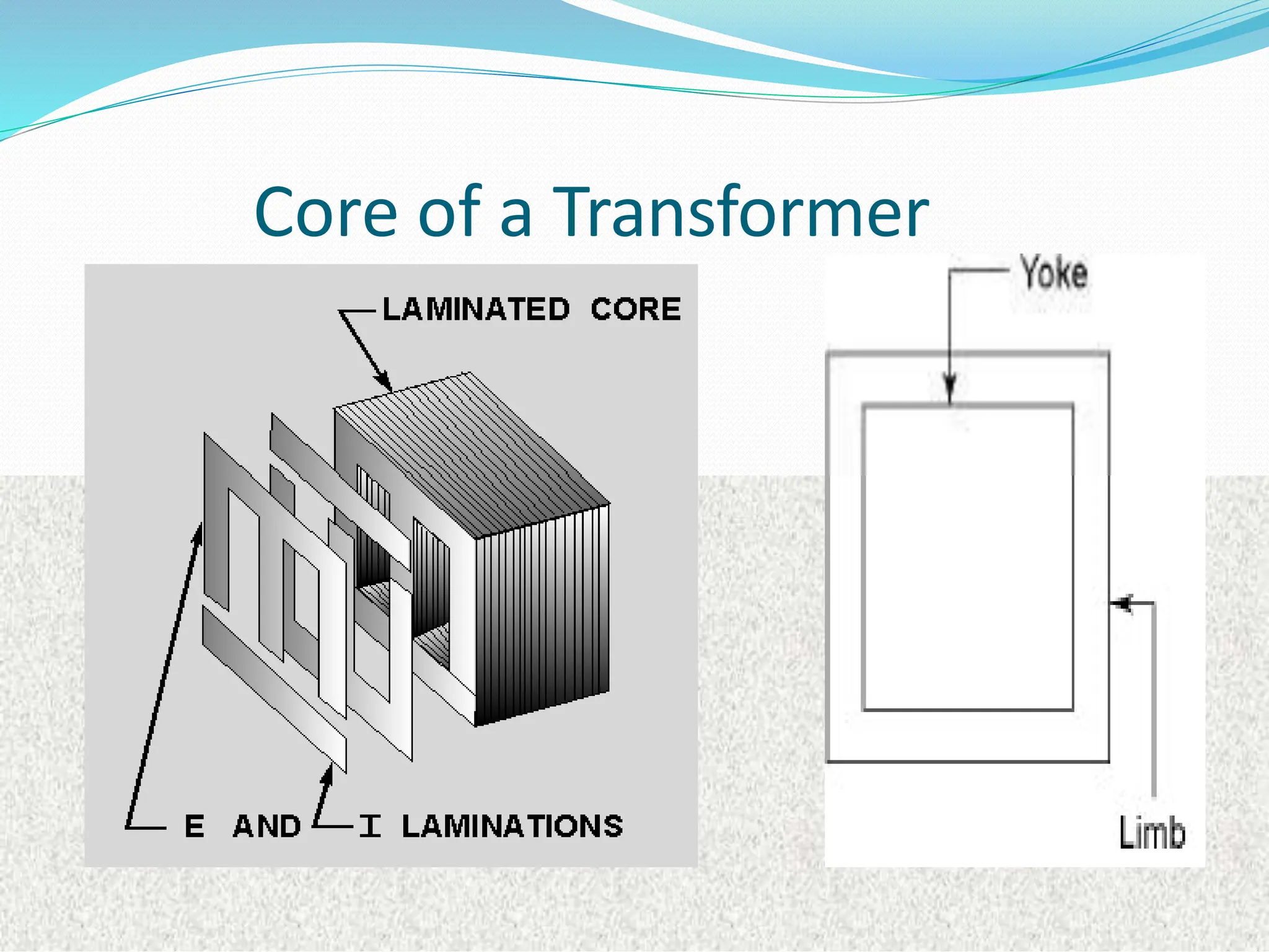
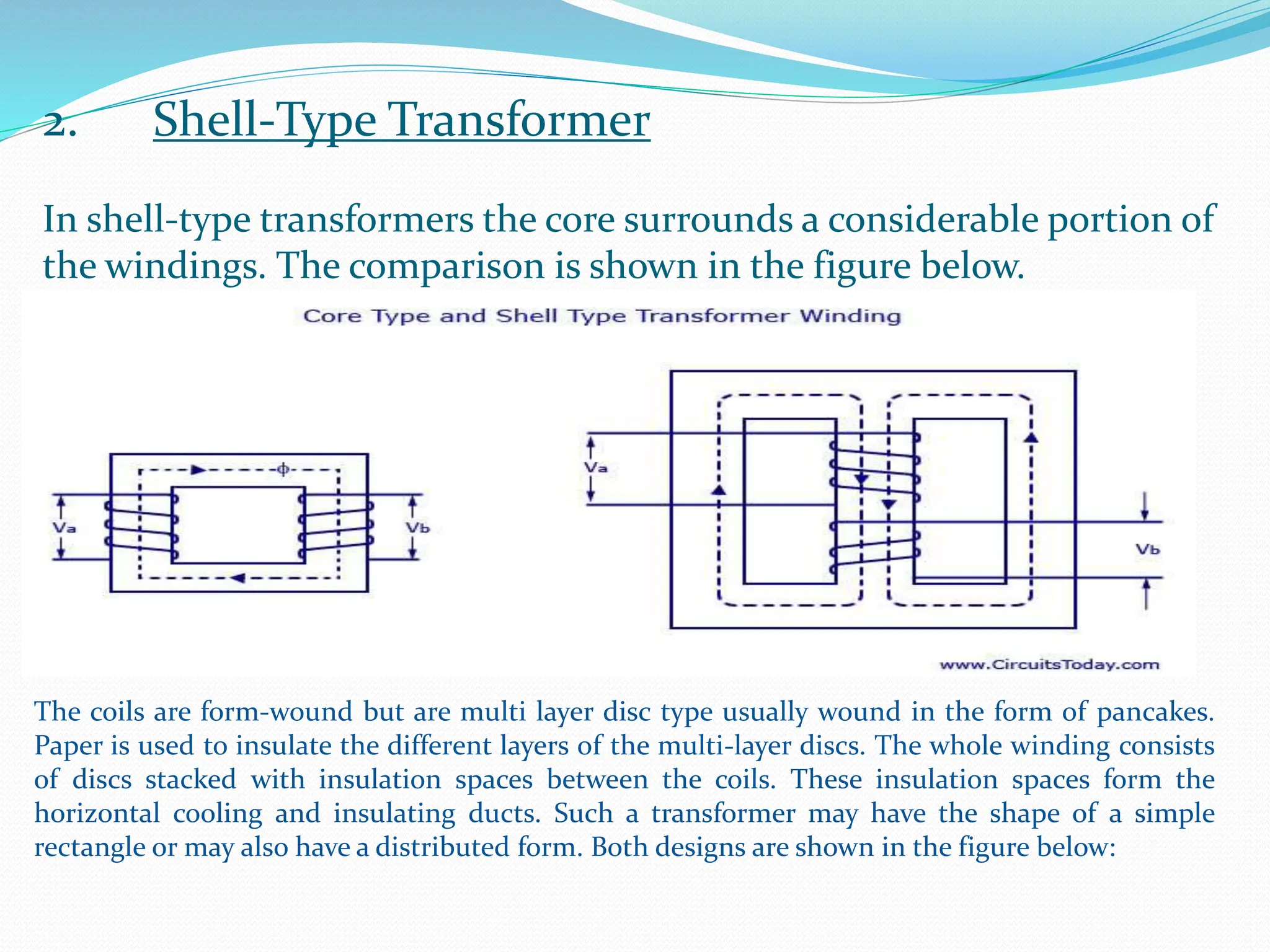
Transformer - Definition
Transformer is a static device by means of
which an electric power in one circuit is
transformed to other circuit, without change
in frequency.
It can increase or decrease the voltage in a
circuit but with a corresponding decrease or
increase in current.
Basic Working Principle
Mutual Induction between two
circuits linked by a common
magnetic flux.
Faraday’s Law of Electromagnetic
Induction
“whenever a conductor is
placed in a varying magnetic field,
emf is induced in it, which is called
induced emf. If the conductor
circuit are closed, current is also
induced which is called induced
current.”.
Transformer Representation
Working Principle of Transformer
 In Transformer, there are two inductive coils,
which are electrically separated and magnetically
coupled.
 If one coil is connected to ac source  an
alternating flux is set up in the core  it links with
other coil and produced mutually induced emf
(Faraday’s Law).
 If the second coil is closed, current flows in it – Thus
Energy is transferred.
 First Coil  Primary and Second Coil 
 Secondary
TRANSFORMER
• A transformer is a static device.
• The word ‘transformer’ comes form the word ‘transform’.
• Transformer is not an energy conversion device, but it is device that changes
electrical power at one voltage level into electrical power at another voltage
level through the action of magnetic field but with a proportional increase or
decrease in the current ratings., without a change in frequency.
• It can be either to step-up or step down.
TYPES OF TRANSFORMER
STEP UP TRANSFORMER:
A transformer in which voltage across
secondary is greater than primary voltage
is called a step-up transformer (shown in
figure)
In this type of transformer, Number of
turns in secondary coil is greater than that
in Primary coil, so this creates greater
voltage across secondary coil to get more
output voltage than given through primary
coil.
TYPES OF TRANSFORMER
STEP DOWN TRANSFORMER:
•A transformer in which voltage across
secondary is lesser than primary voltage is
called a step-down transformer (shown in
figure)
•In this type of transformer, Number of
turns in secondary coil is lesser than that in
Primary coil, so this creates lesser voltage
across secondary coil, so we get low
output voltage than given through primary
coil.
The transformer works in the principle of mutual induction
“The principle of mutual induction states that when the two
coils are inductively coupled and if the current in coil change
uniformly then the e.m.f. induced in the other coils. This e.m.f
can drive a current when a closed path is provide to it.”
When the alternating current flows in the primary coils, a changing magnetic
flux is generatedaround the primary coil.
The changing magnetic flux is transferred to the secondary coil through the iron
core
The changing magnetic flux is cut by the secondary coil, hence induces an e.m.f
in the secondary coil
WORKING
Now if load is connected to a secondary winding, this e.m.f drives a current
through it
The magnitude of the output voltage can be controlled by the ratio of the
no. of primary coil and secondary coil
The frequency of mutually induced e.m.f as same that of
the alternating source which supplying to the primary
winding b
 For the simple construction of a transformer, you must need two coils having
mutual inductance and a laminated steel core. The two coils are insulated
from each other and from the steel core. The device will also need some
suitable container for the assembled core and windings, a medium with
which the core and its windings from its container can be insulated.
 In order to insulate and to bring out the terminals of the winding from the
tank, apt bushings that are made from either porcelain or capacitor type must
be used.
 In all transformers that are used commercially, the core is made out of
transformer sheet steel laminations assembled to provide a continuous
magnetic path with minimum of air-gap included. The steel should have high
permeability and low hysteresis loss. For this to happen, the steel should be
made of high silicon content and must also be heat treated. By effectively
laminating the core, the eddy-current losses can be reduced. The lamination
can be done with the help of a light coat of core plate varnish or lay an oxide
layer on the surface. For a frequency of 50 Hertz, the thickness of the
lamination varies from 0.35mm to 0.5mm for a frequency of 25 Hertz.
Transformer Construction
• Core :
♦ Carries the flux produced by the winding
♦ It is either square or rectangular shape.
♦ The vertical portion of the core is called Limb
♦ The top and bottom horizontal portion of the core is
called Yoke.
♦ Made of high grade silicon steel laminations
♦ Laminated arrangements reduces eddy current losses.
♦ The laminations are insulated from each other by
using insulation like varnish.
Core of a Transformer
Transformer Construction
• Windings:
Coils used are wound on the limbs and insulated
from each other.
Windings carry the current and produce the
necessary flux
Primary and Secondary coils are insulated from
each other.
Coils are made up of Copper.
Windings of a Transformer
Conservator : takes up the expansion and
contraction of the oil without allowing it to
come in contact with the ambient air.
Explosion Vent :
A bent
air (using
Breather :
Extracts the
moisture from
silica
gel crystals) and
does not allow
oil to come in
contact with the
moisture.
fitted
tank,
bursts
pressure
pipe
on main
which
when
inside
the transformer
becomes
excessive (which
releases the
pressure and
protects the
transformer)
Types of Single Phase
Transformers
Core Type Transformer
Shell Type Transformer
1. Core Type Transformers
 Single Magnetic Circuit with 2 Limbs – Windings
placed on both the limbs  Winding encircles the
core.
 Cylindrical type coils are used with each layers
insulated by paper or mica.
 Low voltage coil is placed near the core and High
voltagecoil surrounds the low voltagecoil.
 Natural cooling is more effective.
 Coils can be easily removed by removing the
laminations of the tope yoke, for maintenance
2. Shell Type Transformers
Double Magnetic Circuit with 3 Limbs –
Windings placed on central limb  Core
encircles most part of the windings.
Natural Cooling doesn’t exist
Difficult for maintenance, as for removing any
winding, large laminations to be removed
Preferred for Very High Voltage Transformers.
Comparison of Core and Shell
Type Transformers
Classification of Transformer
• As per phase
1. single phase
2. Three phase
• As per core
1. Core type
2. Shell type
• As per cooling system
1. Self-cooled
2. Air cooled
3. Oil cooled
Three phase transformer
Normally , when three-phase is required, a single enclosure with three
primary and three secondary windings wound on a common core is all that
is required. However three single-phase transformers with the same rating
can be connected to form a three-phase bank. Since each single-phase
transformer has a primary and a secondary winding, then 3 single-phase
transformers will have the required 3 primary and 3 secondary windings and
can be connected in the field either Delta-Delta or Delta-Wye to
achieve the required three-phased transformer bank
Transformer classified
as per core
 CORE TYPE TRANSFORMER:-
In core-type transformer, the windings are given to a
considerable part of the core. The coils used for this transformer are form-wound and are of
cylindrical type. Such a type of transformer can be applicable for small sized and large sized
transformers. In the small sized type, the core will be rectangular in shape and the coils used are
cylindrical. The figure below shows the large sized type. You can see that the round or cylindrical
coils are wound in such a way as to fit over a cruciform core section. In the case of circular
cylindrical coils, they have a fair advantage of having good mechanical strength. The cylindrical
coils will have different layers and each layer will be insulated from the other with the help of
materials like paper, cloth, macerate board and so on. The general arrangement of the core-type
transformer with respect to the core is shown below. Both low-voltage (LV) and high voltage (HV)
windings are shown.
The low voltage windings are placed nearer to the core as it is
the easiest to insulate. The effective core area of the
transformer can be reduced with the use of laminations and
insulation
2. Shell-Type Transformer
In shell-type transformers the core surrounds a considerable portion of
the windings. The comparison is shown in the figure below.
The coils are form-wound but are multi layer disc type usually wound in the form of pancakes.
Paper is used to insulate the different layers of the multi-layer discs. The whole winding consists
of discs stacked with insulation spaces between the coils. These insulation spaces form the
horizontal cooling and insulating ducts. Such a transformer may have the shape of a simple
rectangle or may also have a distributed form. Both designs are shown in the figure below:
A strong rigid mechanical bracing must be given to the cores and coils of the transformers. This will
help in minimizing the movement of the device and also prevents the device from getting any
insulation damage. A transformer with good bracing will not produce any humming noise during its
working and will also reduce vibration.
A special housing platform must be provided for transformers. Usually, the device is placed in tightly-
fitted sheet-metal tanks filled with special insulating oil. This oil is needed to circulate through the
device and cool the coils. It is also responsible for providing the additional insulation for the device
when it is left in the air.
CLASSIFICATION ON THE BASIS OF
COOLING EMPLOYED
 1. Oil Filled Self-Cooled Type
 Oil filled self cooled type uses small and medium-sized distribution transformers. The assembled
windings and core of such transformers are mounted in a welded, oil-tight steel tanks provided with a
steel cover. The tank is filled with purified, high quality insulating oil as soon as the core is put back at
its proper place. The oil helps in transferring the heat from the core and the windings to the case from
where it is radiated out to the surroundings. For smaller sized transformers the tanks are usually smooth
surfaced, but for large size transformers a greater heat radiation area is needed, and that too without
disturbing the cubical capacity of the tank. This is achieved by frequently corrugating the cases. Still
larger sizes are provided with radiation or pipes.
 2. Oil Filled Water Cooled Type
 This type is used for much more economic construction of large transformers, as the above told self
cooled method is very expensive. The same method is used here as well- the windings and the core are
immersed in the oil. The only difference is that a cooling coil is mounted near the surface of the oil,
through which cold water keeps circulating. This water carries the heat from the device. This design is
usually implemented on transformers that are used in high voltage transmission lines. The biggest
advantage of such a design is that such transformers do not require housing other than their own. This
reduces the costs by a huge amount. Another advantage is that the maintenance and inspection of this
type is only needed once or twice in a year.
 3. Air Blast Type
 This type is used for transformers that use voltages below 25,000 volts. The transformer is housed in a
thin sheet metal box open at both ends through which air is blown from the bottom to the top.
Ideal transformer
 An ideal transformer is a transformer which has no loses, i.e. it’s
winding has no ohmic resistance, no magnetic leakage, and therefore
no I2 R and core loses.
 However, it is impossible to realize such a transformer in practice.
 Yet, the approximate characteristic of ideal transformer will be used in
characterized the practical transformer.
V1 V2
N1 : N2
E1 E2
I1 I2
V1 – Primary Voltage
V2 – Secondary Voltage
E1 – Primary induced Voltage
E2 – secondary induced Voltage
N1:N2 – Transformer ratio
Transformer Efficiency
 To check the performance of the device, by comparing the
output with respect to the input.
 The higher the efficiency, the better the system.
%
100
cos
cos
%
100
%
100
,
2
2
2
2









cu
c
losses
out
out
P
P
I
V
I
V
P
P
P
Power
Input
Power
Output
Efficiency



%
100
cos
cos
%
100
cos
cos
2
)
(
)
(








cu
c
n
load
cu
c
load
full
P
n
P
nVA
nVA
P
P
VA
VA






Where, if ½ load, hence n = ½ ,
¼ load, n= ¼ ,
90% of full load, n =0.9
Where Pcu = Psc
Pc = Poc
Transformer Losses
 Generally, there are two types of losses;
i. Iron losses :- occur in core parameters
ii. Copper losses :- occur in winding resistance
i. Iron Losses
ii Copper Losses
circuit
open
c
c
c
iron P
R
I
P
P 

 2
)
(
02
2
2
01
2
1
2
2
2
1
2
1
)
(
)
(
,
)
(
)
(
R
I
R
I
P
referred
if
or
P
R
I
R
I
P
P
cu
circuit
short
cu
copper






 EDDY CURRENTS
 By Changing Flux through a solid
conductor, induced currents are set up
within the body of a conductor in a
direction perpendicular to the flux
which are eddy currents.
 Since our iron core is ferromagnetic
material, so it allows these currents to
pass through the whole body of
conductor causing heating of core of
conductor.
 This is a power loss in transformer(
shown as in figure 1 ), to reduce this
the core should be made of lamination
sheets which stop the flow of eddy
currents (shown as in figure 2).
 HYSTERESIS LOSS
 The energy spent in magnetisation and
demagnetisation of the core of
transformer is called hysteresis loss.
 This loss in energy is expressed by
using B-H(magnetic flux density B
and flux density H) curve for a
specific ferromagnetic material.
 For reducing this loss, we should use
such a soft material for core whose
hysteresis loop is very small.
 The hysteresis loops of both hard and
soft magnetic materials are shown
respectively, which shows that soft
magnetic materials have small
hysteresis loss of energy.
BYE

transformer and types and construction .pptx

  • 1.
    Transformer - Definition Transformeris a static device by means of which an electric power in one circuit is transformed to other circuit, without change in frequency. It can increase or decrease the voltage in a circuit but with a corresponding decrease or increase in current.
  • 2.
    Basic Working Principle MutualInduction between two circuits linked by a common magnetic flux. Faraday’s Law of Electromagnetic Induction “whenever a conductor is placed in a varying magnetic field, emf is induced in it, which is called induced emf. If the conductor circuit are closed, current is also induced which is called induced current.”.
  • 3.
  • 4.
    Working Principle ofTransformer  In Transformer, there are two inductive coils, which are electrically separated and magnetically coupled.  If one coil is connected to ac source  an alternating flux is set up in the core  it links with other coil and produced mutually induced emf (Faraday’s Law).  If the second coil is closed, current flows in it – Thus Energy is transferred.  First Coil  Primary and Second Coil   Secondary
  • 5.
    TRANSFORMER • A transformeris a static device. • The word ‘transformer’ comes form the word ‘transform’. • Transformer is not an energy conversion device, but it is device that changes electrical power at one voltage level into electrical power at another voltage level through the action of magnetic field but with a proportional increase or decrease in the current ratings., without a change in frequency. • It can be either to step-up or step down.
  • 7.
    TYPES OF TRANSFORMER STEPUP TRANSFORMER: A transformer in which voltage across secondary is greater than primary voltage is called a step-up transformer (shown in figure) In this type of transformer, Number of turns in secondary coil is greater than that in Primary coil, so this creates greater voltage across secondary coil to get more output voltage than given through primary coil.
  • 8.
    TYPES OF TRANSFORMER STEPDOWN TRANSFORMER: •A transformer in which voltage across secondary is lesser than primary voltage is called a step-down transformer (shown in figure) •In this type of transformer, Number of turns in secondary coil is lesser than that in Primary coil, so this creates lesser voltage across secondary coil, so we get low output voltage than given through primary coil.
  • 9.
    The transformer worksin the principle of mutual induction “The principle of mutual induction states that when the two coils are inductively coupled and if the current in coil change uniformly then the e.m.f. induced in the other coils. This e.m.f can drive a current when a closed path is provide to it.” When the alternating current flows in the primary coils, a changing magnetic flux is generatedaround the primary coil. The changing magnetic flux is transferred to the secondary coil through the iron core The changing magnetic flux is cut by the secondary coil, hence induces an e.m.f in the secondary coil WORKING
  • 10.
    Now if loadis connected to a secondary winding, this e.m.f drives a current through it The magnitude of the output voltage can be controlled by the ratio of the no. of primary coil and secondary coil The frequency of mutually induced e.m.f as same that of the alternating source which supplying to the primary winding b
  • 11.
     For thesimple construction of a transformer, you must need two coils having mutual inductance and a laminated steel core. The two coils are insulated from each other and from the steel core. The device will also need some suitable container for the assembled core and windings, a medium with which the core and its windings from its container can be insulated.  In order to insulate and to bring out the terminals of the winding from the tank, apt bushings that are made from either porcelain or capacitor type must be used.  In all transformers that are used commercially, the core is made out of transformer sheet steel laminations assembled to provide a continuous magnetic path with minimum of air-gap included. The steel should have high permeability and low hysteresis loss. For this to happen, the steel should be made of high silicon content and must also be heat treated. By effectively laminating the core, the eddy-current losses can be reduced. The lamination can be done with the help of a light coat of core plate varnish or lay an oxide layer on the surface. For a frequency of 50 Hertz, the thickness of the lamination varies from 0.35mm to 0.5mm for a frequency of 25 Hertz.
  • 12.
    Transformer Construction • Core: ♦ Carries the flux produced by the winding ♦ It is either square or rectangular shape. ♦ The vertical portion of the core is called Limb ♦ The top and bottom horizontal portion of the core is called Yoke. ♦ Made of high grade silicon steel laminations ♦ Laminated arrangements reduces eddy current losses. ♦ The laminations are insulated from each other by using insulation like varnish.
  • 13.
    Core of aTransformer
  • 14.
    Transformer Construction • Windings: Coilsused are wound on the limbs and insulated from each other. Windings carry the current and produce the necessary flux Primary and Secondary coils are insulated from each other. Coils are made up of Copper.
  • 15.
    Windings of aTransformer
  • 16.
    Conservator : takesup the expansion and contraction of the oil without allowing it to come in contact with the ambient air. Explosion Vent : A bent air (using Breather : Extracts the moisture from silica gel crystals) and does not allow oil to come in contact with the moisture. fitted tank, bursts pressure pipe on main which when inside the transformer becomes excessive (which releases the pressure and protects the transformer)
  • 17.
    Types of SinglePhase Transformers Core Type Transformer Shell Type Transformer
  • 18.
    1. Core TypeTransformers  Single Magnetic Circuit with 2 Limbs – Windings placed on both the limbs  Winding encircles the core.  Cylindrical type coils are used with each layers insulated by paper or mica.  Low voltage coil is placed near the core and High voltagecoil surrounds the low voltagecoil.  Natural cooling is more effective.  Coils can be easily removed by removing the laminations of the tope yoke, for maintenance
  • 19.
    2. Shell TypeTransformers Double Magnetic Circuit with 3 Limbs – Windings placed on central limb  Core encircles most part of the windings. Natural Cooling doesn’t exist Difficult for maintenance, as for removing any winding, large laminations to be removed Preferred for Very High Voltage Transformers.
  • 20.
    Comparison of Coreand Shell Type Transformers
  • 21.
    Classification of Transformer •As per phase 1. single phase 2. Three phase • As per core 1. Core type 2. Shell type • As per cooling system 1. Self-cooled 2. Air cooled 3. Oil cooled
  • 23.
    Three phase transformer Normally, when three-phase is required, a single enclosure with three primary and three secondary windings wound on a common core is all that is required. However three single-phase transformers with the same rating can be connected to form a three-phase bank. Since each single-phase transformer has a primary and a secondary winding, then 3 single-phase transformers will have the required 3 primary and 3 secondary windings and can be connected in the field either Delta-Delta or Delta-Wye to achieve the required three-phased transformer bank
  • 24.
    Transformer classified as percore  CORE TYPE TRANSFORMER:- In core-type transformer, the windings are given to a considerable part of the core. The coils used for this transformer are form-wound and are of cylindrical type. Such a type of transformer can be applicable for small sized and large sized transformers. In the small sized type, the core will be rectangular in shape and the coils used are cylindrical. The figure below shows the large sized type. You can see that the round or cylindrical coils are wound in such a way as to fit over a cruciform core section. In the case of circular cylindrical coils, they have a fair advantage of having good mechanical strength. The cylindrical coils will have different layers and each layer will be insulated from the other with the help of materials like paper, cloth, macerate board and so on. The general arrangement of the core-type transformer with respect to the core is shown below. Both low-voltage (LV) and high voltage (HV) windings are shown.
  • 25.
    The low voltagewindings are placed nearer to the core as it is the easiest to insulate. The effective core area of the transformer can be reduced with the use of laminations and insulation
  • 26.
    2. Shell-Type Transformer Inshell-type transformers the core surrounds a considerable portion of the windings. The comparison is shown in the figure below. The coils are form-wound but are multi layer disc type usually wound in the form of pancakes. Paper is used to insulate the different layers of the multi-layer discs. The whole winding consists of discs stacked with insulation spaces between the coils. These insulation spaces form the horizontal cooling and insulating ducts. Such a transformer may have the shape of a simple rectangle or may also have a distributed form. Both designs are shown in the figure below:
  • 27.
    A strong rigidmechanical bracing must be given to the cores and coils of the transformers. This will help in minimizing the movement of the device and also prevents the device from getting any insulation damage. A transformer with good bracing will not produce any humming noise during its working and will also reduce vibration. A special housing platform must be provided for transformers. Usually, the device is placed in tightly- fitted sheet-metal tanks filled with special insulating oil. This oil is needed to circulate through the device and cool the coils. It is also responsible for providing the additional insulation for the device when it is left in the air.
  • 28.
    CLASSIFICATION ON THEBASIS OF COOLING EMPLOYED  1. Oil Filled Self-Cooled Type  Oil filled self cooled type uses small and medium-sized distribution transformers. The assembled windings and core of such transformers are mounted in a welded, oil-tight steel tanks provided with a steel cover. The tank is filled with purified, high quality insulating oil as soon as the core is put back at its proper place. The oil helps in transferring the heat from the core and the windings to the case from where it is radiated out to the surroundings. For smaller sized transformers the tanks are usually smooth surfaced, but for large size transformers a greater heat radiation area is needed, and that too without disturbing the cubical capacity of the tank. This is achieved by frequently corrugating the cases. Still larger sizes are provided with radiation or pipes.  2. Oil Filled Water Cooled Type  This type is used for much more economic construction of large transformers, as the above told self cooled method is very expensive. The same method is used here as well- the windings and the core are immersed in the oil. The only difference is that a cooling coil is mounted near the surface of the oil, through which cold water keeps circulating. This water carries the heat from the device. This design is usually implemented on transformers that are used in high voltage transmission lines. The biggest advantage of such a design is that such transformers do not require housing other than their own. This reduces the costs by a huge amount. Another advantage is that the maintenance and inspection of this type is only needed once or twice in a year.  3. Air Blast Type  This type is used for transformers that use voltages below 25,000 volts. The transformer is housed in a thin sheet metal box open at both ends through which air is blown from the bottom to the top.
  • 29.
    Ideal transformer  Anideal transformer is a transformer which has no loses, i.e. it’s winding has no ohmic resistance, no magnetic leakage, and therefore no I2 R and core loses.  However, it is impossible to realize such a transformer in practice.  Yet, the approximate characteristic of ideal transformer will be used in characterized the practical transformer. V1 V2 N1 : N2 E1 E2 I1 I2 V1 – Primary Voltage V2 – Secondary Voltage E1 – Primary induced Voltage E2 – secondary induced Voltage N1:N2 – Transformer ratio
  • 30.
    Transformer Efficiency  Tocheck the performance of the device, by comparing the output with respect to the input.  The higher the efficiency, the better the system. % 100 cos cos % 100 % 100 , 2 2 2 2          cu c losses out out P P I V I V P P P Power Input Power Output Efficiency    % 100 cos cos % 100 cos cos 2 ) ( ) (         cu c n load cu c load full P n P nVA nVA P P VA VA       Where, if ½ load, hence n = ½ , ¼ load, n= ¼ , 90% of full load, n =0.9 Where Pcu = Psc Pc = Poc
  • 31.
    Transformer Losses  Generally,there are two types of losses; i. Iron losses :- occur in core parameters ii. Copper losses :- occur in winding resistance i. Iron Losses ii Copper Losses circuit open c c c iron P R I P P    2 ) ( 02 2 2 01 2 1 2 2 2 1 2 1 ) ( ) ( , ) ( ) ( R I R I P referred if or P R I R I P P cu circuit short cu copper      
  • 32.
     EDDY CURRENTS By Changing Flux through a solid conductor, induced currents are set up within the body of a conductor in a direction perpendicular to the flux which are eddy currents.  Since our iron core is ferromagnetic material, so it allows these currents to pass through the whole body of conductor causing heating of core of conductor.  This is a power loss in transformer( shown as in figure 1 ), to reduce this the core should be made of lamination sheets which stop the flow of eddy currents (shown as in figure 2).
  • 33.
     HYSTERESIS LOSS The energy spent in magnetisation and demagnetisation of the core of transformer is called hysteresis loss.  This loss in energy is expressed by using B-H(magnetic flux density B and flux density H) curve for a specific ferromagnetic material.  For reducing this loss, we should use such a soft material for core whose hysteresis loop is very small.  The hysteresis loops of both hard and soft magnetic materials are shown respectively, which shows that soft magnetic materials have small hysteresis loss of energy.
  • 35.