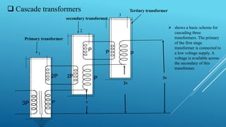
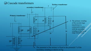
Shantilal Shah Engineering College
TOPIC : GENERATION HIGH A.C VOLTAGE
BY CASCADED TRANSFORMERS
Branch : Electrical
Sem : 6th
Prepared By :
NO. NAME ENROLLMENT NO
1 RATHOD MADHAV 130430109044
2 SINGH SUDHIR 130430109052
3 PATEL BHAVIN 130430109039
4 DABHI SAMIR 130430109011
5 PANDYA NANDISH 130430109034
6 MANDLIYA VALAYAJ 130430109030
CONTENT
Introduction
Testing transformers
Cascade transformers
Application
Introduction
Most of the present day transmission and distribution networks are operating on a.c.
voltages and hence most of the testing equipment relate to high a.c. voltages. Even
though most of the equipment on the system are 3-phase systems, a single phase
transformer operating at power frequency is the most common from of HVAC
testing equipment.
 Test transformers normally used for the purpose have low power rating but high
voltage ratings. These transformers are mainly used for short time tests on high
voltage equipment. The currents required for these tests on various equipment are
given below:
 Insulators, C.B., bushings, Instrumentn transformers = 0.1– 0.5 A
 Power transformers, h.v. capacitors. = 0.5–1 A
 Cables = 1 A and above
Testing transformers
 High voltage power frequency test transformers are required to produce single phase
very high voltage.
 Their continuous current ratings are very low, usually = 1A . Even 1A is a very high
current rating. This is because a HV test transformer has to supply only the capacitive
charging current to the capacitance formed by the dielectric of the test object.
 Howere the voltage rating requirements are high, the test transformers are required to
be produced with very high insulation level.
 This increases the size of the test sets tremendously. Hence, single units of test
transformers are produced maximum upto 700k.
 ultra-high-voltage test:
AC products : 1000kV transformer and shunt reactor with large power.
Other special tests and researching tests In order to fulfill tests mentioned above, the
testing shop equipped with main facilities as following:
Impulse voltage generator : 4800kV/720kJ
AC testing transformer : 630MVA/1700kV
Capacitive divider : 500pF/1500kV
Transformer power loss measurement system : 200kV/4000A TMS580
The ultra-high-voltage test laboratory can carry out not only present products test but
also larger rated power and higher voltage level products test in the future.
 Future TBEA India Factory Testing Hall
 SOME PICTURE OF TESTING TRANSFORMERS
 Cascade transformers
3v
2v
v
------------------------------------
-------
------------------------------------
-------
----------------
----------------
------------------------------------
-------
------------------------------------
-------
----------------
----------------
------------------------------------
-------
------------------------------------
-------
----------------
----------------
1
2
3
Primary transformer
secondary transformer
Tertiary transformer
 shows a basic scheme for
cascading three
transformers. The primary
of the first stage
transformer is connected to
a low voltage supply. A
voltage is available across
the secondary of this
transformer.
 Cascade transformers
3v
2v
v
------------------------------------
-------
------------------------------------
-------
----------------
----------------
------------------------------------
-------
------------------------------------
-------
----------------
----------------
------------------------------------
-------
------------------------------------
-------
----------------
----------------
1
2
3
Primary transformer
secondary transformer
 The tertiary winding
(excitation winding) of
first stage has the same
number of turns as the
primary winding, and
feeds the primary of the
second stage transformer.
 The potential of the tertiary
is fixed to the potential V
of the secondary winding
as shown in Fig.
 Cascade transformers
3v
2v
v
------------------------------------
-------
------------------------------------
-------
----------------
----------------
------------------------------------
-------
------------------------------------
-------
----------------
----------------
------------------------------------
-------
------------------------------------
-------
----------------
----------------
1
2
3
Primary transformer
secondary transformer
Tertiary transformer
 The potential of the tertiary is fixed to the potential V of the
secondary winding as shown in Fig.
 The primary winding
of the second stage
transformer is
connected in series
with the secondary
winding of the secon
stage transformer.
 Cascade transformers
 The secondary
winding of the second
stage transformer is
connected in series
with the secondary
winding of the first
stage transformer, so
that a voltage of 2V is
available between the
ground and the
terminal of secondary
of the second stage
transformer.
3v
2v
v
------------------------------------
-------
------------------------------------
-------
----------------
----------------
------------------------------------
-------
------------------------------------
-------
----------------
----------------
------------------------------------
-------
------------------------------------
-------
----------------
----------------
1
2
3
Primary transformer
secondary transformer
Tertiary transformer
 Cascade transformers
3v
2v
v
------------------------------------
-------
------------------------------------
-------
----------------
----------------
------------------------------------
-------
------------------------------------
-------
----------------
----------------
------------------------------------
-------
------------------------------------
-------
----------------
----------------
1
2
3
Primary transformer
secondary transformer
Tertiary transformer
 the stage-III transformer is
connected in series with the
second stage transformer. With
this the output voltage
between ground and the third
stage transformer, secondary is
3V.
 Cascade transformers
 It is to be noted that the
individual stages except
the upper most must
have three winding
transformers. The upper
most, however, will be a
two winding transformer.
 shows metal tank
construction of
transformers and the
secondary winding is not
divided. Here the low
voltage terminal of the
secondary winding is
connected to the tank.
 Cascade transformers
3v
2v
v
------------------------------------
-------
------------------------------------
-------
----------------
----------------
------------------------------------
-------
------------------------------------
-------
----------------
----------------
------------------------------------
-------
------------------------------------
-------
----------------
----------------
1
2
3
Primary transformer
secondary transformer
Tertiary transformer
 The tank of stage-I
transformer is earthed. The
tanks of stage-II and stage-
III transformers have
potentials of V and 2V,
respectively above earth
and, therefore, these must
be insulated from the earth
with suitable solid
insulation. Through H.T.
bushings, the leads from the
tertiary winding and the h.v.
winding are brought out to
be connected to the next
stage transformer. The tank of stage-I transformer is earthed.
 Cascade transformers
Voltage Control in HV Transformers:
The same voltage is not required for all the tests. For some tests like, breakdown voltage
test, variable voltage supply should be available.
 To vary the output voltage of HV transformers or of a cascaded set of transformers, the
input voltage has to be changed.
 The common method employed for achieving variable voltage is to connect an induction
regulator or a variac on low voltage side.
 Cascade transformers
 Disadvantages :
1) Expensive and requires more space.
 Advantages:
1) Natural cooling is sufficient.
2) The transformers are light and compact.
3) Transportation and assembly is easy.
4) The construction is identical for isolating transformer and the hv cascade unit .
Application
 Cascaded transformer 2 *800 kv (Total rating 1600 kv, 9600 kva) upto.
 Dielectric test under dry and wet condition and pollution test.
 Energizing the experimental transmission line.
 Oscillatory surge (switching ) upto 2000 kv .
(High voltage cascade transformer installation close to Russian city of istra.)
THANKFUL TO YOU …
Questions //?

High voltage