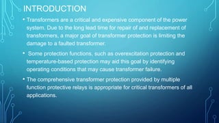
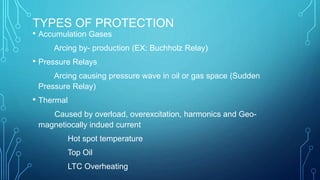
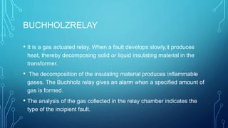
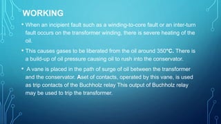
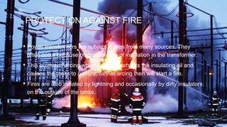
This document discusses transformer protection. Transformers are critical and expensive components that require protection to limit damage from faults. Protection methods include Buchholz relays, which detect gases from arcing; pressure relays, which detect pressure waves from arcing; and thermal relays, which monitor hot spot temperatures. Protection aims to quickly isolate transformers under abnormal conditions like faults, overloads, or overvoltages to prevent failures and simplify repairs.
This PPT explains about the circuit breaker, and its types. Then about the need and purpose of the circuit breaker. And finally the testing and types of testing of circuit breakers.
How is power transformer protected??? This provides a basic understanding of power transformer. Furthermore, the protective relay application on power transformer is included.
Unit I: Introduction to Protection System:
Introduction to protection system and its elements, functions of protective relaying, protective zones, primary and backup protection, desirable qualities of protective relaying, basic terminology.
Relays:
Electromagnetic, attracted and induction type relays, thermal relay, gas actuated relay, design considerations of electromagnetic relay.
Unit-II: Relay Application and Characteristics:
Amplitude and phase comparators, over current relays, directional relays, distance relays, differential relay.
Static Relays: Comparison with electromagnetic relay, classification and their description, over current relays, directional relay, distance relays, differential relay.
Unit-III Protection of Transmission Line:
Over current protection, distance protection, pilot wire protection, carrier current protection, protection of bus, auto re-closing,
Unit-IV: Circuit Breaking:
Properties of arc, arc extinction theories, re-striking voltage transient, current chopping, resistance switching, capacitive current interruption, short line interruption, circuit breaker ratings.
Testing Of Circuit Breaker: Classification, testing station and equipments, testing procedure, direct and indirect testing.
Unit-V Apparatus Protection:
Protection of Transformer, generator and motor.
Circuit Breaker: Operating modes, selection of circuit breakers, constructional features and operation of Bulk Oil, Minimum Oil, Air Blast, SF6, Vacuum and d. c. circuit breakers.
Why do Transformers Fail?
�The electrical windings and the magnetic core in a transformer are subject to a number of different forces during operation, for example:
�Expansion and contraction due to thermal cycling
�Vibration
�Local heating due to magnetic flux
�Impact forces due to through-fault current
�Excessive heating due to overloading or inadequate cooling
In electrical engineering, a protective relay is a relay device designed to trip a circuit breaker when a fault is detected. The theory and application of these protective devices is an important part of the education of a power engineer who specializes in power system protection.
This presentation provides information about different types of protective relaying system.
Equipment and Stability Constraints : System OperationRidwanul Hoque
There are two types of constraints which limit the capability of a power system: If the overloading exceeds limits, the equipment is tripped out by protection systems. b) Stability Constraints: A power system may not be able to cater to power flows beyond a certain point due to stability constraints.
study of lightning arrester ' working principal and working of lighning and construction of lightning arrester. and at the end what are the types of lightning arrester how these types are different from each other and what is their working principal and which is used mostly on 500kva substation.
Welcome to WIPAC Monthly the magazine brought to you by the LinkedIn Group Water Industry Process Automation & Control.
In this month's edition, along with this month's industry news to celebrate the 13 years since the group was created we have articles including
A case study of the used of Advanced Process Control at the Wastewater Treatment works at Lleida in Spain
A look back on an article on smart wastewater networks in order to see how the industry has measured up in the interim around the adoption of Digital Transformation in the Water Industry.
Cosmetic shop management system project report.pdfKamal Acharya
Buying new cosmetic products is difficult. It can even be scary for those who have sensitive skin and are prone to skin trouble. The information needed to alleviate this problem is on the back of each product, but it's thought to interpret those ingredient lists unless you have a background in chemistry.
Instead of buying and hoping for the best, we can use data science to help us predict which products may be good fits for us. It includes various function programs to do the above mentioned tasks.
Data file handling has been effectively used in the program.
The automated cosmetic shop management system should deal with the automation of general workflow and administration process of the shop. The main processes of the system focus on customer's request where the system is able to search the most appropriate products and deliver it to the customers. It should help the employees to quickly identify the list of cosmetic product that have reached the minimum quantity and also keep a track of expired date for each cosmetic product. It should help the employees to find the rack number in which the product is placed.It is also Faster and more efficient way.
CFD Simulation of By-pass Flow in a HRSG module by R&R Consult.pptxR&R Consult
CFD analysis is incredibly effective at solving mysteries and improving the performance of complex systems!
Here's a great example: At a large natural gas-fired power plant, where they use waste heat to generate steam and energy, they were puzzled that their boiler wasn't producing as much steam as expected.
R&R and Tetra Engineering Group Inc. were asked to solve the issue with reduced steam production.
An inspection had shown that a significant amount of hot flue gas was bypassing the boiler tubes, where the heat was supposed to be transferred.
R&R Consult conducted a CFD analysis, which revealed that 6.3% of the flue gas was bypassing the boiler tubes without transferring heat. The analysis also showed that the flue gas was instead being directed along the sides of the boiler and between the modules that were supposed to capture the heat. This was the cause of the reduced performance.
Based on our results, Tetra Engineering installed covering plates to reduce the bypass flow. This improved the boiler's performance and increased electricity production.
It is always satisfying when we can help solve complex challenges like this. Do your systems also need a check-up or optimization? Give us a call!
Work done in cooperation with James Malloy and David Moelling from Tetra Engineering.
More examples of our work https://www.r-r-consult.dk/en/cases-en/
Hierarchical Digital Twin of a Naval Power SystemKerry Sado
A hierarchical digital twin of a Naval DC power system has been developed and experimentally verified. Similar to other state-of-the-art digital twins, this technology creates a digital replica of the physical system executed in real-time or faster, which can modify hardware controls. However, its advantage stems from distributing computational efforts by utilizing a hierarchical structure composed of lower-level digital twin blocks and a higher-level system digital twin. Each digital twin block is associated with a physical subsystem of the hardware and communicates with a singular system digital twin, which creates a system-level response. By extracting information from each level of the hierarchy, power system controls of the hardware were reconfigured autonomously. This hierarchical digital twin development offers several advantages over other digital twins, particularly in the field of naval power systems. The hierarchical structure allows for greater computational efficiency and scalability while the ability to autonomously reconfigure hardware controls offers increased flexibility and responsiveness. The hierarchical decomposition and models utilized were well aligned with the physical twin, as indicated by the maximum deviations between the developed digital twin hierarchy and the hardware.
Student information management system project report ii.pdfKamal Acharya
Our project explains about the student management. This project mainly explains the various actions related to student details. This project shows some ease in adding, editing and deleting the student details. It also provides a less time consuming process for viewing, adding, editing and deleting the marks of the students.
Immunizing Image Classifiers Against Localized Adversary Attacksgerogepatton
This paper addresses the vulnerability of deep learning models, particularly convolutional neural networks
(CNN)s, to adversarial attacks and presents a proactive training technique designed to counter them. We
introduce a novel volumization algorithm, which transforms 2D images into 3D volumetric representations.
When combined with 3D convolution and deep curriculum learning optimization (CLO), itsignificantly improves
the immunity of models against localized universal attacks by up to 40%. We evaluate our proposed approach
using contemporary CNN architectures and the modified Canadian Institute for Advanced Research (CIFAR-10
and CIFAR-100) and ImageNet Large Scale Visual Recognition Challenge (ILSVRC12) datasets, showcasing
accuracy improvements over previous techniques. The results indicate that the combination of the volumetric
input and curriculum learning holds significant promise for mitigating adversarial attacks without necessitating
adversary training.
3. INTRODUCTION
• Transformers are a critical and expensive component of the power
system. Due to the long lead time for repair of and replacement of
transformers, a major goal of transformer protection is limiting the
damage to a faulted transformer.
• Some protection functions, such as overexcitation protection and
temperature-based protection may aid this goal by identifying
operating conditions that may cause transformer failure.
• The comprehensive transformer protection provided by multiple
function protective relays is appropriate for critical transformers of all
applications.
4. • Induction Law
• The transformer is based on two principles:
• 1. An electric current can produce a magnetic field.
• 2. A changing magnetic field within a coil of wire induces a voltage
across the ends of the coil (electromagnetic induction).
5. TRANSFORMER PROTECTION OVERVIEW
• The type of protection for the transformers varies depending on the
application and the importance of the transformer.
• Transformers are protected primarily against faults and overloads. The
type of protection used should minimize the time of disconnection for
faults within the transformer and to reduce the risk of catastrophic
failure to simplify eventual repair.
• Any extended operation of the transformer under abnormal condition
such as faults or overloads compromises the life of the transformer,
which means adequate protection should be provided for quicker
isolation of the transformer under such conditions
6. TRANSFORMER FAILURES
• winding failures due to short circuits (turn-turn faults, phase-phase
faults, phase-ground, open winding).
• core faults (core insulation failure, shorted laminations).
• terminal failures (open leads, loose connections, short circuits).
• on-load tap changer failures (mechanical, electrical, short circuit,
overheating).
• abnormal operating conditions (overfluxing, overloading, overvoltage).
• external faults.
7. CONDITIONS
Internal.
• Winding Phase-Phase, Phase-
Ground faults.
• Winding inter-turn faults.
• Core insulation failure, shorted
laminations.
• Tank faults.
• Over fluxing.
External
• Overloads .
• Overvoltage .
• Over fluxing .
• External system short circuits.
8. TRANSFORMER PROTECTION REVIEW
• Internal Short Circuit
- Phase Faults
- Ground Faults
• System Short Circuits (Back up Protection)
- Buses and Lines
* Phase Faults
* Ground Faults
• Abnormal Condition
• Open Circuit
• Over Excitation
• Abnormal Frequency
• Abnormal Voltage
• Breaker Failure
• Overload
• Geo-magnetically induced current (GIC)
9. TYPES OF PROTECTION
• Accumulation Gases
Arcing by- production (EX: Buchholz Relay)
• Pressure Relays
Arcing causing pressure wave in oil or gas space (Sudden
Pressure Relay)
• Thermal
Caused by overload, overexcitation, harmonics and Geo-
magnetiocally indued current
Hot spot temperature
Top Oil
LTC Overheating
10. BUCHHOLZRELAY
• It is a gas actuated relay. When a fault develops slowly,it produces
heat, thereby decomposing solid or liquid insulating material in the
transformer.
• The decomposition of the insulating material produces inflammable
gases. The Buchholz relay gives an alarm when a specified amount of
gas is formed.
• The analysis of the gas collected in the relay chamber indicates the
type of the incipient fault.
11.
12. WORKING
• When an incipient fault such as a winding-to-core fault or an inter-turn
fault occurs on the transformer winding, there is severe heating of the
oil.
• This causes gases to be liberated from the oil around 350°C. There is
a build-up of oil pressure causing oil to rush into the conservator.
• A vane is placed in the path of surge of oil between the transformer
and the conservator. Aset of contacts, operated by this vane, is used
as trip contacts of the Buchholz relay This output of Buchholz relay
may be used to trip the transformer.
13. PROTECTION AGAINST FIRE
• Power transformers are subject to fires from many sources. They
often occur because of deterioration of insulation in the transformer.
• This produces arcing which in turn overheats the insulating oil and
causes the tanks to rupture; further arcing then will start a fire.
• Fires are also initiated by lightning and occasionally by dirty insulators
on the outside of the tanks.
14.
15. PROTECTION AGAINST LIGHTNING
• Lightning overvoltage surges originate from atmospheric discharges
and they can reach their peak within a few microseconds and
subsequently decay very rapidly.
• The surge voltage can reach up to 10 times the rated transformer
voltage and they pose the greatest threat to transformers on the
distribution networks.
• The charge from the surge produces both short duration high current
impulse and long duration continuing current impulse which affects the
transformer insulation system.
16.
17. CONCLUSION.
• The protective equipment discussed is engineered to limit the damage
and system disturbance caused by faults which can occur in a
transformer.
• The choice of protective equipment depends on the size and the
connection of a transformer, voltage level, power system grounding
and the protective relays of the power network.
• The power companies also have different opinions about the extent
and choice of pr:otective equipment for a transformer.
• No general recommendations can therefore be made.