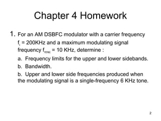
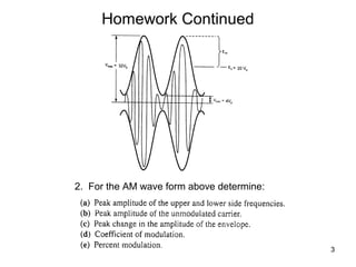
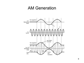
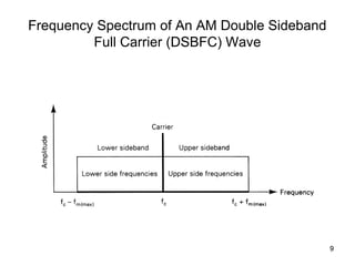
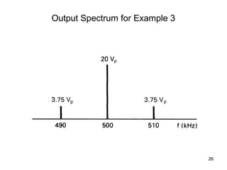
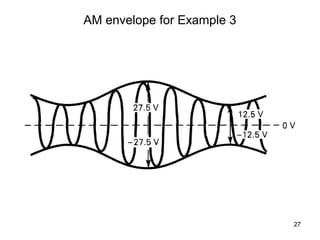
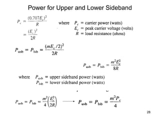
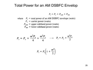
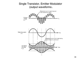
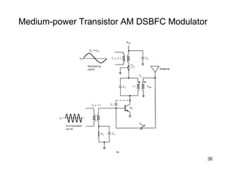
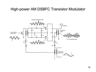
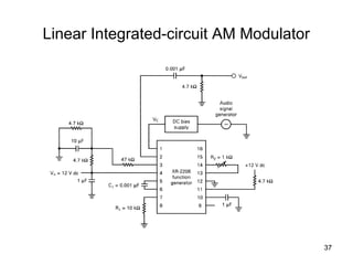
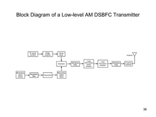
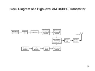
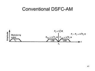
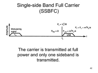
This document discusses amplitude modulation (AM) and covers topics like:
1. Generation of AM signals using double sideband full carrier (DSBFC) modulation.
2. Calculating sideband frequencies and bandwidth for different modulation scenarios.
3. Examining the voltage spectrum and time-domain representation of AM signals.
4. Looking at different AM transmitter and receiver circuit designs including single sideband techniques.
The Presentation includes Basics of Non - Uniform Quantization, Companding and different Pulse Code Modulation Techniques. Comparison of Various PCM techniques is done considering various Parameters in Communication Systems.
RF Carrier oscillator
To generate the carrier signal.
Usually a crystal-controlled oscillator is used.
Buffer amplifier
Low gain, high input impedance linear amplifier.
To isolate the oscillator from the high power amplifiers.
Modulator : can use either emitter collector modulation
Intermediate and final power amplifiers (pull-push modulators)
Required with low-level transmitters to maintain symmetry in the AM envelope
Coupling network
Matches output impedance of the final amplifier to the transmission line/antenn
Applications are in low-power, low-capacity systems : wireless intercoms, remote control units, pagers and short-range walkie-talkie
Modulating signal is processed similarly as in low-level transmitter except for the addition of power amplifier
Power amplifier
To provide higher power modulating signal necessary to achieve 100% modulation (carrier power is maximum at the high-level modulation point).
Same circuit as low-level transmitter for carrier oscillator, buffer and driver but with addition of power amplifier
Details: https://electronicsembeddedworld.blogspot.com/2018/06/performance-management-mcq.html
FM demodulation involves changing the frequency variations in a signal into amplitude variations at baseband, e.g. audio. There are several techniques and circuits that can be used each with its own advantages and disadvantages.
In any radio that is designed to receive frequency modulated signals there is some form of FM demodulator or detector. This circuit takes in frequency modulated RF signals and takes the modulation from the signal to output only the modulation that had been applied at the transmitter.
There are several types of FM detector / demodulator that can be used. Some types were more popular in the days when radios were made from discrete devices, but nowadays the PLL based detector and quadrature / coincidence detectors are the most widely used as they lend themselves to being incorporated into integrated circuits very easily...
Introduction to Angle Modulation, Types of Angle Modulation, Frequency Modulation and Phase Modulation Introduction, Generation of FM, Detection of FM, Frequency stereo Multiplexing, Applications, Difference between FM and PM.
Sampling is a Simple method to convert analog signal into discrete Signal by using any one of its three methods
if the sampling frequency is twice or greater than twice then sampled signal can be convert back into analog signal easily......
This presentation covers noise performance of Continuous wave modulation systems; It explains modelling of white noise , noise figure of DSB-SC, SSB, AM, FM system
This was my first attempt in the field of Embedded Electronics, so kindly have a look at my brief presentation that I have made about my work and experience in this field for the very first time.
SCHULTZ ENTERTRAINING este un program dinamic, interesant și original, adresat adolescenţilor cu vârste cuprinse între 14 şi 18 ani.
SCHULTZ ENTERTRAINING te scoate din mulțime și te învață lucruri practice și utile, într-un cadrul non-formal, fără profi și fără catalog.
SCHULTZ ENTERTRAINING înseamnă un cocktail de fun și knowledge, înseamnă un mixaj de veselie și de seriozitate care îţi aduce în final dezvoltare personală și însuşirea de abilități practice.
SCHULTZ ENTERTRAINING înseamnă traininguri de 2 zile care transformă învățarea într-un proces distractiv și facilitează întâlnirea dintre liceeni și experții noştri, într-un cadru relaxat de sharing experience și transfer of knowledge.
SCHULTZ ENTERTRAINING te provoacă să experimentezi învățarea fără școală și fără profi!
the modulation of a wave by varying its amplitude, used especially as a means of broadcasting an audio signal by combining it with a radio carrier wave.
Water scarcity is the lack of fresh water resources to meet the standard water demand. There are two type of water scarcity. One is physical. The other is economic water scarcity.
Welcome to WIPAC Monthly the magazine brought to you by the LinkedIn Group Water Industry Process Automation & Control.
In this month's edition, along with this month's industry news to celebrate the 13 years since the group was created we have articles including
A case study of the used of Advanced Process Control at the Wastewater Treatment works at Lleida in Spain
A look back on an article on smart wastewater networks in order to see how the industry has measured up in the interim around the adoption of Digital Transformation in the Water Industry.
About
Indigenized remote control interface card suitable for MAFI system CCR equipment. Compatible for IDM8000 CCR. Backplane mounted serial and TCP/Ethernet communication module for CCR remote access. IDM 8000 CCR remote control on serial and TCP protocol.
• Remote control: Parallel or serial interface.
• Compatible with MAFI CCR system.
• Compatible with IDM8000 CCR.
• Compatible with Backplane mount serial communication.
• Compatible with commercial and Defence aviation CCR system.
• Remote control system for accessing CCR and allied system over serial or TCP.
• Indigenized local Support/presence in India.
• Easy in configuration using DIP switches.
Technical Specifications
Indigenized remote control interface card suitable for MAFI system CCR equipment. Compatible for IDM8000 CCR. Backplane mounted serial and TCP/Ethernet communication module for CCR remote access. IDM 8000 CCR remote control on serial and TCP protocol.
Key Features
Indigenized remote control interface card suitable for MAFI system CCR equipment. Compatible for IDM8000 CCR. Backplane mounted serial and TCP/Ethernet communication module for CCR remote access. IDM 8000 CCR remote control on serial and TCP protocol.
• Remote control: Parallel or serial interface
• Compatible with MAFI CCR system
• Copatiable with IDM8000 CCR
• Compatible with Backplane mount serial communication.
• Compatible with commercial and Defence aviation CCR system.
• Remote control system for accessing CCR and allied system over serial or TCP.
• Indigenized local Support/presence in India.
Application
• Remote control: Parallel or serial interface.
• Compatible with MAFI CCR system.
• Compatible with IDM8000 CCR.
• Compatible with Backplane mount serial communication.
• Compatible with commercial and Defence aviation CCR system.
• Remote control system for accessing CCR and allied system over serial or TCP.
• Indigenized local Support/presence in India.
• Easy in configuration using DIP switches.
Hierarchical Digital Twin of a Naval Power SystemKerry Sado
A hierarchical digital twin of a Naval DC power system has been developed and experimentally verified. Similar to other state-of-the-art digital twins, this technology creates a digital replica of the physical system executed in real-time or faster, which can modify hardware controls. However, its advantage stems from distributing computational efforts by utilizing a hierarchical structure composed of lower-level digital twin blocks and a higher-level system digital twin. Each digital twin block is associated with a physical subsystem of the hardware and communicates with a singular system digital twin, which creates a system-level response. By extracting information from each level of the hierarchy, power system controls of the hardware were reconfigured autonomously. This hierarchical digital twin development offers several advantages over other digital twins, particularly in the field of naval power systems. The hierarchical structure allows for greater computational efficiency and scalability while the ability to autonomously reconfigure hardware controls offers increased flexibility and responsiveness. The hierarchical decomposition and models utilized were well aligned with the physical twin, as indicated by the maximum deviations between the developed digital twin hierarchy and the hardware.
CFD Simulation of By-pass Flow in a HRSG module by R&R Consult.pptxR&R Consult
CFD analysis is incredibly effective at solving mysteries and improving the performance of complex systems!
Here's a great example: At a large natural gas-fired power plant, where they use waste heat to generate steam and energy, they were puzzled that their boiler wasn't producing as much steam as expected.
R&R and Tetra Engineering Group Inc. were asked to solve the issue with reduced steam production.
An inspection had shown that a significant amount of hot flue gas was bypassing the boiler tubes, where the heat was supposed to be transferred.
R&R Consult conducted a CFD analysis, which revealed that 6.3% of the flue gas was bypassing the boiler tubes without transferring heat. The analysis also showed that the flue gas was instead being directed along the sides of the boiler and between the modules that were supposed to capture the heat. This was the cause of the reduced performance.
Based on our results, Tetra Engineering installed covering plates to reduce the bypass flow. This improved the boiler's performance and increased electricity production.
It is always satisfying when we can help solve complex challenges like this. Do your systems also need a check-up or optimization? Give us a call!
Work done in cooperation with James Malloy and David Moelling from Tetra Engineering.
More examples of our work https://www.r-r-consult.dk/en/cases-en/
NO1 Uk best vashikaran specialist in delhi vashikaran baba near me online vas...Amil Baba Dawood bangali
Contact with Dawood Bhai Just call on +92322-6382012 and we'll help you. We'll solve all your problems within 12 to 24 hours and with 101% guarantee and with astrology systematic. If you want to take any personal or professional advice then also you can call us on +92322-6382012 , ONLINE LOVE PROBLEM & Other all types of Daily Life Problem's.Then CALL or WHATSAPP us on +92322-6382012 and Get all these problems solutions here by Amil Baba DAWOOD BANGALI
#vashikaranspecialist #astrologer #palmistry #amliyaat #taweez #manpasandshadi #horoscope #spiritual #lovelife #lovespell #marriagespell#aamilbabainpakistan #amilbabainkarachi #powerfullblackmagicspell #kalajadumantarspecialist #realamilbaba #AmilbabainPakistan #astrologerincanada #astrologerindubai #lovespellsmaster #kalajaduspecialist #lovespellsthatwork #aamilbabainlahore#blackmagicformarriage #aamilbaba #kalajadu #kalailam #taweez #wazifaexpert #jadumantar #vashikaranspecialist #astrologer #palmistry #amliyaat #taweez #manpasandshadi #horoscope #spiritual #lovelife #lovespell #marriagespell#aamilbabainpakistan #amilbabainkarachi #powerfullblackmagicspell #kalajadumantarspecialist #realamilbaba #AmilbabainPakistan #astrologerincanada #astrologerindubai #lovespellsmaster #kalajaduspecialist #lovespellsthatwork #aamilbabainlahore #blackmagicforlove #blackmagicformarriage #aamilbaba #kalajadu #kalailam #taweez #wazifaexpert #jadumantar #vashikaranspecialist #astrologer #palmistry #amliyaat #taweez #manpasandshadi #horoscope #spiritual #lovelife #lovespell #marriagespell#aamilbabainpakistan #amilbabainkarachi #powerfullblackmagicspell #kalajadumantarspecialist #realamilbaba #AmilbabainPakistan #astrologerincanada #astrologerindubai #lovespellsmaster #kalajaduspecialist #lovespellsthatwork #aamilbabainlahore #Amilbabainuk #amilbabainspain #amilbabaindubai #Amilbabainnorway #amilbabainkrachi #amilbabainlahore #amilbabaingujranwalan #amilbabainislamabad
2. 2
Chapter 4 Homework
1. For an AM DSBFC modulator with a carrier frequency
fc = 200KHz and a maximum modulating signal
frequency fm(max) = 10 KHz, determine :
a. Frequency limits for the upper and lower sidebands.
b. Bandwidth.
b. Upper and lower side frequencies produced when
the modulating signal is a single-frequency 6 KHz tone.
5. 5
Homework Continued
4. Repeat steps (a) through (d) in Example
4 in these lecture slides for a modulation
coefficient of 0.5.
5. For an AM DSBFC wave with a peak
unmodulated carrier voltage Vc = 20 Vp, a
load resistance RL = 20 W, and a
modulation coefficient m = 0.8,
determine the power of the modulated
wave
6. Homework Continued
6.Determine the noise improvement for a
receiver with an RF bandwidth equal to
100 KHz and an IF bandwidth equal to 20
KHz.
6
10. 10
Example 1
For an AM DSBFC modulator with a carrier frequency
fc = 100KHz and a maximum modulating signal
frequency fm(max) = 5 KHz, determine :
a. Frequency limits for the upper and lower sidebands.
b. Bandwidth.
c. Upper and lower side frequencies produced when the
modulating signal is a single-frequency 3 KHz tone.
12. 12
Example 1 d. The Output Spectrum
For An AM DSBFC Wave
13. 13
Phasor addition in an AM DSBFC envelope
• For a single-frequency modulating signal, am AM
envelop is produced from the vector addition of the
carrier and upper and lower side frequencies.
Phasors of the carrier,
• The upper and lower frequencies combine and
produce a resultant component that combines with
the carrier component.
• Phasors for the carrier, upper and lower
frequencies all rotate in the counterclockwise
direction.
• The upper sideband frequency rotates faster than
the carrier. (wusf > wc)
• The lower sideband frequency rotes slower than
the carrier. (wusf < wc)
16. If the modulating signal is pure, single frequency sine wave and the modulation
process is symmetrical, the % modulation can be derived as follows:
16
17. 17
Peak Amplitudes of Upper and Lower Sidebands
The peak change in amplitude of the output wave
(Em) is equal to the sum of the voltages from the
upper and lower sideband frequencies. Therefore,
18. Percent Modulation of An AM DSBFC Envelope
(a) modulating signal; (b) unmodulated carrier; (c) 50% modulated wave;
18
(d) 100% modulated wave
19. 19
Example 2
For the AM wave form above determine:
57. 57
Simplified Block Diagram of an AM Receiver
• Receiver front end = RF section
– Detecting the signal
– Band-limiting the signal
– Amplifying the Band-limited signal
• Mixer/converter
– Down converts the RF signal to an IF signal
• Intermediate frequency (IF) signal
– Amplification
– Selectivity
• Ability of a receiver to accept assigned frequency
• Ability of a receiver to reject other frequencies
• AM detector demodulates the IF signal to the original signal
• Audio section amplifies the recovered signal.
60. 60
Bandwidth Improvement (BI)
• Noise reduction ratio
• BI = BRF / BIF
• Noise figure improvement
• NFIMP = 10 log BI
• Determine the noise improvement for a receiver with an
RF bandwidth equal to 200 KHz and an IF bandwidth
equal to 10 KHz.
– BI = 200 KHz / 10 KHZ = 20
– NFImp = 10 log 20 = 13 dB
61. 61
Sensitivity
• Sensitivity: minimum RF signal level that the
receiver can detect at the RF input.
• AM broadcast receivers
– 10 dB signal to noise ratio
– ½ watt (27 dBm) of power at the audio output
– 50 uV Sensitivity
• Microwave receivers
– 40 dB signal to noise ratio
– 5 mw (7 dBm) of power at the output
• Aa
62. 62
Dynamic Range
• Dynamic Range
– Difference in dB between the minimum input level and
the level that will over drive the receiver (produce
distortion).
– Input power range that the receiver is useful.
– 100 dB is about the highest posible.
• Low Dynamic Range
– Causes desensitizing of the RF amplifiers
– Results in sever inter-modulation distortion of weaker
signals
63. 63
Fidelity
• Ability to produce an exact replica of the original signal.
• Forms of distortion
– Amplitude
• Results from non-uniform gain in amplifiers and filters.
• Output signal differs from the original signal
– Frequency: frequencies are in the output that were
not in the orginal signal
– Phase
• Not important for voice transmission
• Devastating for digital transmission