Downloaded 183 times
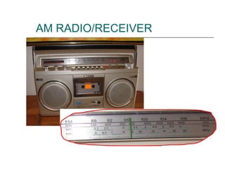
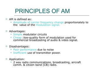
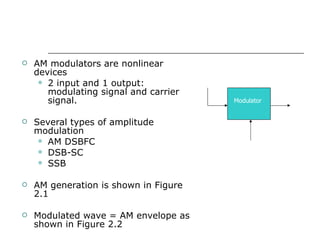

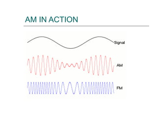
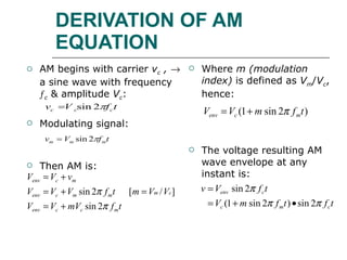
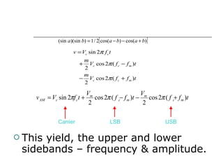

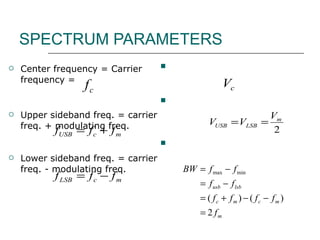
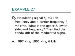
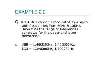

This document discusses amplitude modulation (AM) used in radio broadcasting. It describes the principles of AM including: imposing an information signal onto a carrier wave such that the carrier amplitude varies proportionally to the information signal. This creates sidebands above and below the carrier frequency. The bandwidth of an AM signal is equal to twice the highest modulating frequency. Circuits and examples are provided to illustrate AM modulation and demodulation.


