By
Rajatsoni
MTECHWct
e.no.-140291
What is EMC?
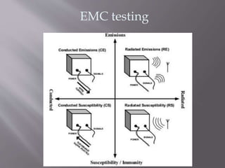
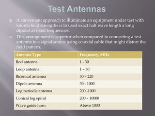
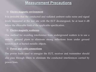
Electromagnetic compatibility (EMC) is the branch of
electrical sciences which studies the unintentional
generation, propagation and reception of electromagnetic
energy with reference to the unwanted effects
(Electromagnetic interference, or EMI) that such energy
may induce.
The goal of EMC is the correct operation, in the same
electromagnetic environment, of different equipment which
use electromagnetic phenomena, and the avoidance of any
interference effects.
• While electromagnetic interference (EMI) is
a phenomenon - the radiation emitted and its effects -
electromagnetic compatibility (EMC) is an equipment
characteristic or property - not to behave unacceptably in
the EMI environment.
• Electromagnetic interference divides into several
categories according to the source and signal
characteristics. But generally
• Types of interference
• Continuous interference
• Pulse or transient interference
EMC testing
• Open-air test sites, or OATS, are the reference sites in
most standards. They are especially useful for
emissions testing of large equipment systems.
• Radiated field susceptibility testing typically involves
a high-powered source of RF or EM pulse energy and
a radiating antenna to direct the energy.
Measurement of Radiated Emissions
Measurement of
Radiated Susceptibility
 A convenient approach to illuminate an equipment under test with
known field strengths is to used exact half wave length a long
dipoles at fixed frequencies.
 This arrangement is superior when compared to connecting a test
antenna to a signal source using co-axial cable that might distort the
field pattern.
Antenna Type Frequency, MHz
Rod antenna 1 - 30
Loop antenna 1 – 30
Biconical antenna 30 – 220
Dipole antenna 30 - 1000
Log periodic antenna 200 -1000
Conical log spiral 200 – 10000
Wave guide horn Above 1000
1) Electro magnetic environment
It is desirable that the conducted and radiated ambient radio noise and signal
levels measured at the test site with the EUT de-energized, be at least 6 dB
below the allowable limit of the applicable specification.
2) Electro magnetic scatterers
One method for avoiding interference from underground scatters is to use a
metallic ground plane to eliminate strong reflections from under ground
sources such as buried metallic objects.
3) Power and cable connections
The power leads used to energize the EUT, receiver and transmitter should
also pass through filters to eliminate the conducted interferences carried by
power lines.
Measurement Precautions
Presentation on emc testing and measurement

Presentation on emc testing and measurement

  • 1.
  • 2.
    What is EMC? Electromagneticcompatibility (EMC) is the branch of electrical sciences which studies the unintentional generation, propagation and reception of electromagnetic energy with reference to the unwanted effects (Electromagnetic interference, or EMI) that such energy may induce. The goal of EMC is the correct operation, in the same electromagnetic environment, of different equipment which use electromagnetic phenomena, and the avoidance of any interference effects.
  • 3.
    • While electromagneticinterference (EMI) is a phenomenon - the radiation emitted and its effects - electromagnetic compatibility (EMC) is an equipment characteristic or property - not to behave unacceptably in the EMI environment. • Electromagnetic interference divides into several categories according to the source and signal characteristics. But generally • Types of interference • Continuous interference • Pulse or transient interference
  • 4.
  • 5.
    • Open-air testsites, or OATS, are the reference sites in most standards. They are especially useful for emissions testing of large equipment systems. • Radiated field susceptibility testing typically involves a high-powered source of RF or EM pulse energy and a radiating antenna to direct the energy.
  • 6.
  • 7.
  • 8.
     A convenientapproach to illuminate an equipment under test with known field strengths is to used exact half wave length a long dipoles at fixed frequencies.  This arrangement is superior when compared to connecting a test antenna to a signal source using co-axial cable that might distort the field pattern. Antenna Type Frequency, MHz Rod antenna 1 - 30 Loop antenna 1 – 30 Biconical antenna 30 – 220 Dipole antenna 30 - 1000 Log periodic antenna 200 -1000 Conical log spiral 200 – 10000 Wave guide horn Above 1000
  • 9.
    1) Electro magneticenvironment It is desirable that the conducted and radiated ambient radio noise and signal levels measured at the test site with the EUT de-energized, be at least 6 dB below the allowable limit of the applicable specification. 2) Electro magnetic scatterers One method for avoiding interference from underground scatters is to use a metallic ground plane to eliminate strong reflections from under ground sources such as buried metallic objects. 3) Power and cable connections The power leads used to energize the EUT, receiver and transmitter should also pass through filters to eliminate the conducted interferences carried by power lines. Measurement Precautions