Downloaded 131 times

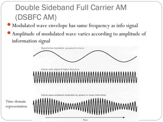
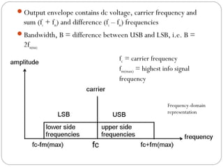

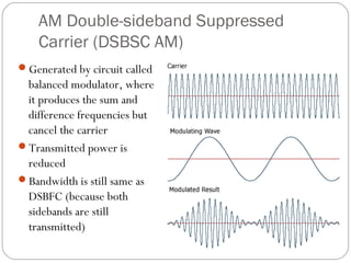


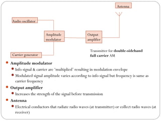


This document discusses linear modulation techniques, specifically amplitude modulation (AM). It describes the main types of AM including double sideband full carrier (DSBFC), double sideband suppressed carrier (DSBSC), and single sideband suppressed carrier (SSBSC). It provides details on how each is generated and transmitted, their advantages and disadvantages, and the basic components and functioning of AM transmitters and receivers.