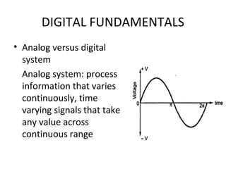
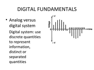
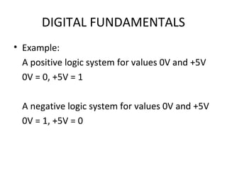
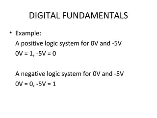
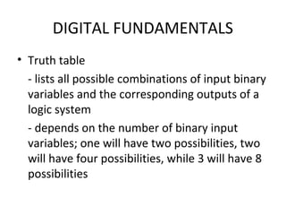
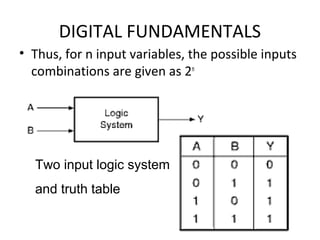
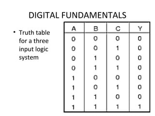
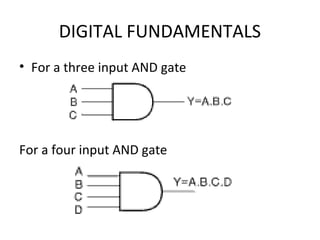
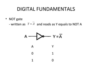
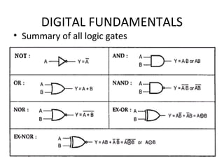
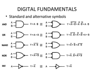
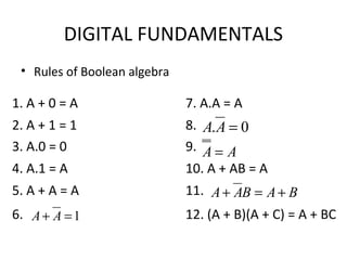
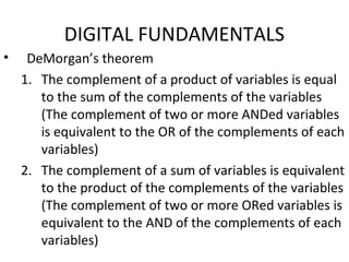
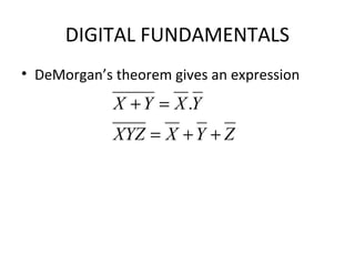
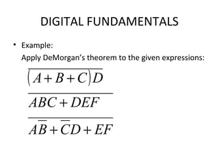
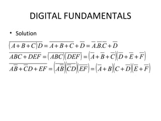
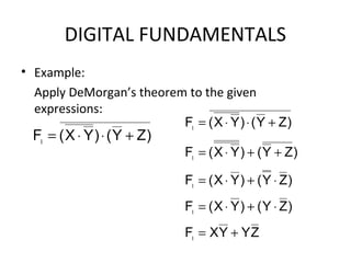
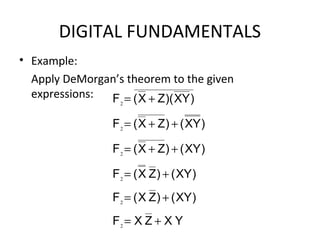
DIGITAL ELECTRONICS
CHAPTER 2
DEE 204
DIGITAL ELECTRONICS
Digital fundamentals
Difference between analog and digital
systems.
Logic levels and families.
Logic values, truth tables and logical
operations.
Boolean algebra.
De Morgan’s Theorem
DIGITAL FUNDAMENTALS
• Analog versus digital
system
Analog system: process
information that varies
continuously, time
varying signals that take
any value across
continuous range
DIGITAL FUNDAMENTALS
• Analog versus
digital system
Digital system: use
discrete quantities
to represent
information,
distinct or
separated
quantities
DIGITAL FUNDAMENTALS
• Advantages of digital system:
– ease of design
– reproducibility of result
– flexibility
– functionality
– programmability
– speed
– economy
DIGITAL FUNDAMENTALS
• Logic levels
Binary logic used in digital system assumes
only TWO values: HIGH or LOW
These two levels or states can represent
two numerals: 1 and 0 of the binary system or
two logic states: TRUE and FALSE of the logic
operations
DIGITAL FUNDAMENTALS
• Logic family
- fundamental approach used to produce
different types of digital integrated circuit
- different logic functions belonging to the
same logic family will have identical
electrical characteristics: supply voltage
range, speed of response, power
dissipation, input and output logic levels,
current sourcing and sinking capability,
etc., making it compatible with each other
DIGITAL FUNDAMENTALS
• Types of logic families:
1. Bipolar – diode logic (DL), resistor
transistor logic (RTL), diode transistor
logic (DTL), transistor transistor logic
(TTL), emitter couple logic (ECL), current
mode logic (CML), integrated injection
logic (IIL or I2
L)
2. MOS – PMOS, NMOS, CMOS
3. Bi-MOS – using both bipolar and MOS
DIGITAL FUNDAMENTALS
• Binary variables have either logic ‘0’ state or
logic ‘1’ state which usually represents two
different voltage or current levels
• It may be a more positive(1) or less positive
(0) value referred as positive logic system
• Or may be the more positive (0) and less
positive (1) referred as negative logic system
DIGITAL FUNDAMENTALS
• Example:
A positive logic system for values 0V and +5V
0V = 0, +5V = 1
A negative logic system for values 0V and +5V
0V = 1, +5V = 0
DIGITAL FUNDAMENTALS
• Example:
A positive logic system for 0V and -5V
0V = 1, -5V = 0
A negative logic system for 0V and -5V
0V = 0, -5V = 1
DIGITAL FUNDAMENTALS
• Truth table
- lists all possible combinations of input binary
variables and the corresponding outputs of a
logic system
- depends on the number of binary input
variables; one will have two possibilities, two
will have four possibilities, while 3 will have 8
possibilities
DIGITAL FUNDAMENTALS
• Thus, for n input variables, the possible inputs
combinations are given as 2n
Two input logic system
and truth table
DIGITAL FUNDAMENTALS
• Truth table
for a three
input logic
system
DIGITAL FUNDAMENTALS
• Logic gates
- most basic building block of any digital
system
- a piece of hardware or an electronic circuit
used to implement basic logic expression
- the three basic logic gates are OR gate, AND
gate and NOT gate
DIGITAL FUNDAMENTALS
• OR gate
- to perform OR operation for two or
more logic variables with two or more
inputs and one output
- written as Y = A + B (Y equals to A OR B)
- output of OR gate is LOW when all inputs
are LOW and HIGH for any other input
combinations
DIGITAL FUNDAMENTALS
• OR gate
For a two input OR gate:
DIGITAL FUNDAMENTALS
• Example:
For an input waveform fed into a OR gate,
sketch the output waveform.
DIGITAL FUNDAMENTALS
• Solution:
The output waveform produced by a OR gate
DIGITAL FUNDAMENTALS
• AND gate
- also with two or more inputs and one output
- the output is HIGH when all inputs are HIGH
and LOW for any other combinations
- the output will become ‘1’ only when all
inputs are ‘1’
- written as Y = A.B (Y equals to A AND B)
DIGITAL FUNDAMENTALS
• AND gate
For a two input AND gate:
DIGITAL FUNDAMENTALS
• For a three input AND gate
For a four input AND gate
DIGITAL FUNDAMENTALS
• NOT gate
- a one input one output logic circuit which
complements the input
- the input is HIGH when the input is LOW and
vice versa
- a logic ‘0’ produces a logic ‘1’
- known as ‘complementing’ or ‘inverting’
circuit
DIGITAL FUNDAMENTALS
• NOT gate
- written as and reads as Y equals to NOT AAY =
A Y
0 1
1 0
DIGITAL FUNDAMENTALS
• Summary of all logic gates
DIGITAL FUNDAMENTALS
• Standard and alternative symbols
DIGITAL FUNDAMENTALS
• Example:
Draw an alternative circuit of the circuit
shown
DIGITAL FUNDAMENTALS
• Solution
DIGITAL FUNDAMENTALS
• Boolean algebra
- used to do manipulation of binary
variables and simplify logic expressions
- is basically the mathematics of logic
- composed of a set of symbols and a set
of rules to manipulate these symbols
DIGITAL FUNDAMENTALS
• Rules of Boolean algebra
1. A + 0 = A 7. A.A = A
2. A + 1 = 1 8.
3. A.0 = 0 9.
4. A.1 = A 10. A + AB = A
5. A + A = A 11.
6. 12. (A + B)(A + C) = A + BC1=+ AA
0. =AA
AA =
BABAA +=+
DIGITAL FUNDAMENTALS
• Boolean algebra
–There are cases when Boolean
algebra is used to simplify a Boolean
expression
–Simplification means fewer gates for
the same function
DIGITAL FUNDAMENTALS
• Example:
Simplify the given expression using Boolean algebra
techniques
( ) ( )CBBCBAAB ++++
DIGITAL FUNDAMENTALS
• Solution:
( ) ( )
ACB
BACAB
BCBACAB
BCBBACABAB
CBBCBAAB
+=
=+
++=
=+
+++=
=+=
++++=
++++
B)B(ABapplying
B)BC(Bapplying
AB)AB(ABandB)(BBapplying
givesequationtheexpanding
DIGITAL FUNDAMENTALS
• DeMorgan’s theorem
1. The complement of a product of variables is equal
to the sum of the complements of the variables
(The complement of two or more ANDed variables
is equivalent to the OR of the complements of each
variables)
2. The complement of a sum of variables is equivalent
to the product of the complements of the variables
(The complement of two or more ORed variables is
equivalent to the AND of the complements of each
variables)
DIGITAL FUNDAMENTALS
• DeMorgan’s theorem gives an expression
ZYXXYZ
YXYX
++=
=+ .
DIGITAL FUNDAMENTALS
• Example:
Apply DeMorgan’s theorem to the given expressions:
( )
EFDCBA
DEFABC
DCBA
++
+
++
DIGITAL FUNDAMENTALS
• Solution
( )
( )( ) ( )( )
( )( )( ) ( )( )( )FEDCBAEFDCBAEFDCBA
FEDCBADEFABCDEFABC
DCBADCBADCBA
+++==++
++++==+
+=+++=++ ..
DIGITAL FUNDAMENTALS
• Example:
Apply DeMorgan’s theorem to the given
expressions:
)ZY()YX(F +⋅⋅=1
ZYYXF
)ZY()YX(F
)ZY()YX(F
)ZY()YX(F
)ZY()YX(F
+=
⋅+⋅=
⋅+⋅=
++⋅=
+⋅⋅=
1
1
1
1
1
DIGITAL FUNDAMENTALS
• Example:
Apply DeMorgan’s theorem to the given
expressions:
YXZXF
)XY()ZX(F
)XY()ZX(F
)XY()ZX(F
)XY()ZX(F
)XY)(ZX(F
+=
+=
+=
++=
++=
+=
2
2
2
2
2
2

Digital design chap 2

  • 1.
  • 2.
    DIGITAL ELECTRONICS Digital fundamentals Differencebetween analog and digital systems. Logic levels and families. Logic values, truth tables and logical operations. Boolean algebra. De Morgan’s Theorem
  • 3.
    DIGITAL FUNDAMENTALS • Analogversus digital system Analog system: process information that varies continuously, time varying signals that take any value across continuous range
  • 4.
    DIGITAL FUNDAMENTALS • Analogversus digital system Digital system: use discrete quantities to represent information, distinct or separated quantities
  • 5.
    DIGITAL FUNDAMENTALS • Advantagesof digital system: – ease of design – reproducibility of result – flexibility – functionality – programmability – speed – economy
  • 6.
    DIGITAL FUNDAMENTALS • Logiclevels Binary logic used in digital system assumes only TWO values: HIGH or LOW These two levels or states can represent two numerals: 1 and 0 of the binary system or two logic states: TRUE and FALSE of the logic operations
  • 7.
    DIGITAL FUNDAMENTALS • Logicfamily - fundamental approach used to produce different types of digital integrated circuit - different logic functions belonging to the same logic family will have identical electrical characteristics: supply voltage range, speed of response, power dissipation, input and output logic levels, current sourcing and sinking capability, etc., making it compatible with each other
  • 8.
    DIGITAL FUNDAMENTALS • Typesof logic families: 1. Bipolar – diode logic (DL), resistor transistor logic (RTL), diode transistor logic (DTL), transistor transistor logic (TTL), emitter couple logic (ECL), current mode logic (CML), integrated injection logic (IIL or I2 L) 2. MOS – PMOS, NMOS, CMOS 3. Bi-MOS – using both bipolar and MOS
  • 9.
    DIGITAL FUNDAMENTALS • Binaryvariables have either logic ‘0’ state or logic ‘1’ state which usually represents two different voltage or current levels • It may be a more positive(1) or less positive (0) value referred as positive logic system • Or may be the more positive (0) and less positive (1) referred as negative logic system
  • 10.
    DIGITAL FUNDAMENTALS • Example: Apositive logic system for values 0V and +5V 0V = 0, +5V = 1 A negative logic system for values 0V and +5V 0V = 1, +5V = 0
  • 11.
    DIGITAL FUNDAMENTALS • Example: Apositive logic system for 0V and -5V 0V = 1, -5V = 0 A negative logic system for 0V and -5V 0V = 0, -5V = 1
  • 12.
    DIGITAL FUNDAMENTALS • Truthtable - lists all possible combinations of input binary variables and the corresponding outputs of a logic system - depends on the number of binary input variables; one will have two possibilities, two will have four possibilities, while 3 will have 8 possibilities
  • 13.
    DIGITAL FUNDAMENTALS • Thus,for n input variables, the possible inputs combinations are given as 2n Two input logic system and truth table
  • 14.
    DIGITAL FUNDAMENTALS • Truthtable for a three input logic system
  • 15.
    DIGITAL FUNDAMENTALS • Logicgates - most basic building block of any digital system - a piece of hardware or an electronic circuit used to implement basic logic expression - the three basic logic gates are OR gate, AND gate and NOT gate
  • 16.
    DIGITAL FUNDAMENTALS • ORgate - to perform OR operation for two or more logic variables with two or more inputs and one output - written as Y = A + B (Y equals to A OR B) - output of OR gate is LOW when all inputs are LOW and HIGH for any other input combinations
  • 17.
    DIGITAL FUNDAMENTALS • ORgate For a two input OR gate:
  • 18.
    DIGITAL FUNDAMENTALS • Example: Foran input waveform fed into a OR gate, sketch the output waveform.
  • 19.
    DIGITAL FUNDAMENTALS • Solution: Theoutput waveform produced by a OR gate
  • 20.
    DIGITAL FUNDAMENTALS • ANDgate - also with two or more inputs and one output - the output is HIGH when all inputs are HIGH and LOW for any other combinations - the output will become ‘1’ only when all inputs are ‘1’ - written as Y = A.B (Y equals to A AND B)
  • 21.
    DIGITAL FUNDAMENTALS • ANDgate For a two input AND gate:
  • 22.
    DIGITAL FUNDAMENTALS • Fora three input AND gate For a four input AND gate
  • 23.
    DIGITAL FUNDAMENTALS • NOTgate - a one input one output logic circuit which complements the input - the input is HIGH when the input is LOW and vice versa - a logic ‘0’ produces a logic ‘1’ - known as ‘complementing’ or ‘inverting’ circuit
  • 24.
    DIGITAL FUNDAMENTALS • NOTgate - written as and reads as Y equals to NOT AAY = A Y 0 1 1 0
  • 25.
  • 26.
    DIGITAL FUNDAMENTALS • Standardand alternative symbols
  • 27.
    DIGITAL FUNDAMENTALS • Example: Drawan alternative circuit of the circuit shown
  • 28.
  • 29.
    DIGITAL FUNDAMENTALS • Booleanalgebra - used to do manipulation of binary variables and simplify logic expressions - is basically the mathematics of logic - composed of a set of symbols and a set of rules to manipulate these symbols
  • 30.
    DIGITAL FUNDAMENTALS • Rulesof Boolean algebra 1. A + 0 = A 7. A.A = A 2. A + 1 = 1 8. 3. A.0 = 0 9. 4. A.1 = A 10. A + AB = A 5. A + A = A 11. 6. 12. (A + B)(A + C) = A + BC1=+ AA 0. =AA AA = BABAA +=+
  • 31.
    DIGITAL FUNDAMENTALS • Booleanalgebra –There are cases when Boolean algebra is used to simplify a Boolean expression –Simplification means fewer gates for the same function
  • 32.
    DIGITAL FUNDAMENTALS • Example: Simplifythe given expression using Boolean algebra techniques ( ) ( )CBBCBAAB ++++
  • 33.
    DIGITAL FUNDAMENTALS • Solution: () ( ) ACB BACAB BCBACAB BCBBACABAB CBBCBAAB += =+ ++= =+ +++= =+= ++++= ++++ B)B(ABapplying B)BC(Bapplying AB)AB(ABandB)(BBapplying givesequationtheexpanding
  • 34.
    DIGITAL FUNDAMENTALS • DeMorgan’stheorem 1. The complement of a product of variables is equal to the sum of the complements of the variables (The complement of two or more ANDed variables is equivalent to the OR of the complements of each variables) 2. The complement of a sum of variables is equivalent to the product of the complements of the variables (The complement of two or more ORed variables is equivalent to the AND of the complements of each variables)
  • 35.
    DIGITAL FUNDAMENTALS • DeMorgan’stheorem gives an expression ZYXXYZ YXYX ++= =+ .
  • 36.
    DIGITAL FUNDAMENTALS • Example: ApplyDeMorgan’s theorem to the given expressions: ( ) EFDCBA DEFABC DCBA ++ + ++
  • 37.
    DIGITAL FUNDAMENTALS • Solution () ( )( ) ( )( ) ( )( )( ) ( )( )( )FEDCBAEFDCBAEFDCBA FEDCBADEFABCDEFABC DCBADCBADCBA +++==++ ++++==+ +=+++=++ ..
  • 38.
    DIGITAL FUNDAMENTALS • Example: ApplyDeMorgan’s theorem to the given expressions: )ZY()YX(F +⋅⋅=1 ZYYXF )ZY()YX(F )ZY()YX(F )ZY()YX(F )ZY()YX(F += ⋅+⋅= ⋅+⋅= ++⋅= +⋅⋅= 1 1 1 1 1
  • 39.
    DIGITAL FUNDAMENTALS • Example: ApplyDeMorgan’s theorem to the given expressions: YXZXF )XY()ZX(F )XY()ZX(F )XY()ZX(F )XY()ZX(F )XY)(ZX(F += += += ++= ++= += 2 2 2 2 2 2