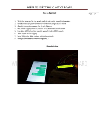
This document describes a wireless electronic notice board that displays notices sent via SMS from a mobile phone. The circuit uses an Arduino microcontroller, GSM module to receive SMS messages, and a 16x2 LCD for display. When an SMS with a notice message is sent, the GSM module receives it and sends it to the Arduino. The Arduino then extracts and displays the notice message on the LCD. This allows notices to be updated and viewed remotely via SMS from any location with cellular network access.
2. WIRELESS ELECTRONIC NOTICE BOARD
Page | 2
Abstract
Notice Boardis primarythinginany institution/organizationorpublicutilityplaceslike bus
stations,railwaystationsandparks,But stickingvariousnoticesday-to-dayisadifficultprocess.A
separate personisrequiredtotake care of thisnoticesdisplay.Thisprojectdealsaboutanadvancedhi -
techwirelessnotice board.
The main objective of the projectistodevelopawireless notice boardthatdisplaysnotices
whena message issentfromthe usersmobile.Whilethe usersendsthe messagefromthe mobile,itis
receivedandretrievedbythe GSMmodemat the displayunit.Itisthensentto the microcontroller
(ATmega328) that furtherdisplaysthe notice sentfromthe usernoto the electronicnotice boardwhich
isequippedwitha16X2 LCD display.
The powersupplyconsistsof a stepdowntransformer230/12V, whichstepsdownthe voltage
to 12V AC. Thisis convertedtoDC usinga Bridge rectifier.The ripplesare removedusingacapacitive
filteranditis thenregulatedto+5V usinga voltage regulator7805 whichisrequiredforthe operationof
the microcontrollerandothercomponents.
3. WIRELESS ELECTRONIC NOTICE BOARD
Page | 3
Introduction
The projectmainlyfocusesontransmissionof textual datathroughairinterface bythe use of GSM
throughserial communication.The datawill be displayedonLCDonlyafterenteringunique passkey
before andafterthe message.Actuallywhathappensis,sendingSMSthroughphone hasbecome very
popularandif we can use thisSMS to control devicesandindisplayingdata,thenitwill be greatuse of
it.It is possible toreceiveordecode the SMSgloballybyusingGSMMODEM from anypart of the world.
So,we can control and displaydataonLCD boardfrom a large distance.
In thisproject,ArduinoUNOisusedforcontrollingthe whole process,GSMmodule (SIM300) to
receive the SMS/message sentfrommobilephone andLCDto displaythe message.We cansendsome
message ornotice like “#welcome brother*”,“#We WelcomesYou*”throughthe SMS. Here we have
useda prefix inthe message stringthatis‘#’.This prefix isusedtoidentifythe startingof the message
or notice.And‘*’ isusedas suffix toindicate the endof the message ornotice.
Whenwe sendSMS from mobile phone toGSMmodule thenGSMreceivesthatSMS andsends
it to Arduino.NowArduinoreadthisSMSandextractmain notice message fromthe receivedstringand
storesinanotherstring. Andthensendsthe extractedmessage to16x2 LCD byusingappropriate
commands.
Here we not onlysendthe data butsendthe data withpass code also.Whichenablesusto preventthe
unauthorizeduse of LCDdisplayboardandonlythe personwhohave pass code can have access to LCD
board . The maincomponentsof the kitinclude MICROCONTROLLER, GSM MODEM. These components
are integratedwiththe LCDDISPLAY BOARD and thusincorporate the wirelessfeatures.The GSM
modemreceivesthe SMS.The AT commandsare seriallytransferredtothe modem, Inreturnthe
modemtransmitsthe storedmessage throughthe COMport.The microcontrollervalidatesthe SMSand
thendisplaysthe message inthe LCDdisplayboard.
The main focusof the thesisisondisplayinginformationtoadedicatedLCDby the any part of world
usingGSM network,whichfacilitate tocontrol anymessage boardgloballyfromanylocation.
4. WIRELESS ELECTRONIC NOTICE BOARD
Page | 4Circuit Principle
Whenwe sendthe message fromthe mobile,GSMmodemwhichisarrangedat the displayunitreceives
the message.Nowthe controllerreadsthe message fromthe GSMmodemanddisplaysinonLCD.
Whenusersendsthe message fromthe mobile,GSMmodemsendsthe below commandseriallyto
indicate thatnewmessage isreceived.
+CMTI: “SM”,3
In the above commandnumber3 indicatesthe locationof the new message.Now youneedtoreadthis
unreadmessage todisplayonLCD. The commandto read the message fromGSMmodemis
at+cmgr=3
Here the number3 indicatesthe locationof the message tobe read.AftergivingthiscommandGSM
module sendthe below commandserially.
+CMGR: “REC UNREAD”,”MD-WAYSMS”,,”13/05/20,15:31:48+34”Physics
In the above command“REC UNREAD” indicatesthatmessage isunreadmessage,“MD-WAYSMS”
indicatessendermobilenumberorname,13/05/20 indicatesthe date,15:31 indicatestime and Physics
isthe contentof the message.
From the above commandwe needtoextractmessage (physics) sentbythe userto displayonnotice
board.
5. WIRELESS ELECTRONIC NOTICE BOARD
Page | 5Circuit Diagram
Circuit diagram of wireless electronic notice board using GSM module
The above circuitconsistsof Arduino UNO controllerboard,GSMmodule and16*2 LCD. LCD is
connectedanditis usedto displaymessage.GSMmodule isconnectedtocontrollerusingjumpers
where Rx of GSM isconnectedtoT x of ArduinoandTX of GSM is connectedtoRx of Arduino
Here LCD is usedin4 bitmode.Meansonly4 data linesare requiredtodisplaythe data.These datalines
are connectedto8, 9, 10 and 11 and control pinsRS,RW, EN pinsare connectedto2, GND and 4
respectively.
GSM module need12vpowersupplyandArduinoandlcdneed5v powersupplyhence tooperate a
circuitwe need2 powersupply.
6. WIRELESS ELECTRONIC NOTICE BOARD
Page | 6Circuit Components
ATmega328
The ArduinoUno isa microcontrollerboardbasedonthe ATmega328. It has 14 digital
input/outputpins(of which6can be usedas PWMoutputs),6 analoginputs,a 16 MHz ceramic
resonator,a USB connection,apowerjack,an ICSPheader,anda resetbutton.Itcontains
everythingneededtosupportthe microcontroller;simplyconnectittoa computerwitha USB
cable or poweritwith an AC-to-
DC adapteror battery to get
started.
Summary
Microcontroller ATmega328
OperatingVoltage 5V
InputVoltage (recommended) 7-12V
InputVoltage (limits) 6-20V
Digital I/OPins 14 (of which6 provide PWMoutput)
AnalogInputPins 6
DC Currentper I/OPin 40 mA
DC Currentfor 3.3V Pin 50 mA
FlashMemory 32 KB (ATmega328) of which0.5 KB usedby bootloader
EEPROM 1 KB (ATmega328)
ClockSpeed 16 MHz
7. WIRELESS ELECTRONIC NOTICE BOARD
Page | 7 16*2 LCD
LCD (LiquidCrystal Display) screenisanelectronicdisplaymoduleandfindawide range of
applications.A 16x2 LCD displayisverybasicmodule andisverycommonlyusedinvarious
devicesandcircuits.These modulesare preferredoversevensegmentsandothermulti segment
LEDs. The reasonsbeing:LCDsare economical;easilyprogrammable;have nolimitationof
displayingspecial &evencustomcharacters(unlikeinsevensegments),animationsandsoon.
A 16x2 LCD means it can display
16 characters per line andthere
are 2 suchlines.In thisLCD each
character is displayedin
5x7 pixel matrix. ThisLCD has
tworegisters, namely,
Commandand Data.
The command registerstores
the commandinstructionsgiventothe LCD.A commandis an instructiongiventoLCD to do a
predefinedtasklike initializingit,clearingitsscreen,settingthe cursorposition,controlling
displayetc.The data registerstoresthe datato be displayedonthe LCD.The data isthe ASCII
value of the character to be displayedonthe LCD. Clickto learnmore aboutinternal structure of
a LCD.
PinDiagram:
PinDescription:
PinNo
Function
Name
1
Ground (0V)
Ground
2
Supplyvoltage;5V (4.7V – 5.3V)
Vcc
3
9. WIRELESS ELECTRONIC NOTICE BOARD
Page | 9
What isa GSM Modem?
GSM standsfor Global SystemforMobile Communications.Itisastandardsetdevelopedbythe
EuropeanTelecommunicationsStandards Institute(ETSI) todescribe protocolsforsecond
generation(2G) digital cellularnetworksusedbymobilephones.
A Modemis a device whichmodulatesanddemodulatessignalsasrequiredtomeetthe
communicationrequirements.Itmodulatesananalogcarriersignal toencode digital
information,andalsodemodulatesucha carriersignal to decode the transmittedinformation.
A GSM Modemisa device thatmodulatesanddemodulatesthe GSMsignalsandin this
particularcase 2G signals.The modemwe are usingisSIMCOM SIM300. It isa Tri-band
GSM/GPRS Modemas it can detectand operate atthree frequencies(EGSM900 MHz, DCS 1800
MHz and PCS1900 Mhz).Defaultoperatingfrequenciesare EGSM900MHz andDCS 1800MHz.
Sim300 is a widelyusedinmanyprojectsandhence manyvariantsof developmentboardsfor
thishave beendeveloped.These developmentboardsare equippedwithvariousfeaturesto
make it easyto communicate withthe SIM300 module.Some boardsprovide onlyTTLinterface
while some boardsincludeanRS232 interface andsome othersinclude anUSBinterface.If your
PC has a serial port(DB9) youcan buya GSMModem that has bothTTL andRS232 interfacingsin
economy.
Sim300 GSM module usedhere,consistsof aTTL interface andanRS232 interface.The TTL
interface allowsustodirectlyinterface withamicrocontrollerwhile the RS232 interface
includesaMAX232 IC to enable communicationwiththe PC.Italsoconsistsof a buzzer,antenna
and SIMslot.Sim300 in thisapplicationisusedasa DCE (Data Circuit-terminatingEquipment)
and PCas a DTE (DataTerminal Equipment).
Why use a GSM Modem
GSM Technologyhasgrownso much,that literallythere isn’taplace onearthwhere there isno
GSM signal.Insucha scenarioGSMprovidesusa wide scope incontrollingthingsremotelyfrom
any place justwithourfingertips.GSMalso providesease toeasilycommunicateinamore
robustway.
Some AT Commands
Sim300 GSM Module can be usedtosendand receive SMSconnectingittoa PCwhena SIM is
inserted.The GSMModemcan be sentcommandsto sendor receive SMSfromthe PC through
a com port (serial portor an usb).These commandsare calledasAT commands.ThroughAT
commandswe can performseveral actionslike sendingandreceivingSMS,MMS, etc. Sim300
has an RS232 interface andthiscan be usedto communicate withthe PC.Sim300 usually
operatesata baudrate of 9600, with 1 stopbits,Noparity,NoHardware control and 8 databits.
We shall see atsome of the AT CommandsnecessaryforsendingandreceivingSMS.
Programmingcable
DC battery(12V,1A adaptor)
5V powersupply
12V powersupply
10. WIRELESS ELECTRONIC NOTICE BOARD
Page | 10 Jumpers
BreadBoard
Software Requirements
ArduinoDroid
Connectthe Arduinotothe computerusingthe programmingcable atUSB port.Write the programin c
or c++ language or loadprogram usingthe optionfile.the The icontickmaerkisusedtocompile the
program where right side arrowisusedto burnthe program to Arduino.Use optiontoolstoselectthe
Arduinosubtype like UNONANOMINIetc.
11. WIRELESS ELECTRONIC NOTICE BOARD
Page | 11Circuit Algorithm
Initializethe LCDand UART protocol.
Checkfor the command +CMTI: “SM”,3(Locationnumber) toknow whetherthe new messageis
receivedornot
If you receive the commandthenstore message locationnumber.
Nowreadthat particularlocationandextract the bodyof the message
Displaythe message onLCD
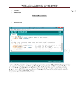
Use belowcode to displaymessage on LCD wirelesslyusingGSM
#include <LiquidCrystal.h>
LiquidCrystal lcd(2,4,8,9,10,11);
intled=13;
inttemp=0,i=0,x=0,k=0;
char str[100],msg[32];
voidsetup()
{
lcd.begin(16,2);
Serial.begin(9600);
pinMode(led,OUTPUT);
digitalWrite(led,HIGH);
lcd.print("GSMInitilizing...");
gsm_init();
lcd.setCursor(0,0);
lcd.print("WirelessNotice");
lcd.setCursor(0,1);
lcd.print(" Board ");
delay(2000);
17. WIRELESS ELECTRONIC NOTICE BOARD
Page | 17How to Operate?
1. Write the program for the wirelesselectronicnotice boardinclanguage.
2. Nowburn the programto the microcontrollerusingArduinoDroid
3. Give the connectionsasperthe circuitdiagram.
4. Use powersupplycircuittoprovide 5V DC to the microcontroller
5. Insertthe SIM(SubscriberIdentityModule) tothe GSMmodule.
6. Nowswitchon the supply
7. SendSMS to the GSM module usingothermobile
8. Nowyoucan see the same message onLCD
Output window
18. WIRELESS ELECTRONIC NOTICE BOARD
Page | 18
Circuit Advantages:
No needof anycomplex wirestodisplaythe messageonLCDas it is wireless.
Consume lesspowerandeasytooperate.
The circuit isportable.
One of the single mostimportantmediaforinformationtransfertothe maximumnumberof
users.
Thissystemcan avoidpaperwork, reduceshumaneffort
Circuit Applications:
Usedin busstations,railwaystations,parks,etc.todisplaythe messageswirelessly
ThisProjectisusedin collegesandorganizations.
In an fewsecondcantransfernotice to n numbers.
Circuit Limitations:
Display unitmusthave the networktoreceive the message wirelessly
As there isnopasswordany one can sendthe message todisplay.
Future of Project:
The use of microcontrollerinplace of ageneral purpose computerallowsustotheorize on
manyfurtherimprovementsonthisprojectprototype.
Temperature displayduringperiodswhereinnomessage buffersare emptyisone such
theoretical improvementthatisverypossible.
With properuse of interruptroutinesthe incomingmessage actsasan interrupt,the
temperature displayishaltedandthe control flow jumpsovertothe specificinterruptservice
routine whichfirstvalidatesthe sender’snumberandthendisplaysthe informationfield.
Anotherveryinterestingandsignificantimprovementwouldbe toaccommodate multiple
receiverMODEMS at the differentpositionsinageographical areacarryingduplicate SIMcards..
Multilingual displaycanbe anotheraddedvariationof the project.
19. WIRELESS ELECTRONIC NOTICE BOARD
Page | 19
Conclusion
GSM systemsisthe collaborationof software &hardware throughwhichmostof the complicityreduces,
evensystemssize &coastalsoreduced.Suchhumancreationput usspell boundthatwhya topicof
inventionistakenRoboticsdesign.The GSMbaseddigital notice boardsystemthatwe have createdhas
beeninpractical use invariouscompanieslike inconstructioncompaniesandresearchareas,railways,
college.
Reference
1. D Dalwadi,N Trivedi andA Kasundra(2011), Article inNationconference onrecenttrendsin
engineeringandtechnology,INDIA
2. http://www.edgefxkits.in/wireless-electronic-notice-board-using-gsm
3. RonaldK Jurgen“Automotive ElectronicHandbook”:New York:McGraw-Hill,2nded.,1999, Part
7 Chapter29.
4. http://www.electronicshub.org/wireless-electronic-notice-board-using-gsm/
5. www.atmel.com
6. https://www.elprocus.com/wireless-electronic-notice-board-using-gsm/