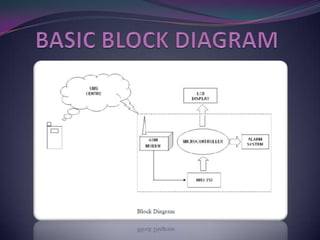
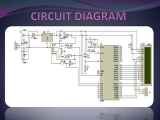
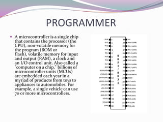
This document describes a mini project to create an anti-theft system for vehicles using GSM. It will use an ATMEL microcontroller and Motorola GSM modem to send SMS alerts to the owner's phone if the vehicle alarm is triggered. The system will work by programming the mobile phone with AT commands to send messages via the SIM card upon detection of unauthorized access or motion. Key components include the microcontroller, GSM modem, and LCD display. Challenges included fixing short circuits during soldering and replacing damaged parts.

![ SIM: It is a detachable smart card containing the
user's subscription information and phone book.
This allows the user to retain his or her
information after switching handsets [10].
Alternatively, the user can also change operators
while retaining the handset simply by changing
the SIM. Some operators will block this by
allowing the phone to use only a single SIM, or
only a SIM issued by them; this practice is known
as SIM locking, and is illegal in some countries .](https://image.slidesharecdn.com/gsmanti-theft-130130095606-phpapp02/85/Gsm-anti-theft-9-320.jpg)
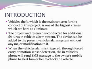
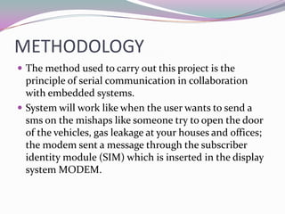
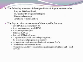
![LIST OF IMPORTANT AT
COMMANDS
The following are the ATCOMMAND used for programming the
GSM modem:
Example: Changing and saving parameters
AT+IPR=9600[Enter] Transfer rate to 9600bps
AT&W [Enter] save parameters
AT+CMGF means convert the message to machine instruction
format
AT+CPMS means selection of SMS memory
AT+CMGR means read message from a given memory location
AT+CMGD means delete message from a given memory location.](https://image.slidesharecdn.com/gsmanti-theft-130130095606-phpapp02/85/Gsm-anti-theft-14-320.jpg)


![Smart accident detector and intimator [autosaved]](https://cdn.slidesharecdn.com/ss_thumbnails/smartaccidentdetectorandintimatorautosaved-180331150920-thumbnail.jpg?width=640&height=640&fit=bounds)