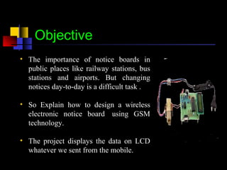
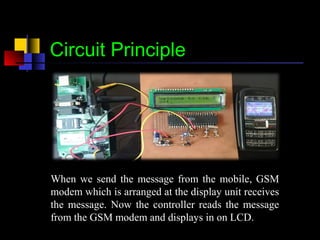
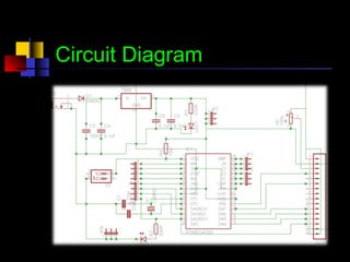
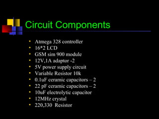
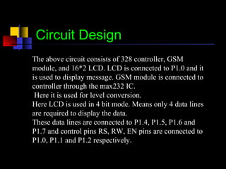
The objective of this project is ‘We know the importance of notice boards in public places like railway stations and bus stations. But changing notices day-to-day,time to time is a difficult task. so explains how to design a wireless electronic notice board using GSM technology.
3. Objective
• The importance of notice boards in
public places like railway stations, bus
stations and airports. But changing
notices day-to-day is a difficult task .
• So Explain how to design a wireless
electronic notice board using GSM
technology.
• The project displays the data on LCD
whatever we sent from the mobile.
4. Circuit Principle
When we send the message from the mobile, GSM
modem which is arranged at the display unit receives
the message. Now the controller reads the message
from the GSM modem and displays in on LCD.
7. Atmega 328 controller
• The Atmega328 is a very popular microcontroller chip
produced by Atmel. It is an 8-bit microcontroller that has32K
of flash memory, 1K of EEPROM, and 2K of internal SRAM.
• The Atmega328 has 28 pins. It has 14 digital I/O pins, of which
6 can be used as PWM outputs and 6 analog input pins.
• The Atmega328 is a low-power chip, so it only needs between
1.8-5.5V of power to operate. The Atmega328 chip has an
analog-to-digital converter (ADC) inside of it.
8. LCD( Liquid Crystal Display)
• A liquid crystal display (LCD) is a thin, flat display
device made up of any number of color or monochrome
pixels arrayed in front of a light source or reflector.
• If a 4-bit data bus is used the LCD will require 7 data
lines (3 control lines plus the 4 lines for the data bus).
• If an 8-bit data bus is used the LCD will require 11 data
lines (3 control lines plus the 8 lines for the data bus).
9. GSM Modem
A GSM modem is a wireless modem that
works with a GSM wireless network.
A wireless modem behaves like a dial-up
modem.GSM modem requires a SIM
card from a wireless carrier in order to
operate
dial-up modem sends and receives data
through a fixed telephone line while a
wireless modem sends and receives data
through radio waves.
A GSM modem is a wireless modem that works with a GSM wireless network.
10. Circuit Design
The above circuit consists of 328 controller, GSM
module, and 16*2 LCD. LCD is connected to P1.0 and it
is used to display message. GSM module is connected to
controller through the max232 IC.
Here it is used for level conversion.
Here LCD is used in 4 bit mode. Means only 4 data lines
are required to display the data.
These data lines are connected to P1.4, P1.5, P1.6 and
P1.7 and control pins RS, RW, EN pins are connected to
P1.0, P1.1 and P1.2 respectively.
11. Advantages
• No need of any complex wires to display
the message on LCD as it is wireless.
• Consumes less power and easy to operate.
• The circuit is portable.
12. Applications
•Used in bus stations, railway stations, parks, etc. to display the messages wirelessly
•This Project is used in colleges and organizations.
•Used in bus stations, railway stations, parks, etc. to display the messages wirelessly
•This Project is used in colleges and organizations.
•Used in bus stations, railway stations, parks, etc. to display the messages wirelessly
• Used in bus stations, railway stations, parks, etc. to
display the messages wirelessly.
• This Project is used in colleges an organizations.
13. Circuit Limitations
• Display unit must have the network to receive the
wirelessly.
• there is password any one can not send the message to
display.
• Only accept massage come with pass code.
*1234,------massage-----#