Downloaded 492 times
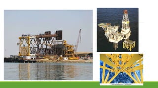
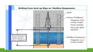
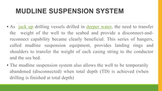
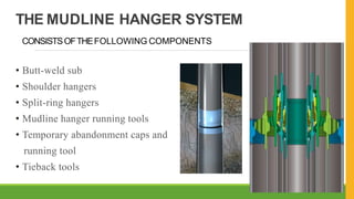

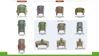
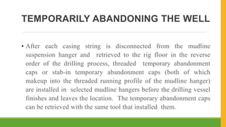
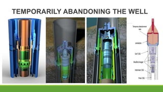
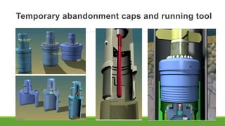
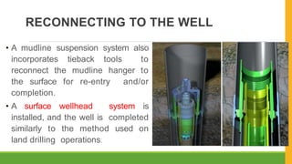
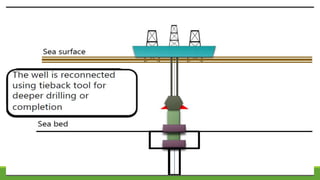
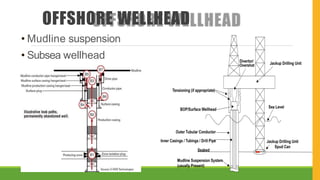
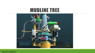


The document discusses mudline suspension systems used for offshore drilling. It describes how the system allows the weight of the well to be transferred to the seabed and provides a disconnect capability. Key components include butt-weld subs, shoulder hangers, split-ring hangers, mudline hangers, and temporary abandonment caps. The system also allows the well to be temporarily abandoned when drilling is finished and reconnected later for completion.


