Download as PDF, PPTX


![DESIGN FOR PRYING ACTION
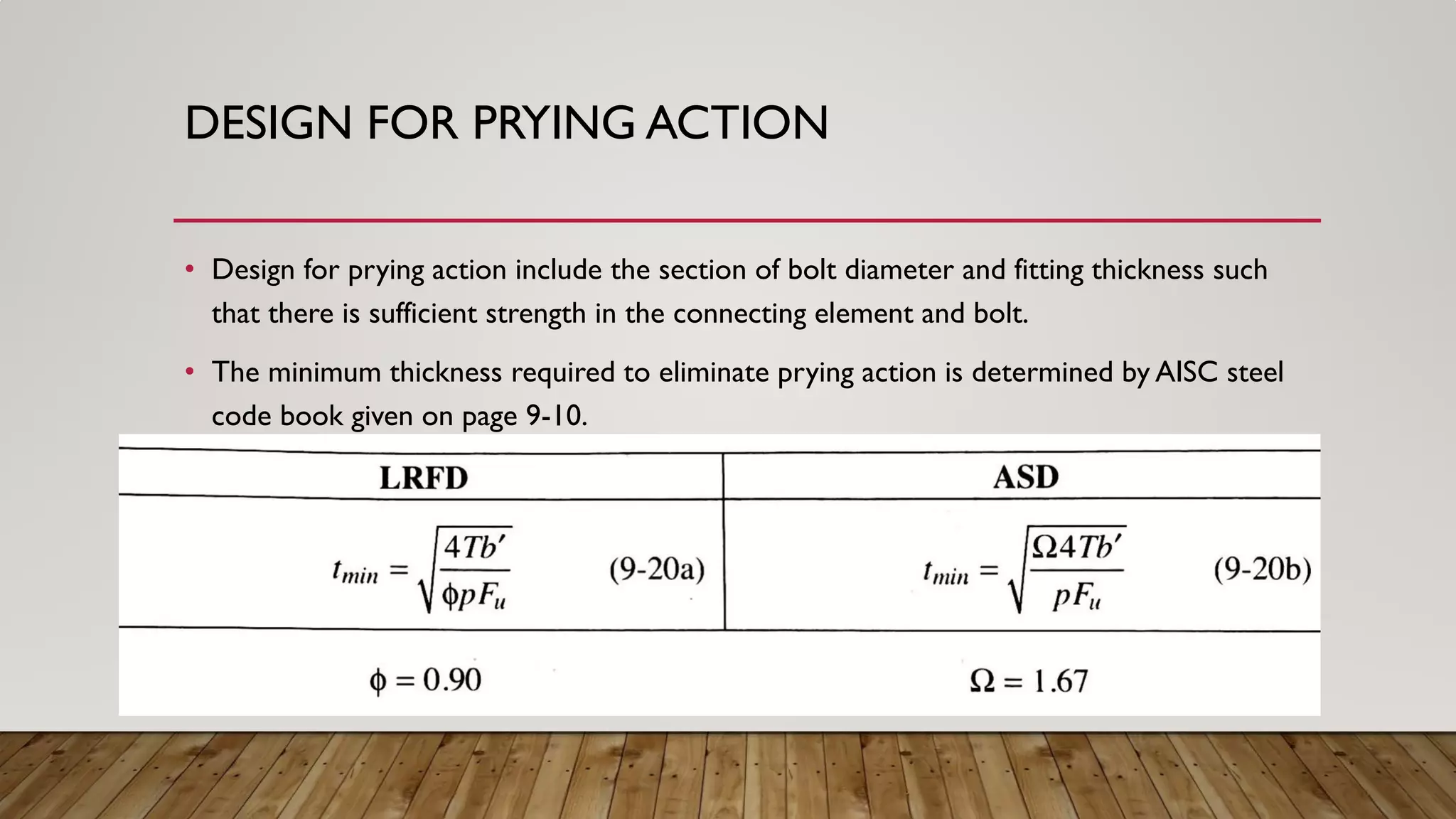
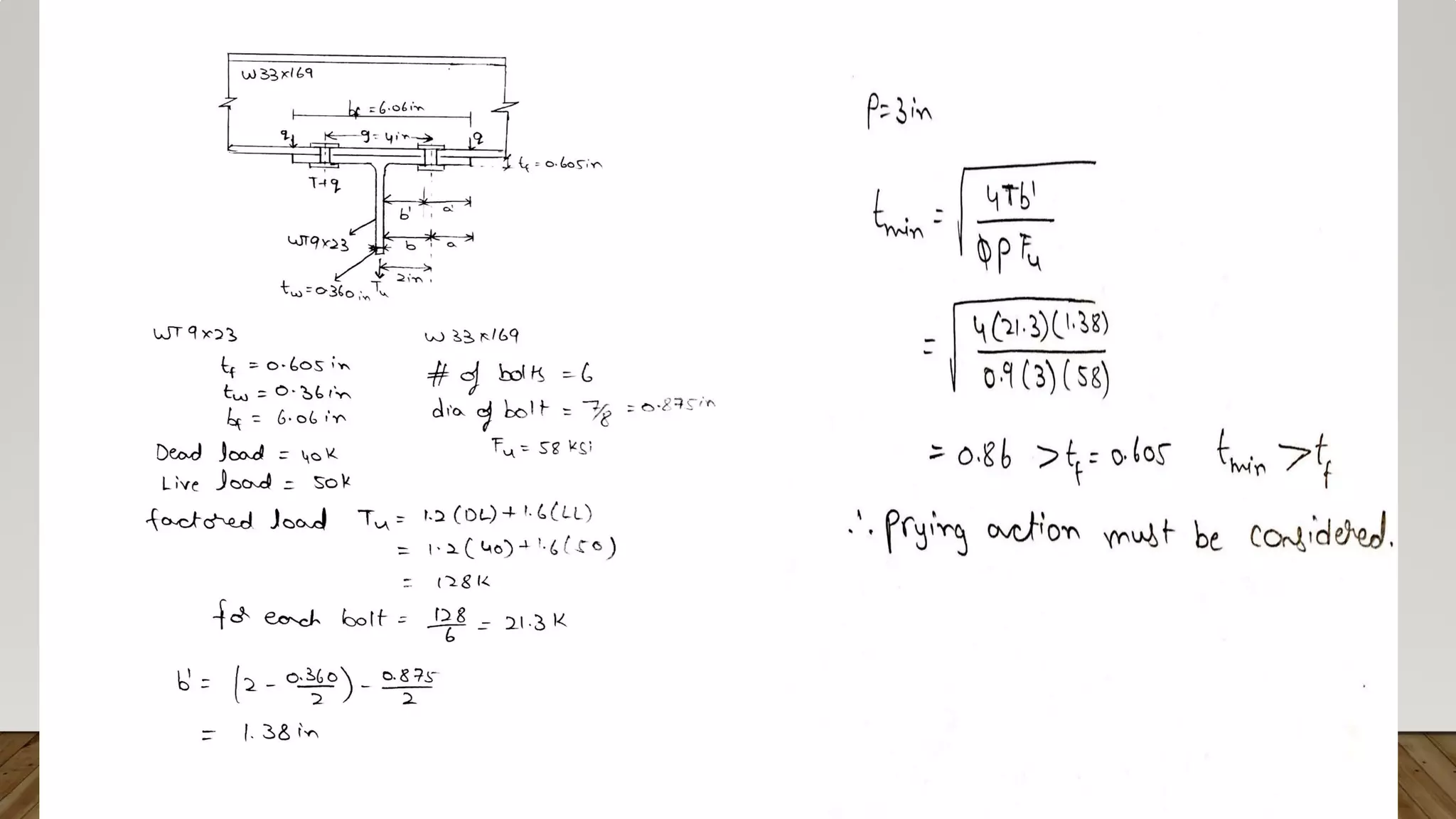
• The thickness required to ensure an acceptable combination of fitting strength and stiffness and bolt strength ,tmin
can be determined as
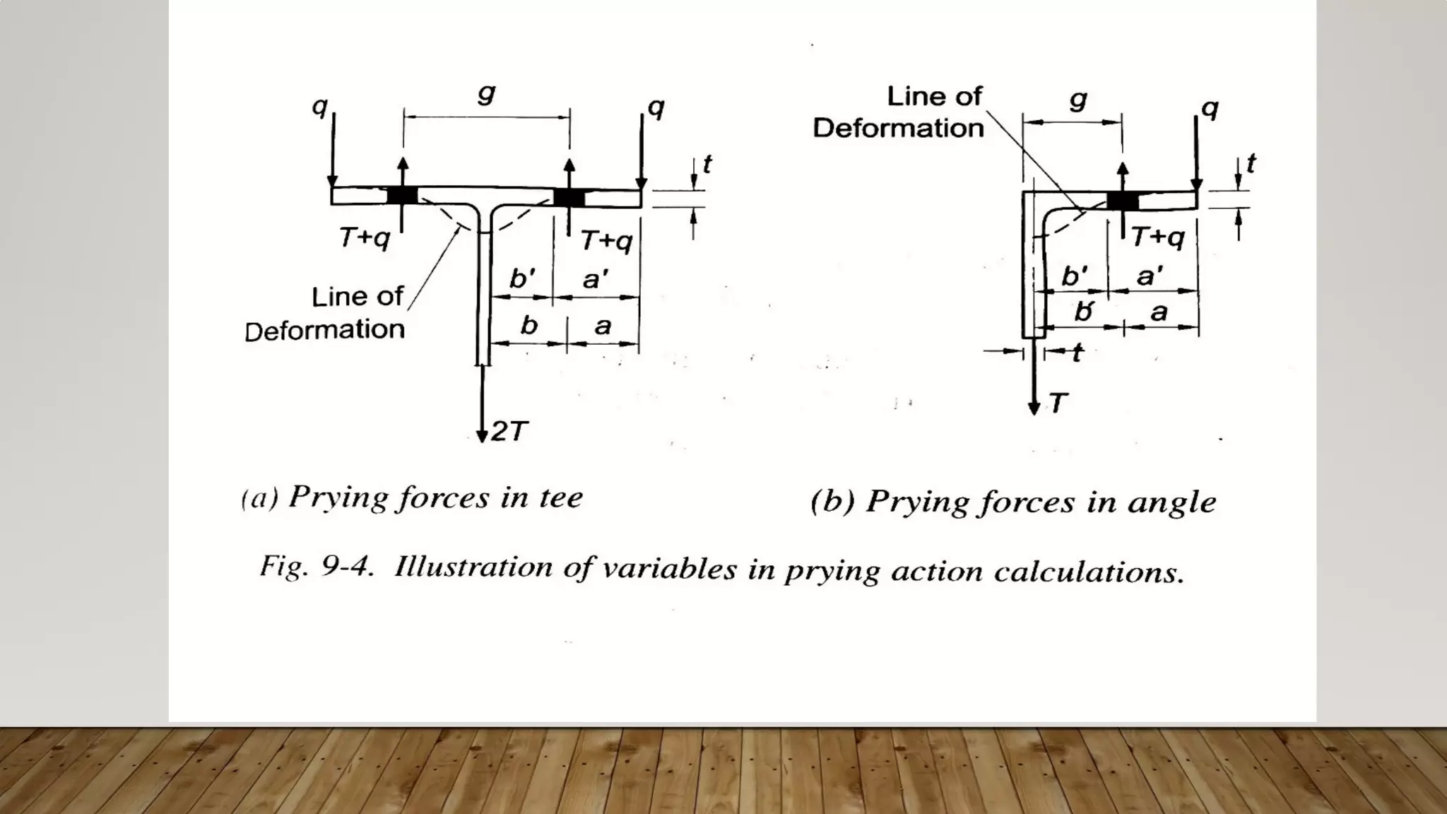
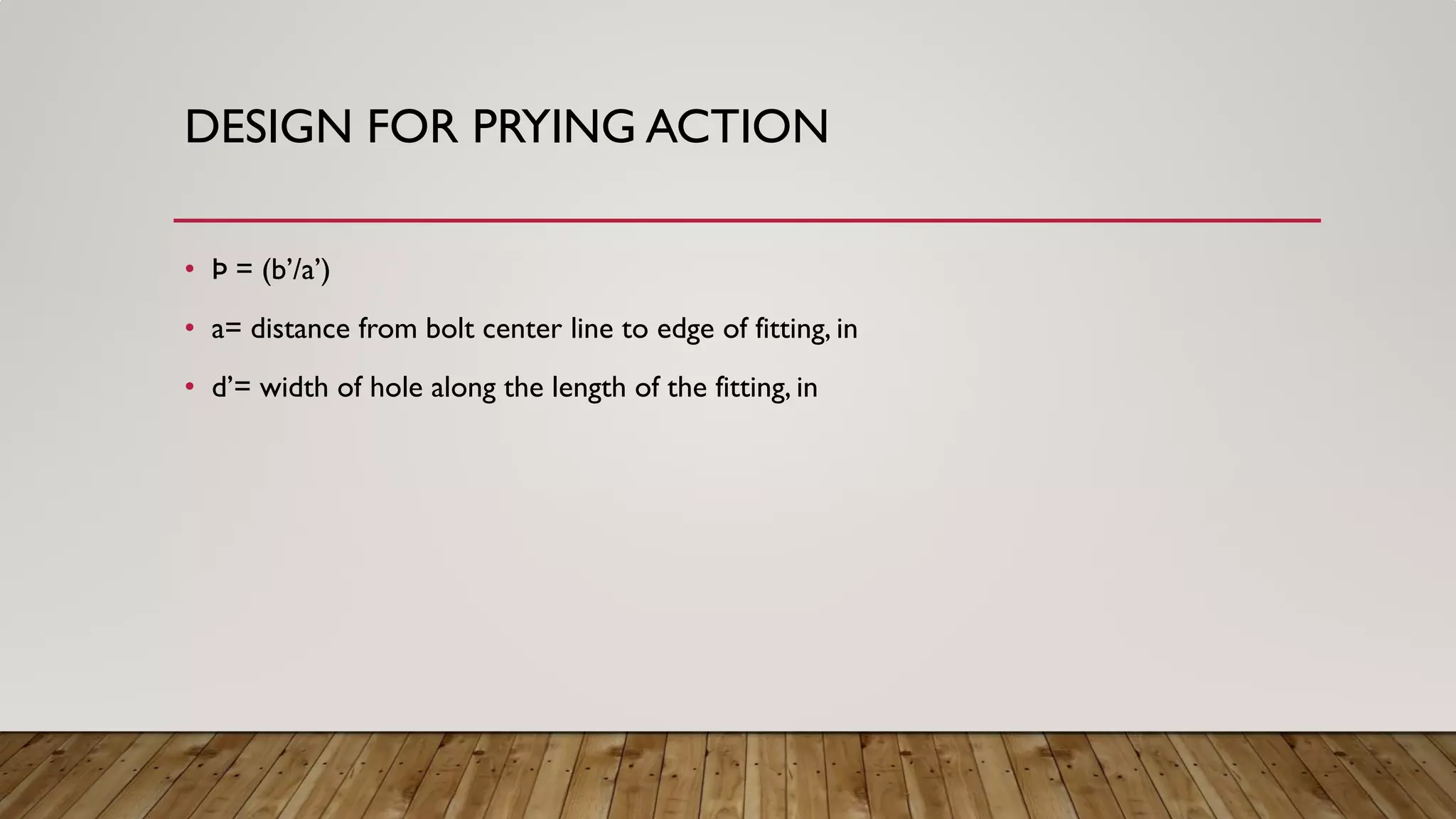
• ∂ = 1-(d’/p)= ratio of the net length at bolt line to gross length at the face of the stem or leg of angle.
• α‘ = 1.0 if β >= 1.0 ; the lesser of 1 and [1/ ∂ (β /1- β )] if β <1.0
• β = 1/ Þ (B/T -1) ; Þ = (b’/a’)
• B = available tension per bolt (from table 7-2)](https://image.slidesharecdn.com/koppoluabishek-pryingaction-170217181018/75/Koppolu-abishek-prying-action-10-2048.jpg)
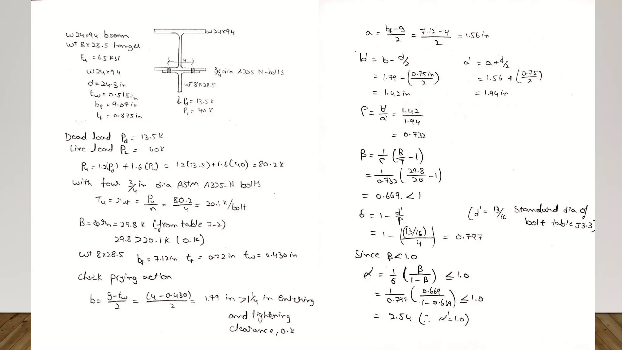
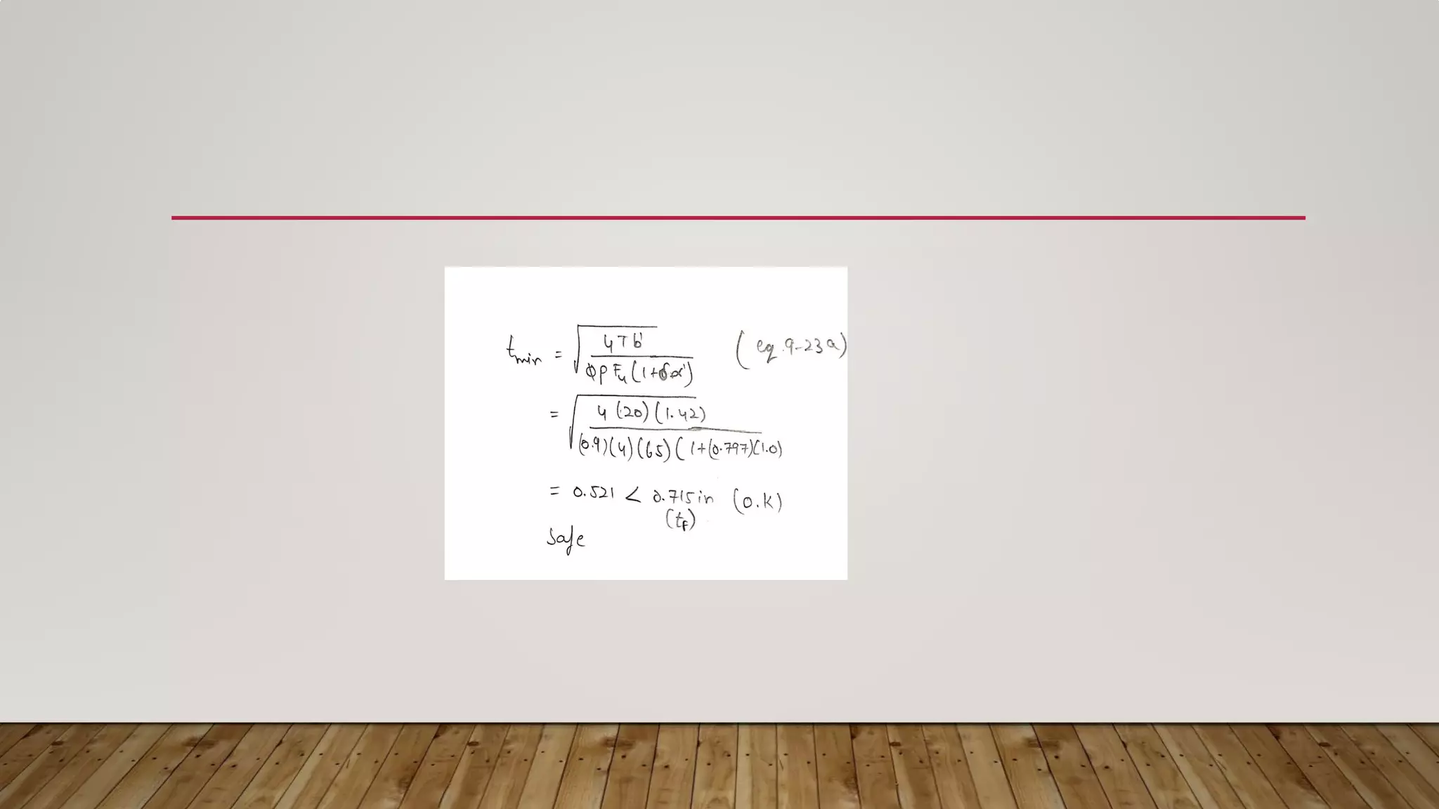
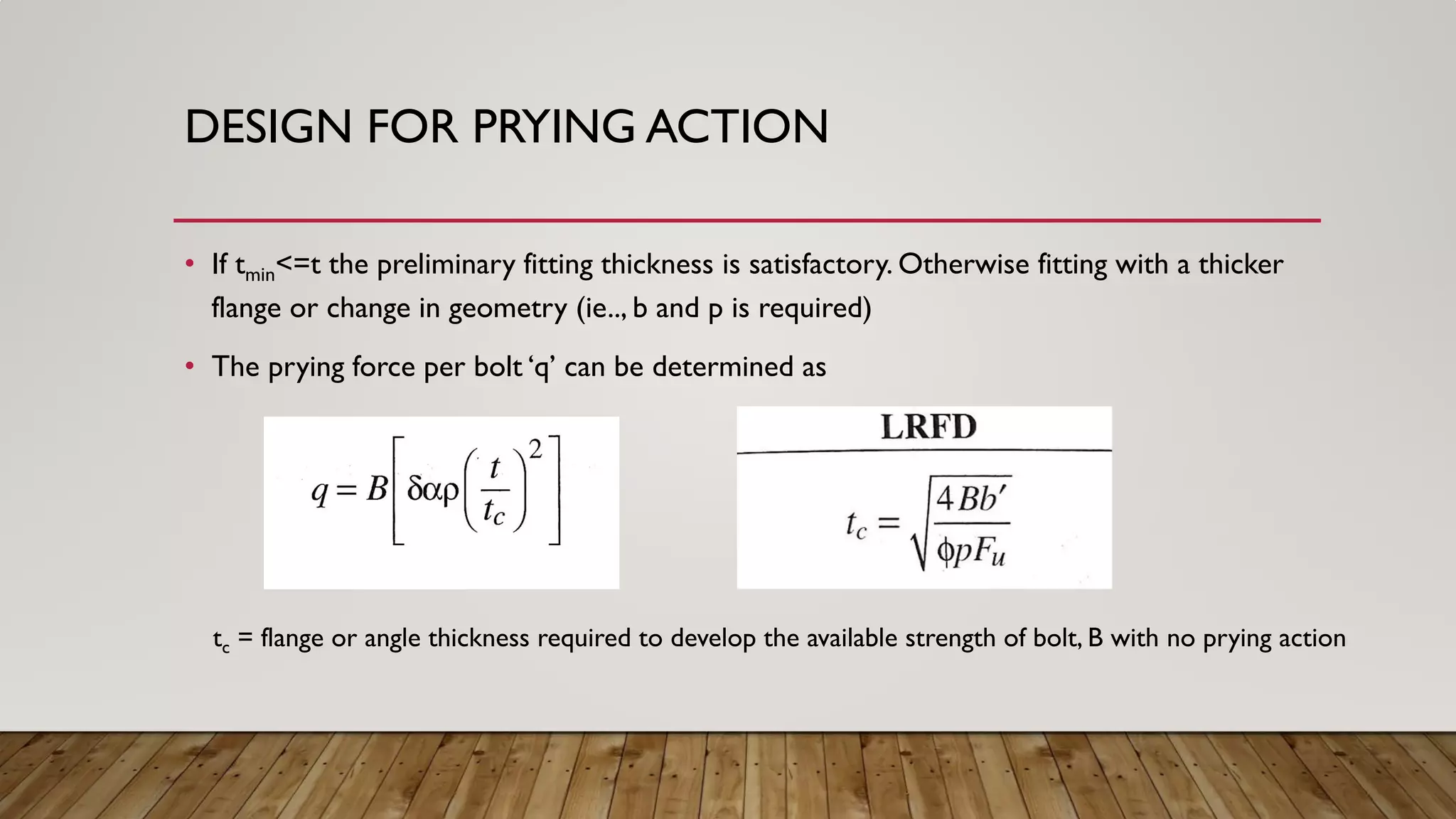
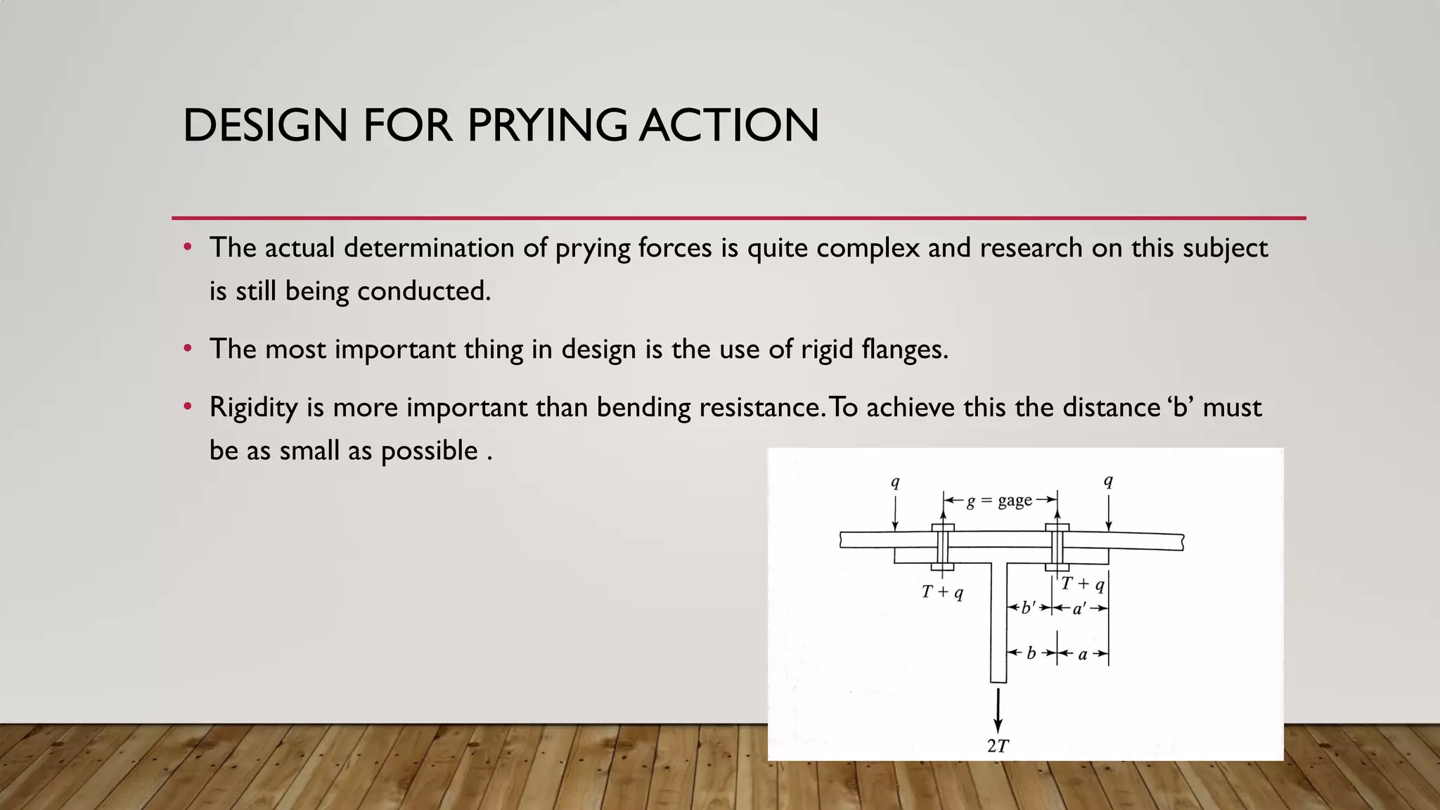


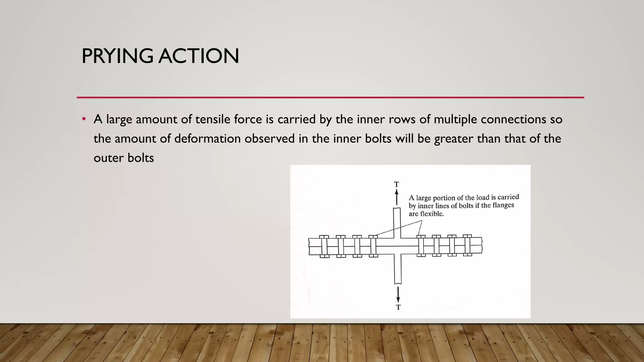
This document discusses prying action in bolted steel connections. Prying action occurs when the deformation of connected elements under tension increases the tensile force in bolts. It is affected by the strength and stiffness of the connection. The document outlines how to design for prying action by ensuring sufficient bolt diameter, fitting thickness, and distance between bolts. It provides examples calculating the required thickness to prevent prying action. It concludes that prying forces should be considered in design and sufficient rigidity of connected elements is most important.


![Geotechnical Engineering-II [Lec #9+10: Westergaard Theory]](https://cdn.slidesharecdn.com/ss_thumbnails/9-181020124827-thumbnail.jpg?width=640&height=640&fit=bounds)


