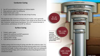
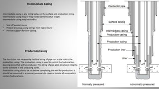
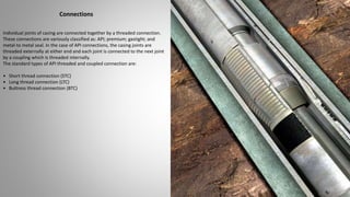
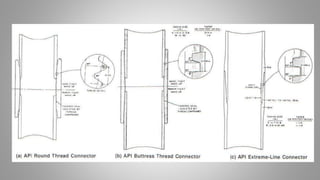
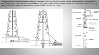
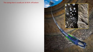
Ashley Manjoro
15-04-16
CASING
CASING PIPES
• Casing is large diameter pipe that is assembled and inserted into a recently drilled section of a well/borehole and typically
held into place with cement to protect and support the wellstream.
PURPOSE OF CASING
 Maintain hole integrity
 Isolate abnormally pressured zones
 Protect shallow weak formations from heavier mud weights required in the deeper portions of the hole
 Prevent contamination of freshwater-bearing strata
 Support unconsolidated sediments
WHAT IS CASING?
The conductor pipe is the first casing to be put in place, and is generally
installed before the rig arrives on location. Such casing can be driven to 250
feet. Conductor casing measuring between 16 to 24" outside diameter is
used onshore, and between 24 to 48" for offshore.
Conductor Casing
 Sea off unconsolidated formations at shallow depths
 Stop washouts under the drilling rig.
 Protect fresh water sands.
 To give a base and support for the next string of casing
Surface Casing
 Protect, water sands
 Support the wellhead and BOP equipment
 Case unconsolidated formations
 Support other casings
 Case off lost circulation zones
Surface casing is the first string of casing used after the conductor pipe. It is
required in some instances by law (to protect ground water) and is normally
cemented full length. Surface casing supports the BOP stack and subsequent
casing and tubing strings, and is normally the only string designed to carry
compression loads.
The fourth but not necessarily the final string of pipe run in the hole is the
production casing. The production casing is used to control the hydrocarbon
bearing zones that will be produced. This string of pipe adds structural integrity
to the wellbore in the producing zones.
Production casing should be set before completing the well for production. It
should be cemented in a manner necessary to cover or isolate all zones which
contain hydrocarbons.
Production Casing
Intermediate casing is any string between the surface and production string.
Intermediate casing may or may not be cemented full length.
Intermediate casing may be used to:
• Seal off weaker zones
• Protect previous casing strings from higher Burst
• Provide support for liner casing.
Intermediate Casing
The size of the casing refers to the outside diameter (O.D.) of the main body of the tubular (not the connector). Casing sizes vary
from 4.5" to 36" diameter. Tubulars with an O.D. of less than 4.5” are called Tubing.
API Standard
Casing Length
The API standards recognize three length ranges for casing:
 Range 1 (R-1): 16 – 25 ft.
 Range 2 (R-2): 25 – 34 ft.
 Range 3 (R-3): > 34 ft.
Casing is run most often in R-3 lengths to reduce the number of connections in
the string. Since casing is made up in single joints, R-3 lengths can be handled
easily by most rigs.
 Sometimes the well is drilled in stages called a casing program.
 Here, a well is drilled to a certain depth, cased and cemented, and then the well is drilled to a deeper depth, cased and
cemented again, and so on.
 Each time the well is cased, a smaller diameter casing is used.
 The widest type of casing is Conductor pipe (30 to 42 inches for offshore wells and 16 inches for onshore wells).
 The next size in casing string is the surface casing, which can run several thousands feet in length.
 In some wells, protection or intermediate casing is run to separate challenging areas or problem zones( Area of high pressure or
lost circulation)
 The last type of casing string run into the well , and smallest in diameter, is the Production or oil string.
 The Oil string runs directly into the producing reservoir.
Casing programs
Connections
Individual joints of casing are connected together by a threaded connection.
These connections are variously classified as: API; premium; gastight; and
metal-to metal seal. In the case of API connections, the casing joints are
threaded externally at either end and each joint is connected to the next joint
by a coupling which is threaded internally.
The standard types of API threaded and coupled connection are:
• Short thread connection (STC)
• Long thread connection (LTC)
• Buttress thread connection (BTC)
Casing leaks are often caused by damaging the threads while handling and running the casing on the rig. It has also been known for a joint of the wrong weight or
grade of casing to be run in the wrong place, thus creating a weak spot in the string. Such mistakes are usually very expensive to repair, both in terms of rig time and
materials. It is important, therefore, to use the correct procedures when running the casing.
.
The casing shoe is usually set 10-30 ft. off bottom

Casing

  • 1.
  • 2.
    • Casing islarge diameter pipe that is assembled and inserted into a recently drilled section of a well/borehole and typically held into place with cement to protect and support the wellstream. PURPOSE OF CASING  Maintain hole integrity  Isolate abnormally pressured zones  Protect shallow weak formations from heavier mud weights required in the deeper portions of the hole  Prevent contamination of freshwater-bearing strata  Support unconsolidated sediments WHAT IS CASING?
  • 3.
    The conductor pipeis the first casing to be put in place, and is generally installed before the rig arrives on location. Such casing can be driven to 250 feet. Conductor casing measuring between 16 to 24" outside diameter is used onshore, and between 24 to 48" for offshore. Conductor Casing  Sea off unconsolidated formations at shallow depths  Stop washouts under the drilling rig.  Protect fresh water sands.  To give a base and support for the next string of casing Surface Casing  Protect, water sands  Support the wellhead and BOP equipment  Case unconsolidated formations  Support other casings  Case off lost circulation zones Surface casing is the first string of casing used after the conductor pipe. It is required in some instances by law (to protect ground water) and is normally cemented full length. Surface casing supports the BOP stack and subsequent casing and tubing strings, and is normally the only string designed to carry compression loads.
  • 4.
    The fourth butnot necessarily the final string of pipe run in the hole is the production casing. The production casing is used to control the hydrocarbon bearing zones that will be produced. This string of pipe adds structural integrity to the wellbore in the producing zones. Production casing should be set before completing the well for production. It should be cemented in a manner necessary to cover or isolate all zones which contain hydrocarbons. Production Casing Intermediate casing is any string between the surface and production string. Intermediate casing may or may not be cemented full length. Intermediate casing may be used to: • Seal off weaker zones • Protect previous casing strings from higher Burst • Provide support for liner casing. Intermediate Casing
  • 5.
    The size ofthe casing refers to the outside diameter (O.D.) of the main body of the tubular (not the connector). Casing sizes vary from 4.5" to 36" diameter. Tubulars with an O.D. of less than 4.5” are called Tubing. API Standard Casing Length The API standards recognize three length ranges for casing:  Range 1 (R-1): 16 – 25 ft.  Range 2 (R-2): 25 – 34 ft.  Range 3 (R-3): > 34 ft. Casing is run most often in R-3 lengths to reduce the number of connections in the string. Since casing is made up in single joints, R-3 lengths can be handled easily by most rigs.
  • 6.
     Sometimes thewell is drilled in stages called a casing program.  Here, a well is drilled to a certain depth, cased and cemented, and then the well is drilled to a deeper depth, cased and cemented again, and so on.  Each time the well is cased, a smaller diameter casing is used.  The widest type of casing is Conductor pipe (30 to 42 inches for offshore wells and 16 inches for onshore wells).  The next size in casing string is the surface casing, which can run several thousands feet in length.  In some wells, protection or intermediate casing is run to separate challenging areas or problem zones( Area of high pressure or lost circulation)  The last type of casing string run into the well , and smallest in diameter, is the Production or oil string.  The Oil string runs directly into the producing reservoir. Casing programs
  • 7.
    Connections Individual joints ofcasing are connected together by a threaded connection. These connections are variously classified as: API; premium; gastight; and metal-to metal seal. In the case of API connections, the casing joints are threaded externally at either end and each joint is connected to the next joint by a coupling which is threaded internally. The standard types of API threaded and coupled connection are: • Short thread connection (STC) • Long thread connection (LTC) • Buttress thread connection (BTC)
  • 9.
    Casing leaks areoften caused by damaging the threads while handling and running the casing on the rig. It has also been known for a joint of the wrong weight or grade of casing to be run in the wrong place, thus creating a weak spot in the string. Such mistakes are usually very expensive to repair, both in terms of rig time and materials. It is important, therefore, to use the correct procedures when running the casing. .
  • 10.
    The casing shoeis usually set 10-30 ft. off bottom