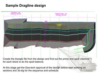
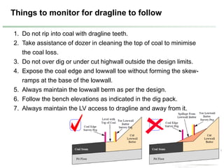
1. The document describes the dragline planning process which involves reviewing previous strip performance, geology, structures, access, and interactions to generate a dragline design.
2. Key steps include projecting coal edges and toe lines, offsetting lines, and using triangles between lines and profiles to create the highwall, lowwall, and spoil surfaces.
3. The design is then used to create a spoil balance, range diagrams, 3D dig model, and micro schedule for dragline digging.
subsidence, upsidence, subsidence limits, components of subsidence, prediction of subsidence, analysis of subsidence, coal mines, control of subsidence, subsidence trough, harmonic extraction, abandoned mines subsidence prevention, subsidence prevention in working coal mines, factors affecting subsidence
openings design in underground mines, different approaches, kirscha formulae for circular opening, plastic xzone effect on stability of opening, radial and tangential stresses distribution
Shovel and dumper combination is a type of heavy equipment used in open cast mining operations. It is composed of two separate machines, a front-end loader (shovel) and a backhoe (dumper). The shovel is used to scoop ore, rock, or other materials out of the mine, while the dumper carries the load to a designated area for further processing. This combination of machines allows for faster and more efficient mining operations, as the shovel can quickly scoop up large quantities of material, while the dumper can move the load quickly and safely. The shovel and dumper combination is an indispensable asset for any open cast mine, allowing for fast, efficient, and safe extraction of materials.
pillar design in coal mines, different pillar design approaches, salmon versus sheorey formulae, panel stability, diffrent approaches, local mine stiffness
Dragline machine at dhudhichua project ,singrauliTauhid Mohammad
A dragline excavator is a piece of heavy equipment used in civil engineering and surface mining.
Draglines fall into two broad categories: those that are based on standard, lifting cranes, and the heavy units which have to be built on-site.
Power shovel is a bucket equipped constuction equipment used for excavating and transporting all classes of earth (except solicd rocks without prior loosening) to nearby trucks or other hauling equipments.
Definition of Open pit Mining Parameters, Open pit Mining method, Bench, Open Pit Bench Terminology; Bench height; Cutoff grade; Open Pit Stability, Pit slope, Pit wall stability, Rock strength, Pit Depth, Pit diameter, Water Damage, Strip Ratio, Open-pit mining sequence, Various open-pit and orebody configurations; Ultimate Pit Definition, Manual Design, Computer Methods, Lerchs-Grossman method, Floating cone method; Open pit Optimization, The management of pit optimization, A simple example; The effects of scheduling on the optimal outline ; Optimum production scheduling; Materials handling Ex-Mine; Waste disposal; Dump design; Stability of mine waste dumps; Mine reclamation; Example of Open Pit Mining Methods
Its about drag line introduction , types ,methods and its working with some images and its very helpful in education and engineering students who have projected on construction equipment base topics.
Design optimization of excavator bucket using Finite Element MethodIjripublishers Ijri
An excavator is a typical hydraulic heavy-duty human-operated machine used in general versatile construction operations,
such as digging, ground leveling, carrying loads, dumping loads and straight traction. Normally backhoe excavators
are working under worst working conditions. Due to severe working conditions, excavator parts are subjected to
high loads and must work reliably under unpredictable working conditions. Thus, it is necessary for the designers to
provide not only an equipment of maximum reliability but also of minimum weight and cost, keeping design safe under
all loading conditions.
#تواصل_تطوير
المحاضرة رقم 187
أستاذ دكتور / مدحت كمال عبدالله
عنوان المحاضرة:
تدعيم كباري باستخدام التفاعل المشترك
للمياه - جسم الكوبري
وعرض حالة عملية
Temporary Support Of Existing Bridges Using
Water-Structure Interaction
including case study
يوم الإثنين 26 ديسمبر 2022
الثامنة مساء توقيت القاهرة
التاسعة مساء توقيت مكة المكرمة
و الحضور عبر تطبيق زووم من خلال الرابط
https://us02web.zoom.us/meeting/register/tZModeusrzsoHtbqmSpzcaX1yPR0TmfeoAQl
علما ان هناك بث مباشر للمحاضرة على القنوات الخاصة بجمعية المهندسين المصريين
ونأمل أن نوفق في تقديم ما ينفع المهندس ومهمة الهندسة في عالمنا العربي
والله الموفق
للتواصل مع إدارة المبادرة عبر قناة التليجرام
https://t.me/EEAKSA
ومتابعة المبادرة والبث المباشر عبر نوافذنا المختلفة
رابط اللينكدان والمكتبة الالكترونية
https://www.linkedin.com/company/eeaksa-egyptian-engineers-association/
رابط قناة التويتر
https://twitter.com/eeaksa
رابط قناة الفيسبوك
https://www.facebook.com/EEAKSA
رابط قناة اليوتيوب
https://www.youtube.com/user/EEAchannal
رابط التسجيل العام للمحاضرات
https://forms.gle/vVmw7L187tiATRPw9
ملحوظة : توجد شهادات حضور مجانية لمن يسجل فى رابط التقيم اخر المحاضرة.
Cable Stay Bridge construction at Bardhman using LARSA and LUSAS four dimensi...Rajesh Prasad
For the construction of Cable Stayed Bridge at Bardhman, a simulation model was made using LARSA 4D and accordingly design were concluded considering all the possible situation. At the execution stage the profile/geometry control is very important. Accordingly construction stage analysis along with geometry control is being done using LUSAS software. These software are 4D and the fourth dimension is Time. The said presentation covers the LARSA, LUSAS and few pictures on execution at site along with sample of documentation.
Analysis & Preliminary Design Of 3-span Continuous RCC Box Girder Bridge Deck with Parabolically Varying Depth Presentation slide for Civil Engineering final year students
Presentation on Flyover at Aziz Cross on GT Road GujranwalaRubnawaz Bhatti
Presentation on Flyover at Aziz Cross on GT Road Gujranwala. First project in the history of Pakistan where flyovers are constructed on different heights
Immunizing Image Classifiers Against Localized Adversary Attacksgerogepatton
This paper addresses the vulnerability of deep learning models, particularly convolutional neural networks
(CNN)s, to adversarial attacks and presents a proactive training technique designed to counter them. We
introduce a novel volumization algorithm, which transforms 2D images into 3D volumetric representations.
When combined with 3D convolution and deep curriculum learning optimization (CLO), itsignificantly improves
the immunity of models against localized universal attacks by up to 40%. We evaluate our proposed approach
using contemporary CNN architectures and the modified Canadian Institute for Advanced Research (CIFAR-10
and CIFAR-100) and ImageNet Large Scale Visual Recognition Challenge (ILSVRC12) datasets, showcasing
accuracy improvements over previous techniques. The results indicate that the combination of the volumetric
input and curriculum learning holds significant promise for mitigating adversarial attacks without necessitating
adversary training.
Hierarchical Digital Twin of a Naval Power SystemKerry Sado
A hierarchical digital twin of a Naval DC power system has been developed and experimentally verified. Similar to other state-of-the-art digital twins, this technology creates a digital replica of the physical system executed in real-time or faster, which can modify hardware controls. However, its advantage stems from distributing computational efforts by utilizing a hierarchical structure composed of lower-level digital twin blocks and a higher-level system digital twin. Each digital twin block is associated with a physical subsystem of the hardware and communicates with a singular system digital twin, which creates a system-level response. By extracting information from each level of the hierarchy, power system controls of the hardware were reconfigured autonomously. This hierarchical digital twin development offers several advantages over other digital twins, particularly in the field of naval power systems. The hierarchical structure allows for greater computational efficiency and scalability while the ability to autonomously reconfigure hardware controls offers increased flexibility and responsiveness. The hierarchical decomposition and models utilized were well aligned with the physical twin, as indicated by the maximum deviations between the developed digital twin hierarchy and the hardware.
Overview of the fundamental roles in Hydropower generation and the components involved in wider Electrical Engineering.
This paper presents the design and construction of hydroelectric dams from the hydrologist’s survey of the valley before construction, all aspects and involved disciplines, fluid dynamics, structural engineering, generation and mains frequency regulation to the very transmission of power through the network in the United Kingdom.
Author: Robbie Edward Sayers
Collaborators and co editors: Charlie Sims and Connor Healey.
(C) 2024 Robbie E. Sayers
Cosmetic shop management system project report.pdfKamal Acharya
Buying new cosmetic products is difficult. It can even be scary for those who have sensitive skin and are prone to skin trouble. The information needed to alleviate this problem is on the back of each product, but it's thought to interpret those ingredient lists unless you have a background in chemistry.
Instead of buying and hoping for the best, we can use data science to help us predict which products may be good fits for us. It includes various function programs to do the above mentioned tasks.
Data file handling has been effectively used in the program.
The automated cosmetic shop management system should deal with the automation of general workflow and administration process of the shop. The main processes of the system focus on customer's request where the system is able to search the most appropriate products and deliver it to the customers. It should help the employees to quickly identify the list of cosmetic product that have reached the minimum quantity and also keep a track of expired date for each cosmetic product. It should help the employees to find the rack number in which the product is placed.It is also Faster and more efficient way.
Final project report on grocery store management system..pdfKamal Acharya
In today’s fast-changing business environment, it’s extremely important to be able to respond to client needs in the most effective and timely manner. If your customers wish to see your business online and have instant access to your products or services.
Online Grocery Store is an e-commerce website, which retails various grocery products. This project allows viewing various products available enables registered users to purchase desired products instantly using Paytm, UPI payment processor (Instant Pay) and also can place order by using Cash on Delivery (Pay Later) option. This project provides an easy access to Administrators and Managers to view orders placed using Pay Later and Instant Pay options.
In order to develop an e-commerce website, a number of Technologies must be studied and understood. These include multi-tiered architecture, server and client-side scripting techniques, implementation technologies, programming language (such as PHP, HTML, CSS, JavaScript) and MySQL relational databases. This is a project with the objective to develop a basic website where a consumer is provided with a shopping cart website and also to know about the technologies used to develop such a website.
This document will discuss each of the underlying technologies to create and implement an e- commerce website.
Explore the innovative world of trenchless pipe repair with our comprehensive guide, "The Benefits and Techniques of Trenchless Pipe Repair." This document delves into the modern methods of repairing underground pipes without the need for extensive excavation, highlighting the numerous advantages and the latest techniques used in the industry.
Learn about the cost savings, reduced environmental impact, and minimal disruption associated with trenchless technology. Discover detailed explanations of popular techniques such as pipe bursting, cured-in-place pipe (CIPP) lining, and directional drilling. Understand how these methods can be applied to various types of infrastructure, from residential plumbing to large-scale municipal systems.
Ideal for homeowners, contractors, engineers, and anyone interested in modern plumbing solutions, this guide provides valuable insights into why trenchless pipe repair is becoming the preferred choice for pipe rehabilitation. Stay informed about the latest advancements and best practices in the field.
2. Dragline setup
Highwall Crest
Highwall Toe
Lowwall berm
Lowwall Crest
Lowwall Toe
Coal edge
KEY
Spoil Toe
Spoil
Cable boat
DL Cable
LV Park up
Direction of dig
DL boom radius + 30m
DL boom radius
Exclusion zone
BLOCK
TOP OF COALDe coaled
area
Call up Sign
4. Dragline Planning Process
1. It starts with Review of the recons of the previous strips considering the
below points.
• Dragline performance in the last strip – Prime, Rehandle, KPIs.
• Geological conditions – model variations with actual survey.
• Geological disturbances – faults, folds, intrusions, etc.
• Geotechnical structures – joint planes, highwall & lowwall stability,
failures, if any.
• Water management – low points, sump & pump locations.
• Drill and blast access.
• Coal access.
• Light vehicle access & cable access.
• Cable interactions.
• Dragline dig sequence.
• Spoil fit issues.
• Floor treatment – Ex. Floor blasting, Tuff push, etc
• Dragline entry and exit into the pit.
• Cast profiles.
5. Dragline Planning Process
2. Review the Geo-technical design parameters for highwall and lowwall for
angles and identify the potential areas of concerns. The general profile of
the dragline is as shown below.
TOPO Dragline designPrime
10m
10m
370
700
Presplit highwall
Highwall angle
HWC
HWT
CE LWT
LWC ST
SC
ST
370
Lowwall angle Spoil angle
SPOIL
Lowwall berm
SC
Max dump height=45m
Max dig depth=45m
Dragline horizon
HWC – Highwall Crest
HWT – Highwall Toe
CE – Coal Edge
LWT – Lowwall Toe
LWC – Lowwall Crest
ST – Spoil Toe
SC – Spoil Crest
LEGEND
6. Dragline Planning Process
2. Take the coal edge from the previous strip on floor of coal and offset it by 3m
and then normalise the line. If seam thick ness is more than 5m then reduce
the offset distance. As the seam thickness is 10m in this mine, so there is no
offset from the floor Coal edge. Hence normalise the coal edge line to get rid
of all the kinks in the line before projecting up to lowwall crest.
Coal edge line on Floor of Coal – As indicated by Survey
3m-Offset
Normalised line
without many kinks
Project this line
Project this line with Lowwall batter angle to a certain RL initially, may be 100m
high from the current coal edge RL. Then create a triangle surface (call
LW_37Batter) with these two lines to generate the Lowwall batter profile,
which will be used later to create Lowwall Toe & Crest lines.
PLAN SECTION
HWT-FloorofCoal
Coaledge-FOC
Offsetline-normalised
ProjectedtocertainRL
370
LW batter angle
Highwall Toe line on FOC- mostly taken from the medium term designs
Strip width=60m
7. Dragline Planning Process
3. Project the highwall Toe to the current Topo with the highwall batter angle. The
highwall batter angle is recommended by the Geo-tech analysis with a minimum
factor of safety 1.2. In a highly faulted areas, it is recommended to have a softwall
batter of 45 degrees rather than a presplit wall with 65 or 70 degree batter. Do the
same for endwall.
4. As the dragline exposes to top of coal so create the highwall toe line on TOC
and also take the coal edge line of the previous strip on the lowwall side from the
actual survey. Create the contours of the top of coal within this polygon.
SECTION
HWT
HWCHWC
CE
TOPO
Softwall – 450
Presplit wall – 650 to 700
CE
Previous strip
highwall
8. Dragline Planning Process
5. Offset the Coal edge line on TOC by 50m towards lowwall and create a triangle
using CE-TOC and offset line which will intersect with the lowwall batter profile
created earlier. The intersection of these two triangles will give you the lowwall toe
line.
HWC
HWT - TOC
TOC Contours
CE - TOC
CE - FOC
CE – TOC – Offset by 50m
Triangle with CE-TOC and 50m offset line
Lowwall batter profile
SECTION
HWC
HWT - TOC
CE - TOC
CE - FOC
CE – TOC – Offset by 50m
Triangle with line-1 & 2 (Surface-2)
LWT Line
Intersection between Surface -1 & 2 will
give the Lowwall Toe line.
Lowwall
Toe
1 2
Section line
9. Dragline Planning Process
SECTION
HWC
HWT - TOC
CE - TOC
CE - FOC
LWT
Project the HWT-TOC line 90
degrees at a distance equal to
max dig depth of DL = 45m
Offset this line by 200m towards lowwall
Triangle surface with line-1 & 2 (Surface-2)
1 2
Intersection between Surface -1 & 2 will
give the Lowwall Crest line.
Lowwall
Crest
6. To create the lowwall crest line, project the Highwall Toe line at 90 degrees
vertical to an height equal to maximum dig depth of the dragline which is 45m in
this case and offset it by 200m towards lowwall. Generate the triangle with these
two lines and create an intersection line between this triangle and lowwall batter
profile to give you the lowwall crest line.
10. Dragline Planning Process
7. Then the remaining portion of the design process is to create the spoil.
1. Offset the lowwall crest line by 10m towards lowwall (which is the lowwall berm width,
it is different for different mines as recommended by the geo-tech analysis) which is
the spoil toe line.
2. Project this line at Spoil batter angle (which is 37 degrees – natural angle of repose,
this is also given by Geo-tech) to the maximum dump height of the dragline which is
45m in this case which gives the spoil crest line.
3. Then offset this line by 10m towards lowwall to give you the flat top of spoil &
4. Project down at 37 degrees to the topo to complete the design.
SECTION
HWC
TOPO
CE
HWT
LWC
ST
SC SC
ST
LWT
1
2
3
4
11. Sample Dragline design
HWC
HWT - TOC
CE - TOC
LWT
LWC
ST
SC
SC
ST
SOFTWALL – 450
HIGHWALL BATTER PRESPLIT WALL – 700
HIGHWALL BATTER
LOWEST
POINT
Create the triangle file from the design and find out the prime and spoil volumes
for each block to do the spoil balance.
At this stage get the Geo-tech approval of the design before start working on
sections and 3d-dig for the sequence and schedule.
12. ● The dragline horizon in this cross section can be calculated using the following
formula:
𝑆𝑝𝑜𝑖𝑙 𝐴𝑟𝑒𝑎
1.25
÷ 𝑆𝑡𝑟𝑖𝑝 𝑊𝑖𝑑𝑡ℎ = 𝐷𝑟𝑎𝑔𝑙𝑖𝑛𝑒 𝐻𝑜𝑟𝑖𝑧𝑜𝑛
Dragline horizon - Volumes
Dragline Horizon
Strip Width
Spoil Area
Pre-strip
A
B
A = Prime = Topo – Design surface (find out for each block, this is in bcm)
B = Spoil = Design surface – Topo
(find out for each block, this is in lcm. Divide by swell to convert to bcm)
13. Spoil Balance
Fill the spoil balance sheet with Prime, Spoil room, Top of coal RLs, Seam dips,
Highwall, Lowwall batters, lowwall berm width, Spoil strike lengths, etc. Which
populates the spoil fit condition in each block. Then play with the Key, elevated
and double elevated bench elevations to make the spoil to fit. Sample sheet is
shown below.
Based on the bench
elevations decide the
sequence of digging and
ramp locations between the
benches. Think of the cable
and LV access all the time.
14. Range Diagrams
Based on the spoil balance sheet, cut the sections in each block for every 100m
to find out the approximate cast volumes, dozer push volumes, dragline prime
and rehandle volumes. As this is based on the 2D plane, it is difficult to predict
the rehandles in cases like rolling the bridges and crossing the central ramps,
etc.
15. Range Diagrams
Range diagrams can be done using different software like Vulcan, Minescape,
Drag sim, etc. A sample range diagram done using Minescape is shown below.
16. 3d-dig – Dig Pack & Schedule
1. Based on spoil balance and Range diagrams adjust the lowwall crest elevations for the
design and build the new spoil from this changed lowwall crest line.
2. Export the Pre dig DTM with Pre-strip removed, dragline design, Coal seam roof & floor
into DXF format and then import all of them into 3d-dig.
3. Create the approximate blast profile in 3d-dig from the sections and blast the material
with the historical swell factor of the area and then start digging using dragline with a
dig swell of 5%.
4. Follow the sequence discussed during the spoil balance step and finish the dig.
5. Export the volumes (lcm) from 3d-dig and convert them to bcm to make a schedule with
the given dragline KPIs. Supply the schedule to the medium term scheduler.
EP07 - DL Micro Schedule 17-Mar-16
Blocks Design Extra
Volume Delay D N D N D N D N D N D N D N D
17 17 18 18 19 19 20 20 21 21 22 22 23 23 24
DL Walk in to the main pass dig2,734,192 2,734,192 0 - 1 0 0.0 17-Mar AM 17-Mar AM 1 0 0 0 0 0 0 0 0 0 0 0 0 0 0
DE01 WALK 0 0 - 1 0 1.0 1.0 17-Mar AM 17-Mar PM 1 1 0 0 0 0 0 0 0 0 0 0 0 0 0
DE01 13 KEY 82,017 82,017 2,200 9.41 1 41,387 4.0 17-Mar PM 19-Mar AM 0 1 1 1 1 0 0 0 0 0 0 0 0 0 0
DE01 12 KEY 115,026 115,026 2,200 9.41 1 41,387 5.6 19-Mar AM 22-Mar AM 0 0 0 0 0 1 1 1 1 1 1 0 0 0 0
DE01 11 KEY 18,309 18,309 2,200 9.41 1 41,387 0.9 22-Mar AM 22-Mar PM 0 0 0 0 0 0 0 0 0 0 0 1 0 0 0
DE01 11 KEY 119,942 119,942 2,200 9.41 1 41,387 5.8 22-Mar PM 25-Mar PM 0 0 0 0 0 0 0 0 0 0 0 0 1 1 1
DE01 10 KEY 61,154 61,154 2,200 9.41 1 41,387 3.0 25-Mar PM 27-Mar AM 0 0 0 0 0 0 0 0 0 0 0 0 0 0 0
DE01 WALK - 0 0 - 1 0 1.0 1.0 27-Mar AM 27-Mar PM 0 0 0 0 0 0 0 0 0 0 0 0 0 0 0
DE01 13 BLKS 60,987 60,987 2,400 9.41 1 45,149 2.7 27-Mar PM 28-Mar PM 0 0 0 0 0 0 0 0 0 0 0 0 0 0 0
DE01 12 BLKS 115,214 115,214 2,400 9.41 1 45,149 5.1 28-Mar PM 31-Mar AM 0 0 0 0 0 0 0 0 0 0 0 0 0 0 0
DE01 11 BLKS 179,376 179,376 2,400 9.41 1 45,149 7.9 31-Mar AM 4-Apr AM 0 0 0 0 0 0 0 0 0 0 0 0 0 0 0
DE01 10 BLKS 20,205 20,205 2,400 9.41 1 45,149 0.9 4-Apr AM 4-Apr PM 0 0 0 0 0 0 0 0 0 0 0 0 0 0 0
DE01 9 OHAND 29,035 29,035 2,200 9.41 1 41,387 1.4 4-Apr PM 5-Apr PM 0 0 0 0 0 0 0 0 0 0 0 0 0 0 0
DE01 10 OHAND 64,959 64,959 2,200 9.41 1 41,387 3.1 5-Apr PM 7-Apr AM 0 0 0 0 0 0 0 0 0 0 0 0 0 0 0
DE01 WALK - 0 0 - 1 0 1.0 1.0 7-Apr AM 7-Apr PM 0 0 0 0 0 0 0 0 0 0 0 0 0 0 0
DE01 10 KEY 70,976 70,976 2,200 9.41 1 41,387 3.4 7-Apr PM 9-Apr AM 0 0 0 0 0 0 0 0 0 0 0 0 0 0 0
DE01 9 KEY 120,140 120,140 2,200 9.41 1 41,387 5.8 9-Apr AM 12-Apr AM 0 0 0 0 0 0 0 0 0 0 0 0 0 0 0
DE01 8 KEY 124,754 124,754 2,200 9.41 1 41,387 6.0 12-Apr AM 15-Apr AM 0 0 0 0 0 0 0 0 0 0 0 0 0 0 0
DE01 7 KEY 27,548 27,548 2,200 9.41 1 41,387 1.3 15-Apr AM 15-Apr PM 0 0 0 0 0 0 0 0 0 0 0 0 0 0 0
DE01 WALK - 0 0 - 1 0 1.0 1.0 15-Apr PM 16-Apr AM 0 0 0 0 0 0 0 0 0 0 0 0 0 0 0
DE01 10 BLKS 158,808 158,808 2,400 9.41 1 45,149 7.0 16-Apr AM 19-Apr PM 0 0 0 0 0 0 0 0 0 0 0 0 0 0 0
DE01 9 BLKS 175,458 175,458 2,400 9.41 1 45,149 7.8 19-Apr PM 23-Apr PM 0 0 0 0 0 0 0 0 0 0 0 0 0 0 0
DE01 8 BLKS 64,493 64,493 2,400 9.41 1 45,149 2.9 23-Apr PM 25-Apr AM 0 0 0 0 0 0 0 0 0 0 0 0 0 0 0
DE01 DELAY - 0 0 - 1 0 0.5 0.5 25-Apr AM 25-Apr PM 0 0 0 0 0 0 0 0 0 0 0 0 0 0 0
DE01 7 KEY 142,541 142,541 2,200 9.41 1 41,387 6.9 25-Apr PM 28-Apr PM 0 0 0 0 0 0 0 0 0 0 0 0 0 0 0
DE01 6 KEY 93,369 93,369 2,200 9.41 1 41,387 4.5 28-Apr PM 1-May AM 0 0 0 0 0 0 0 0 0 0 0 0 0 0 0
DE01 6 OHAND 8,711 8,711 2,200 9.41 1 41,387 0.4 1-May AM 1-May AM 0 0 0 0 0 0 0 0 0 0 0 0 0 0 0
DE01 5 OHAND 56,735 56,735 2,200 9.41 1 41,387 2.7 1-May AM 2-May PM 0 0 0 0 0 0 0 0 0 0 0 0 0 0 0
DE01 4 OHAND 79,089 79,089 2,200 9.41 1 41,387 3.8 2-May PM 4-May PM 0 0 0 0 0 0 0 0 0 0 0 0 0 0 0
DE01 DELAY - 0 0 - 1 0 0.5 0.5 4-May PM 4-May PM 0 0 0 0 0 0 0 0 0 0 0 0 0 0 0
DE01 4 KEY 98,412 98,412 2,200 9.41 1 41,387 4.8 4-May PM 7-May AM 0 0 0 0 0 0 0 0 0 0 0 0 0 0 0
DE01 5 KEY 157,313 157,313 2,200 9.41 1 41,387 7.6 7-May AM 11-May AM 0 0 0 0 0 0 0 0 0 0 0 0 0 0 0
DE01 6 KEY 61,187 61,187 2,200 9.41 1 41,387 3.0 11-May AM 12-May PM 0 0 0 0 0 0 0 0 0 0 0 0 0 0 0
DE01 WALK - 0 0 - 1 0 1.0 1.0 12-May PM 13-May AM 0 0 0 0 0 0 0 0 0 0 0 0 0 0 0
DE01 8 BLKS 54,428 54,428 2,400 9.41 1 45,149 2.4 13-May AM 14-May AM 0 0 0 0 0 0 0 0 0 0 0 0 0 0 0
DE01 7 BLKS 106,578 106,578 2,400 9.41 1 45,149 4.7 14-May AM 16-May PM 0 0 0 0 0 0 0 0 0 0 0 0 0 0 0
DE01 6 BLKS 150,998 150,998 2,400 9.41 1 45,149 6.7 16-May PM 20-May AM 0 0 0 0 0 0 0 0 0 0 0 0 0 0 0
DE01 5 BLKS 116,430 116,430 2,400 9.41 1 45,149 5.2 20-May AM 22-May PM 0 0 0 0 0 0 0 0 0 0 0 0 0 0 0
S S M
Week-12
bcm/day
Duration
(Shifts)
Start date End date
T FType
(K/T/B)
Left
Vol.(bcm)
Rate
(bcm/hr)
Op.
Hrs/Shift
# Eq.
T W
17. Wall Plan
1. Prepare a wall plan with all the information showing the plan, sections, volumes, check
list, dig sequence, faults, low spots, coal access and Sign-off. Make copies one for
machine, one for production and one for tech-services. Sample wall plan is given below.
18. Exporting the design into Titronics
1. Export the design into DXF under ACTIVE layer name.
2. Export the triangle file of the design into DXF with FINAL layer name.
3. Export other lines like block lines, text, chop line, misfires, sump location, etc into DXF
under STATIC layer name.
4. Create a long section line along highwall toe. The RL of this line should be at the lowest
RL of the design. Export this line into DXF with CENTRELINELONG layer name.
5. Create a cross section line in the centre of the design. The RL of the line should be
more than the maximum RL of the design, i.e. this line should be above the design
triangle. Export this line into DXF with CENTRELINECROSS layer name.
6. Open the Leica translator and open the ACTIVE dxf file first. Then overlay all other dxf
files on top of this. Don’t save it as dozer file, if you save it first as dozer file then all the
layers in Leica translator will be copied under one layer and if you create map file after
this then dragline doesn’t distinguish between the different layers. Hence, create a map
file first then create the dozer file.
7. When you create the map file the text becomes horizontal, which will be rectified by
editing the map file in notepad and replace the number besides “P” with the actual
angle read from the design software. The text in the map file will be saved in the last, so
edit for each text with correct text angle and then save.
8. Upload the file into IMS (Titronics) and check with the machine for both plan view and
section view.
19. Execution of the dig
1. Conduct the pre-dig meeting and discuss the plan with the operators to get
the inputs and sequence modifications.
2. Make pit tour on the first day of each crew start to explain the plan for the
week and any short term changes and sequence modifications and discuss
the alternate options to improve the performance.
3. Take lots of photos and create a diary to record all the events in the dig, which
will be useful for the next dig in the same location for better planning and
execution. Learn from the mistakes you made.
4. Involve the operators in the planning process for the next dig and plan for the
next dig while the current dig is under execution to make the plan more robust
and pool proof.
5. Communicate with the other team members about the progress and share the
experiences.
20. Things to monitor for dragline to follow
1. Do not rip into coal with dragline teeth.
2. Take assistance of dozer in cleaning the top of coal to minimise
the coal loss.
3. Do not over dig or under cut highwall outside the design limits.
4. Expose the coal edge and lowwall toe without forming the skew-
ramps at the base of the lowwall.
5. Always maintain the lowwall berm as per the design.
6. Follow the bench elevations as indicated in the dig pack.
7. Always maintain the LV access to dragline and away from it.
21. Reconciliation
1. After the dig is finished, prepare reconciliation sheet comparing the plan Vs
actuals listing
1. KPIs
2. Prime and Rehandle volumes.
3. Coal tonnes & losses.
4. Blasting data.
5. Geo-technical issues.
6. Water management issues.
7. Highwall and lowwall profiles.
8. Major delays.
2. Request drill and blast for the floor treatment, if required.