Downloaded 329 times


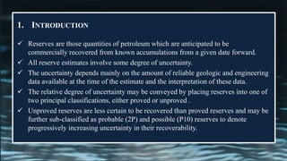


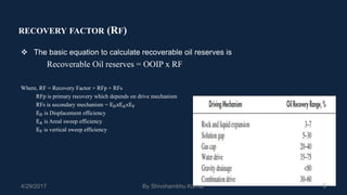
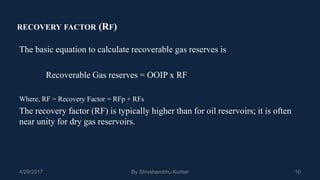


The document discusses the estimation of petroleum reserves using various methods, emphasizing the importance of geological and engineering data. It outlines the classifications of reserves into proved and unproved categories, detailing the factors influencing recoverability. Additionally, it explains the calculations for original hydrocarbon in place and recovery factors, alongside methodologies for forecasting production rates.