SlideShare a Scribd company logo
1 of 36
Download to read offline
Chapter 6 
DRILLING AND WELL 
CONSTRUCTION 
Gene Culver 
Geo-Heat Center 
Klamath Falls, OR 97601 
6.1 INTRODUCTION 
Drilling and well construction (probably one of the most 
expensive features of a geothermal direct use project) is often 
the least understood. This chapter provides the basics of 
equipment and methods used for drilling and completion of 
geothermal wells. It provides data needed by architects, 
engineers, and consultants to assist them in specification 
writing, selection of contractors, and drilling and completion 
inspection. 
Most direct use geothermal wells can be drilled using 
conventional water well technology and equipment. Most of 
the wells will produce water at temperatures less than boiling 
and without artesian flow at the surface; however, some will 
be hotter or will flow. Blowout preventers and other 
sophisticated safety equipment are not usually required; 
however, this does not mean that there are not significant 
safety considerations that should be addressed. Many of the 
wells have water above 140oF and this will scald. Public and 
drilling crew safety must be ensured. 
The cementing portion may appear to be overly detailed 
and long. However, the author's view is that, all too often, 
cementing is considered simply as a means of plugging up the 
annulus between the casing and borehole wall. Little attention 
is paid to methods and materials, and a poor cement job is the 
result. This can result in lost production zones, cold water 
leaking into production zones, geothermal water leaking into 
freshwater zones, and reduced useful well life. Also, in view 
of the increasing awareness and concern about inter-zonal 
migration and possible fresh water aquifer contamination, 
proper cementing is of increasing importance. 
A glossary of drilling terms is included at the end of this 
chapter. For some readers, it may be wise to read this section 
first in order to fully understand the text. 
6.2 DRILLING EQUIPMENT 
Two basic types of drilling rigs are used for drilling 
wells: cable tool (percussion) and rotary. There is just one 
basic cable tool rig, but there are several variations of rotary 
rigs. The following is a brief description of these rigs. 
6.2.1 Cable Tool 
This is not a drill in the common sense, because it is not 
power rotated. This drilling method uses a heavy bit that is 
repeatedly lifted and dropped that crushes and breaks the 
formation. Figure 6.1 shows the basic elements of a cable tool 
rig (Anderson & Lund, 1979). With a cable tool rig, an 
experienced driller can drill through any formation, including 
large crevices and caverns that can cause problems with other 
drilling methods. This method's main disadvantage is that it 
is slow. 
Drilling is accomplished with a tight drill line, as shown 
in Figure 6.1. The pitman arm and spudder beam impart an 
up-and-down motion to the cable and drill bit. The length of 
cable is adjusted so that on the down stroke the tools stretch 
the line as the bit hits the bottom of the hole, striking with a 
sharp blow and immediately retracting. The twist, or lay, of 
the cable imparts a slight turning motion to the tools so the bit 
hits a new face with each stroke. Left lay cable is used so that 
the twisting action tightens the tools screwed connections on 
each upstroke. If the borehole is dry, water is added to form 
a slurry that is bailed out. Usually about 5 ft of well hole is 
drilled between bailing. 
In consolidated formations, no casing is required for 
drilling. If the formation caves, 5 to 10 ft of hole is drilled; 
then casing with a drive shoe is driven to the bottom with 
driving clamps attached to the tools. With this casing in 
place, another 5 to 10 ft is drilled, and the operation is 
repeated again. Because the bit must be lowered through the 
casing, the diameter of the casing must be larger than the 
diameter of the bit. Driving the casing enlarges the hole and 
eventually friction prevents further advancement of the casing. 
Under these conditions, smaller casing is telescoped inside 
and drilling continues with a smaller bit. 
A method used to increase driving depth is to utilize an 
oversized drive shoe, slightly opening the hole. A bentonite 
slurry, placed around the casing, helps hold unconsolidated 
material in place and lubricates the casing. The bentonite also 
serves to seal leaks around the casing because of artesian 
pressure or differences in pressure in different aquifers. 
129
Sand line 
Sand reel 
Bull line 
reel 
Engine 
Power transform 
to pitman arm 
Spudder 
beam 
Drill line 
Ground surface 
Conductor pipe 
Spring or 
cushion 
Cement 
Surface casing 
Swivel 
Casing lap 
Drill stem 
Production casing 
Water level 
Open hole 
Drill bit 
Flat bottom 
bailer 
Dart bottom 
bailer 
Detail flat 
bottom bailer Detail dart 
bottom bailer 
Bailer dump 
box 
Drill cuttings 
Pin 
Pitman arm 
Figure 6.1 Basic elements of a cable tool drilling rig. 
Most states require cementing water well casings to the 
borehole wall down to some competent formation. In a 
geothermal well, it is usually cemented down to the 
geothermal zone to prevent mixing of geothermal fluids with 
shallower fresh surface waters. This also prevents mixing that 
reduces the water temperature. Any pipe driven down to that 
level must be considered a temporary casing and must be 
removed before or during cementing of the well. This places 
serious restrictions on any drill and drive technique. 
Although drilling is very time consuming at depths over 
1,500 to 2,000 ft, because of the time it takes to trip bailers 
and tools, deep holes can be drilled. The depth record is 
11,145 ft, completed in New York in 1953 (Campbell, 1973). 
Large rigs can drill 18 to 24 in. holes to several hundred 
feet. 
Cable tool rigs have several advantages over certain 
rotary methods: 
1. There is no potential for plugging producing formations 
with drilling muds. 
2. Rigs cost less, are simpler to maintain, and can be 
operated by one or two persons. Transportation and 
setup are easy and less water is required. 
3. Sampling and formation logging are simple and fairly 
accurate. There is little chance for contamination 
by previously drilled zones, especially in 
consolidated-formations. In unconsolidated forma-tions, 
there is always some chance the cable, tools, or 
bailer will wipe the side walls, carrying material down 
to be sampled later. 
130 
4. Qualitative and quantitative data can be obtained during 
drilling, including good flow estimates, and 
temperature, static water level, and water chemistry 
measurements. 
The disadvantages are: 
1. Depth and penetration rates are limited. 
2. Blowout preventers are not easily adapted. 
3. In unconsolidated formations, casing must be driven as 
the hole progresses. 
4. There is a lack of experienced personnel. Cable tool 
drilling is somewhat of an art and the preponderance of 
rotary drilling means a cable tool driller with wide 
experience may be hard to find. 
5. The method is limited to vertical holes. 
Accurate sampling, the ability to assess downhole 
conditions, and suspicion that drilling mud can adversely 
affect low- and moderate-temperature geothermal wells, are 
the reasons that some engineers are specifying the use of cable 
tool rigs in geothermal production zones. Holes are drilled to 
a specified formation, temperature, or simply the first lost 
circulation zone at elevated temperature, by conventional mud 
rotary method; then, the hole is completed using a cable tool 
rig. Temperatures can be measured at the surface, after water 
is brought up in the bailer. If the hole is deep and the static 
water level shallow, the measurements will only be 
approximate. Flows can be estimated from bailing rates. 
There is very little chance of mud and debris filling cracks 
and crevices in the producing zone. 
Although relatively high temperature bores have been 
successfully completed by continuous flooding with cold 
water, the method is not applicable: (1) where expected 
temperatures are higher than 250oF, (2) where significant 
artesian flows at the surface are expected, or (3) where depths 
are so great the cable tool rig is simply uneconomical. 
Unfortunately, it is not always easy to determine what is the 
best level in the borehole to change drilling methods. This 
problem will be discussed further under drilling fluids. 
6.2.2 Rotary Drilling 
Rotary drilling is the most common drilling method in 
both water and geothermal well drilling. There are several 
variations, each having their advantages and disadvantages. 
Figure 6.2 shows the basic elements of a conventional rotary 
mud rig.
Figure 6.2 Schematic diagram of a direct rotary rig 
illustrates the important operational 
components of this truck-mounted drilling 
machine. This machine, operating with 
either an air-based or water-based drilling 
fluid, can drill more rapidly than a cable 
tool rig (Gardner-Denver Co.) 
The drill bit, usually a tricone roller, is rotated by the 
hollow drill collar and drill pipe. Torque is applied through 
the rotary table and kelly. Drilling fluid is circulated down 
the drill pipe and out openings in the bit where it cleans 
cuttings from beneath the bit, cools the bit and carries 
cuttings to the surface where they are separated from the 
fluid. Weight on the bit is applied by the heavy drill collar 
assembly. The drill pipe is held in tension by the traveling 
block. Too much weight on the bit tends to drill crooked 
holes and, in some formations, slows down drilling because 
of insufficient cleaning action at the drilling face. 
Rigs with top head drive do not use a rotary table and 
kelly. Instead, a hydraulic motor that travels up and down 
the mast supplies torque directly to the drill pipe. Often a 
much shorter and lighter collar is used, and the rigs have 
pull-down chains to utilize part of the rig's weight at 
shallow depths. 
Although smaller in size than a large conventional 
rotary table rig, top head drives are capable of drilling most 
direct use wells. Rigs with masts and draw works capable 
of lifting 150,000 lb and with drives producing 140,000 in. 
lb of torque are available. 
Drilling fluids can be water, mud (water with 
additives such as bentonite, polymer, etc.), air and water 
(mists), air, or air and water with foaming agents. 
Conventional circulation means that the fluid goes down the 
drill pipe and up the annulus. When drilling with mists or 
air, the mud tank or pit is replaced by a cyclone-type 
separator. Air or mist drilling provides good formation 
sampling and can give reasonable estimates of geothermal 
fluid production. 
6.2.3 Other Types of Rotary Drilling 
Downhole Hammer 
One of the more popular methods for drilling 
geothermal wells is the air hammer method. It is especially 
suited to drilling hard igneous and metamorphic formations. 
It is not a true rotary method, but a percussion method adapted 
to a rotary rig. 
A pneumatic hammer, similar in action to a large jack-hammer, 
operates at the downhole end of the drill pipe on 100 
psi or higher compressed air. The hammer face has tungsten 
carbide inserts to provide chipping capabilities. Air hammers 
are available in 3 in. to at least 17 in. diameter and will 
provide between approximately 800 to 2,000 strokes/min. The 
drill pipe and hammer are rotated slowly so the inserts 
continually strike a new surface to provide even penetration 
and drill a straight hole. Hammer exhaust or excess air or 
both is directed to clean the chips away as they are formed, 
providing a clean surface and increasing drilling rates from 50 
to 100% faster than tricone rollers. The exhaust air carries 
cuttings up the annular space and out the hole. 
When drilling below static water level, pressure dif-ferences 
across the hammer must be maintained so air pres-sure 
is increased to accomplish this. Foams can be utilized to 
reduce the pressure in the borehole. Large hammers require 
large volumes of air at high pressures. Compressors and their 
operation significantly increase costs. 
Reverse Circulation 
In reverse circulation, drilling fluid (usually water or 
very thin mud) flows down the annulus, up the drill pipe to 
the suction side of a pump, and into the tank or pit. Cuttings 
are lifted inside the drill pipe that has a smaller cross section 
than the annulus. Suction lift of the pumps limits this method 
to approximately 450 ft depth at sea level (Driscoll, 1987). 
The method that is preferred for geothermal wells utilizes an 
air pipe inside the drill pipe to provide the lift, and a cyclone 
or similar separator to separate air from the water and cuttings 
mixture. The air lift greatly increases depth capacity. Fluid 
level in the annulus is maintained at or very near the surface. 
The drill pipe is similar to conventional air drilling pipe 
(Figure 6.3). 
The advantages of reverse circulation are: 
1. The reduction of velocity in the annulus reduces the 
possibility of wall erosion. 
131
Aerated fluid 
discharge with 
drill cuttings 
Air 
Drop pipe 
Swivel 
Rotary 
drive 
Fluid returns 
Static fluid level 
Figure 6.3 Reverse circulation drilling (Johnson 
Division, 1966). 
2. The increase in velocity up the drill pipe provides less 
time lag to the surface and less mixing of cuttings, 
which enhances sampling. 
3. Because water or very thin light mud is used, there is 
less possibility for formation damage by mud 
invasion. 
The disadvantages are: 
1. Large amounts of water can be required because there 
is very little or no filter cake to prevent losses to 
permeable zones. Fluid loss can be minimized by a 
good fluids program. 
132 
2. Since annulus fluid level is at the surface, it effectively 
prevents under-pressured geothermal fluid from entering 
the hole for detection by temperature or chemistry 
change. 
3. If geothermal fluid does enter, the chemistry can be 
changed by the large amount of air that effectively 
scrubs out carbon dioxide (CO2) and hydrogen sulfide 
(H2S), and may remove minor amounts of other species. 
A second reverse circulation method uses 6 in. or larger 
drill pipe and centrifugal or ejector pumps. Until recently, 
pipe joints were flanged, 10 in. or more in diameter, and holes 
were limited to about 16 in. or larger in order to maintain low 
fluid velocities around the flanges. Fragile, unconsolidated 
formations tended to wash out, sometimes creating small 
caverns around the flanges. This created serious problems 
in cementing the casing. Because of the large diameters, the 
method is not applicable to most geothermal wells, except 
possibly large water source heat pump wells. 
This method is most suited to drilling softer and 
unconsolidated formations and usually use drag bits, which 
cannot drill cobbles and boulders. Large roller bits are 
available, but expensive. Circulation rates of 500 gpm are not 
uncommon. Because of the large volume of water, special 
sampling boxes are recommended. 
Some newer reverse circulation pipe is threaded. This 
permits drilling smaller diameter holes with tricone bits, 
increases depth capability and speeds drilling because the time 
required to add or remove drill pipe sections is greatly 
reduced. 
A third reverse circulation system utilizes a dual-ducted 
swivel and special drill pipe to convert a conventional top 
head drive to a reverse circulation top head drive. 
Compressed air flows down through the swivel and special top 
coupling into pipes outside the drill pipe, then back to the 
main part of the drill pipe where it provides the lift for 
circulated fluid and cuttings. Fluid and cuttings flow up the 
drill pipe and out the second duct in the swivel. Conventional 
drill pipe is used between the point of air injection, which may 
be several hundred feet below ground surface, and the bit or 
collar. 
Drill Through Casing Driver 
Top head drive, direct circulation air rotary rigs can 
have casing drivers attached to the mast. The driver is similar 
to an air-driven pile driver. Using the driver, casing can be 
driven during drilling, similar to the drill and drive method 
used by cable tool rigs. Since sections of casing must be the 
same length as the drill pipe, they are usually pre-assembled. 
The bottom of the casing is equipped with a drive shoe.
Rotary 
drive 
Air discharge 
with drill 
cuttings 
Double-wall 
drill pipe 
Swivel 
Air 
Hammer sub 
Air to actuate hammer 
and remove cuttings 
Interchange sub 
Hammer 
Button bit 
When drilling unconsolidated formations, the bit fits 
inside the casing and the drive shoe shaves the formation 
during driving. Casing can be driven ahead of the bit which 
drills out the plug; or the bit can drill ahead of the casing, 
then be pulled back into the casing and casing driven; or the 
casing is driven just behind the bit at the same rate as bit 
penetration. Friction between the casing and borehole limits 
the amount of casing, of a given size, that can be driven. 
When it is necessary to set casing through a hard or well 
consolidated formation, an under-reaming bit, usually a 
downhole hammer, can be used. 
Because the casing seals off all but the near bottom 
formation cuttings, sampling is excellent, lost circulation 
problems are eliminated, and accurate estimates of water 
production can be obtained. 
The requirement for pulling the casing before cement-ing 
(similar to drill and drive cable tool) and the additional 
noise of the casing driver are the main disadvantages. 
Dual Tube Reverse Circulation 
This method is probably not applicable for most 
production wells because the largest outside tube diameter 
available is 9 5/8 in. It is, however, an excellent test well or 
pilot hole drilling method because it provides excellent cutting 
sampling and flow estimates. 
The drill pipe is double wall, usually flush jointed. 
Drilling fluid can be air, foam or light bentonite, or polymer 
muds. Fluid is circulated down between the pipe walls, 
through a bit sub, inward across the bit, picking up cuttings, 
and up through the inner pipe. The bit is normally one 
nominal size large than the outer pipe; therefore, a good seal 
between the pipe and well wall is obtained (Figure 6.4). 
Figure 6.4 Dual tube reverse circulation drilling (Johnson 
Division). 
When using a tricone bit, the distance between the bit 
and the bottom of the outer pipe is only a few inches, so 
samples are very representative of the formation actually being 
drilled. When using a downhole hammer, air flows through 
a hammer sub and the hammer, out the bottom of the hammer 
and up around the hammer to the sub where it is channeled to 
the inner pipe. The formation sample will be primarily from 
the hammer face, but the water samples could come from 
anywhere along the length of the hammer (Figure 6.5). 
Figure 6.5 Use of an interchange sub (Drilling Service 
Company). 
The cross-over channel in the interchange sub mounted 
on top of the hammer permits the cuttings to enter the inner 
casing. 
Drilling depth, limited by friction between the well wall 
and outer casing, can be approximately 2,000 ft in 
consolidated formations. 
6.2.4 Core Drilling 
Core drilling is basically an exploration method. This 
technique is widely used in mineral exploration, civil works 
foundation investigation, and wells for scientific investigation. 
It is also used for geothermal test and/or temperature gradient 
well drilling where accurate and complete lithology are 
required. It would rarely be used for production wells since 
the largest standard hole diameter is 4.828 in. and the method 
is very expensive. 
Core drilling equipment is designated by a letter size. 
Table 6.1 shows dimensions of core, hole, and drill rods for 
commonly used letter sizes (B, N, H, and P). 
133
Table 6.1 Common Core Sizes Normally Use for 
Geothermal Drilling 
______________________________________________ 
Drilling Equipment 
Designation B N H P 
Core size 1.432 1.875 2.500 3.345 
Hole size 2.360 3.040 3.850 4.828 
Drill rod ID 1.813 2.375 3.063 4.063 
Drill rod OD 2.188 2.750 3.500 4.625 
______________________________________________ 
There are several core drilling methods, but the usual 
method used in geothermal work is known as the wire line 
method. In this procedure, hollow drag-type bits with an ID 
of the core sizes and OD of the hole sizes, as shown in Table 
6.1, are rotated by the drill rod. A core barrel (a pipe with 
grips to hold the core) is lowered inside the rod by means of 
a cable, and over the core being cut. When the barrel (usually 
10 ft long) is full, it is pulled out and replaced with another. 
The core is removed from the barrel, laid out in core boxes, 
labeled, and the barrel is readied for the next trip. The result 
is a more or less continuous sample of the material drilled in 
nearly the same form as it existed at depth. 
Usual practice is to drill 200 to 500 ft using a tricone 
roller bit, set and cement casing, (and install blowout 
prevention equipment if required), before starting the coring 
operation. The core bits (Figure 6.6) are usually faced with a 
powder metallurgy diamond grit material. Water or thin 
bentonite drilling fluid is circulated for bit cooling and drill 
rod lubrication. Surface returns of drilling fluid are desirable, 
but drilling without returns is practical, because the cuttings 
are very fine and not as likely to stick the downhole string as 
in conventional rotary drilling. Fluid circulation rates are low 
because the annulus is small and drilling fluid is not a major 
expense. 
Figure 6.6 Core bits (Tonto Group of Companies). 
134 
The drilling rigs are small, can be mounted on a single 
truck, and can be readily moved. Depths to 7,500 ft are 
possible, usually starting with a large size drill and reducing 
the size as drilling progresses. A drill rod string and bit can 
be left in place and a smaller size started through it. When 
the hole is completed, the drill rod strings are removed and 
casing installed, or the hole is cemented and abandoned, 
depending on its purpose. 
6.2.5 Directional Drilling 
Ordinarily, a well is drilled as straight and plumb as 
reasonably possible, particularly for direct use projects. This 
makes well completion and pump installation much easier and 
more economical. Directional drilling is often used in 
geothermal electrical generation reservoirs where there are 
economics realized by drilling several wells from one drill pad 
and steam gathering systems are simplified. To date, the only 
directional drilling for direct use projects has been to sidetrack 
junk in a hole, i.e., twisted off drill pipe that cannot be fished 
out. Directional drilling could be used to intersect a fault for 
increased production, or to parallel in close proximity to a 
fault to reduce the possibility of fault movement shearing off 
a casing. However, the economics of direct use projects 
usually will not permit the additional expense. 
Modern controlled directional drilling is accomp-lished 
by using a downhole motor driven by drilling fluid pumped 
down the drill string. The motor is attached to the string by 
a bent sub and non-magnetic sub. The drill string and subs do 
not rotate. The bent sub is angled one to three degrees and is 
oriented to guide the drill motor and bit in the desired 
direction. Periodic surveys using plumb bobs and magnetic 
compasses with cameras to record their readings allow the 
directional drilling engineer to plot the course of the well and 
make changes to direct the hole in the desired direction. New 
downhole electronics provide continuous monitoring of 
magnetic signals and the high side, providing the drilling 
engineer with real time tool orientation and steering 
capabilities. 
In order to get around junk in the hole in direct use 
projects, the old fashioned whipstock or a knuckle joint are 
more appropriate, if the proper tools can be located. The use 
of downhole motors has become so common that whipstocks 
are sometimes in short supply. 
A whipstock is a long steel wedge-shaped tool that is 
concave on one side to hold and guide a whipstock drilling 
assembly. If the hole is not cased, a removable whipstock can 
be set and a small diameter rat hole drilled 10 to 20 ft beyond 
the whipstock toe. The whipstock is then removed, the hole 
reamed, and drilling continued with a full gauge bit and 
stabilizers to get around the junk.
If the hole is cased (usually a permanent whipstock is 
set, sometimes in a cement plug), diamond or carbide mill bits 
are used to drill out the side of the casing. Several feet of 
open hole is required before the standard drill bit is again 
used. Full size stabilizers maintain hole direction until the 
junk is by-passed. 
A knuckle joint is a spring-loaded universal joint located 
between the drill string and the bit, allowing the bit to drill at 
an angle with the drill string. The direction cannot be 
controlled as it can with the whipstock or drilling motor, but 
this is usually not important when side tracking around junk. 
Once the initial hole deflection has been established by 
one of the above methods, the angle can be controlled by the 
proper selection of stabilizers and subs. 
To increase the drift angle, a full-size stabilizer is 
inserted into the string just above the bit and a limber 
subassembly used. As weight is applied to the bit, the limber 
sub deflects and the stabilizer has a crowbar effect, increasing 
the drift (Figure 6.7). 
Weight 
Fulcrum 
effect 
Figure 6.7 Fulcrum effect (Eastman Whipstock). 
To maintain hole direction, a full-size stabilizer is used 
just above the bit, a stiff drill collar, and another full-size 
stabilizer. The stiffness of the assembly and close fit with the 
hole resist curving and the bit moves forward along a straight 
but inclined line (Figure 6.8). The longer the stabilizers and 
stiffer the collar, the better the hole direction is maintained. 
To decrease the angle, the stabilizer at the bottom is 
removed and a more limber collar is used. The upper 
stabilizers hold the top of the collar away from the low side of 
the hole and gravity acts on the limber collar and bit to bring 
the hole back to vertical (Figure 6.9). 
Figure 6.8 Use of a stabilizer (Eastman Whipstock). 
By selecting the size and location of the stabilizers, 
stiffness of the collars and carefully controlling drilling 
weight, the rate of hole drift, either increasing or 
decreasing, can be controlled. 
Figure 6.9 Bringing drill head to vertical (Eastman 
Whipstock). 
6.3 DRILLING FLUIDS 
Most low- and moderate-temperature geothermal 
aquifers will be confined, but wells will usually not flow. 
Static water levels generally vary from a few tens to a 
few hundreds of feet below the surface. Many are fault 
controlled, and very often drilling will be in areas of uplifted 
or down-thrown subsurface blocks. Depth to the aquifer and 
production rates can vary substantially over short 
135
distances, and temperatures sometimes change rather 
dramatically with small changes in depth. Temperature 
reversals are often experienced with increasing depth after 
drilling through an aquifer (see Figure 7.10). In the western 
U.S. and many other locations throughout the world, drilling 
is often in fractured and faulted metamorphic and igneous 
rocks, and production is from weathered or inter-bedded lavas 
and contacts between lithologic units. Production zones may 
be only a few feet thick. Because most direct use projects 
cannot afford extensive geological and geophysical work or 
test drilling, it is important that all production zones be 
recognized. 
The above conditions require careful selection and 
maintenance of drilling fluids. In many areas, air or foam are 
the preferred fluids. However, it is recognized that other 
fluids will be used because of caving hole conditions, for 
control of downhole pressures, availability and capability of 
rigs, or preference. Both the engineer and the driller must be 
aware of the possible consequences of fluid selection and 
maintenance. 
All drilling fluids perform three basic functions: 
1. Cooling of the drill bit. 
2. Removal of cuttings as they are produced at the drilling 
face. 
3. Transporting cuttings up the hole. 
Depending on local conditions, most drilling fluids 
(usually mud) may also: 
1. Stabilize the hole to prevent cave-ins. 
2. Minimize formation fluid migration into the hole. 
3. Minimize fluid losses to the formation. 
4. Lubricate mud pump, bit and the annulus between the 
drill string and the hole. 
5. Reduce drill string corrosion. 
6. Suspend cuttings during periods of non-circulation. 
7. Assist in collection and interpretation of samples and 
borehole geophysical logs. 
8. Release cuttings in the mud tank or pit. 
Ideally, fluids used in most direct use drilling should 
also permit immediate and accurate detection of geothermal 
fluids, temperature changes, and production zone lithology. 
Unfortunately, fluid characteristics allowing these to be 
accomplished are in almost direct contradiction to 
characteristics required to accomplish most of the other 
requirements listed above. 
136 
Drilling fluids fall into one of three general classes: 
water based, air based, or oil based. Oil-based fluids may be 
used in petroleum drilling, but are not appropriate for low-to- 
moderate temperature geothermal drilling because of the 
danger of contamination of aquifers. Mists fall into the air 
classification because most of the characteristics are similar, 
and water into the mud class because recirculated water is 
very thin mud containing suspended particles of drilled 
formations. Mud is probably the most common drilling 
fluid and, while useful for the purposes listed above, 
presents many of the problems encountered in geothermal 
drilling. 
6.3.1 Lost Circulation 
Lost circulation is the loss of drilling fluid from the 
borehole through cracks, crevices, or porous formations. It 
can be partial or complete, depending on the conditions. 
Lost circulation is sometimes referred to as lost returns, 
either partial or complete, because part or all of the fluid 
fails to return to the surface. When circulation is lost, the 
drilling fluid is not performing one of its major functions, 
that of transporting the cuttings up the hole where they can 
be released in the mud tank or pit. If the cuttings are not 
removed from the hole, they will pack around the drill 
string above the bit, resulting in stuck pipe and possible loss 
of the bit, collars, part of the string and perhaps, the hole. 
If the formation has large cracks or crevices, the fluid 
may carry the cuttings into the formation and away where 
they cannot pack around the drill string, but there is no way 
of being assured that this is the case. Drilling without 
circulation is known as drilling blind. Complete loss of 
circulation usually results in the fluid level dropping to 
considerably below the surface with the resultant complete 
or partial loss of fluid pressure stabilizing the hole walls. 
This can result in cave-ins, another cause of stuck pipe. 
Lost circulation is probably the most important 
problem encountered in drilling. It results in: (1) loss of 
expensive fluid components, (2) loss of drilling time, (3) use 
of potentially expensive lost circulation materials to keep the 
losses from plugging possible production zones, and (4) 
leads to cementing problems, in addition to possible loss of 
equipment in the hole, as noted above. 
Despite the severity of the problems, most experts 
agree that probably one-half the lost circulation problems 
can be avoided and many are driller induced. Proper 
planning and rig operation are important. Some of the 
techniques involved in proper planning and operation are 
listed below: 
1. Insofar as possible, use nearby well logs and geologic 
information, and carefully plan the hole and the 
casing program.
2. Treat the well bore gently. Raise and lower drill strings 
and casing slowly. Do not spud or swab. Start fluid 
pumps at slow rates and increase slowly. Maintain fluid 
velocity in the annulus at the lowest rate to assure 
cuttings removal. Do not drill so fast as to overload the 
annulus with cuttings. 
3. Make frequent measurements of mud properties to 
maintain minimum weight, viscosity, and filtration. 
6.3.2 Drilling Muds 
Modern drilling muds are primarily mixtures of western 
bentonite (sodium montmorillonite) and water. Organic 
polymers, dispersants, wetting agents, weighting materials, 
thinners and lubricants are added to modify properties to meet 
changing hole conditions or counteract changes previously 
made by the driller. 
When bentonite is added to water, several changes in 
physical properties take place. Some of the more important 
are increases in density and viscosity; and gelation, lubricity, 
and filtration properties are added. As the mud is used, there 
are changes in suspended solids and sometimes chemical 
changes that affect physical properties. Some of the mud 
properties can be relatively easily measured and related to 
performance. 
Density 
Mud density or mud weight is measured by a simple 
balance beam or mud balance and is usually expressed in 
pounds per gallon (lb/gal). As density is increased, the 
buoyant effect increases carrying capacity for cuttings but 
decreases settling rate in the mud pit. Increased density 
increases borehole pressure and the ability to prevent caving 
and flow into the hole. Conversely, it increases the tendency 
to flow out of the hole and into the formation, and therefore, 
may result in increased loss of circulation. In fact, lost 
circulation can sometimes be regained by the simple expedient 
of reducing density. The generally recommended maximum 
density is 9 lb/gal; less is highly desirable. 
Density can be increased by the addition of barite 
without unduly altering other mud properties. Solids such as 
sand, fine cuttings, silt, etc., increase density and are 
undesirable because they increase pump and other 
components' wear rate, retard drilling rate, form a thick filter 
cake, and increase power requirements of the mud pump. 
Hydrostatic pressure can be calculated by: 
P = 0.052 ed 
where 
P = hydrostatic pressure (psi) 
e = fluid density (lb/gal) 
d = depth (ft). 
Example: If geothermal water at 200oF (density = 
8.049 lb/gal), which if unrestricted would rise to 300 ft 
below the surface, is encountered at 1,500 ft using 9 lb mud, 
the pressure keeping geothermal water out of the hole and 
tending to force mud into the formation is the pressure 
caused by mud minus the pressure caused by water giving: 
P = (0.052 x 9.000 lb/gal x 1,500 ft) 
-(0.052 x 8.049 lb/gal x 1,200 ft) 
P = 200 psi. 
This applies only when mud is not circulating. When 
circulating, the pressure would be higher, depending on 
viscosity, borehole and drill string diameters, filter cake 
thickness, etc. Rapidly raising or lowering the drill string 
during tripping or spudding significantly changes downhole 
pressures. Pressure will be increased in the direction of 
movement, possibly causing mud invasion into the forma-tion 
and lost circulation or both. Rapidly raising the string 
creates a swabbing effect and lower pressure below the 
string. In high temperature and/or pressure situations, this 
can induce a well to flow or flash, resulting in a possible 
blowout. 
Although drilling with pure water eliminates the 
possibility of mud damage to the formation, the pressure 
difference is still approximately 148 psi, which effectively 
reduces the possibility of detecting geothermal water when 
the producing formation is encountered. 
Viscosity 
Mud viscosity is primarily a measure of its ability to 
carry cuttings up the hole, drop them in the mud pit, and to 
form a gel. It is changed by varying the amounts of 
bentonite and water or by adding polymers to thicken or 
phosphates to thin. There is no simple, accurate and 
economical method of field measurement, but apparent or 
funnel viscosity is obtained by measuring the time it takes 
a measured amount of mud, usually one quart, to flow 
through a standard Marsh funnel. 
Water has a funnel viscosity of 26 seconds/quart (s/qt) 
at 70oF. A good drilling mud has a funnel viscosity of 32 to 
38 s/qt. Funnel viscosity is affected by density and the type 
of suspended solids. Well rounded sand can decrease funnel 
viscosity by 10 s or more but the true viscosity changes very 
little. Funnel viscosity means very little by itself, but in 
combination with other mud measurements can be useful to 
the experienced driller. 
Sand Content 
Sand content affects mud density and apparent 
viscosity, equipment wear (especially mud pumps), bit life, 
drilling rate and formation damage. Sand content is 
measured by carefully washing a measured volume of mud 
137
on a 200 mesh screen. The material held on the screen is 
poured into a cone shaped graduated container. The desired 
maximum limit is 2% by volume. 
Sand content can be controlled by using low viscosity 
mud, multiple pits and tanks of adequate volume designed 
to eliminate short circuit flows and the use of de-sanders. 
Mud pits or tanks should have a volume of at least three or 
four times the finished hole volume and the pump intake 
should be suspended near the surface. 
Because a high sand content increases density, it de-creases 
the likelihood of detecting an under-pressured geo-thermal 
resource. For the driller, the investment in mater-ials 
and time to regularly measure sand content will soon 
repay itself in reduced wear of mud pumps, swivels, etc. 
Filter Cake 
When the mud is in the borehole, pressure in the 
annulus tends to force it into any porous formation. Clay 
platelets build up on the formation and reduce fluid loss. 
This buildup of clay is called the filter cake. Some water 
filters through the cake and is water loss while loss of both 
clay (and other constituents) and water is mud loss. It is 
desirable to maintain a thin, easily removed filter cake while 
minimizing water loss and maintaining circulation. 
Water loss and filter cake thickness are measured 
using a standard API filter press. Filter paper is supported 
in a mud filled standard cell and 100 psi is applied and 
maintained by a pressurized gas cylinder. The amount of 
water passing through the filter paper in 30 minutes is 
measured and the buildup of filter cake on the paper 
measured to 1/32 in. Desirable properties are 15 cm3/30 min 
and 2/32 in. thickness. 
Gelling 
One of the properties of a bentonite and water mix-ture, 
thixotropy, is its ability to gel. The mixture is fluid 
while being stirred, but stiffens after standing. When stirred 
again, it becomes a fluid. This property helps suspend drill 
cuttings during non-circulation periods. Gel strength yield 
point and time are very seldom measured by small rig 
operators but are related to funnel viscosity readings taking 
other factors into consideration. 
The ability to gel is the property that makes mud 
highly undesirable while drilling in many geothermal 
production zones. When circulation is lost or reduced, mud 
flows into the fractured or unconsolidated formation. As 
long as flow is maintained, the mud acts like a viscous fluid 
and will continue to flow until the frictional resistance 
equals the pressure difference between the annulus and the 
formation. In conventional drilling, the mud also carries 
small cuttings into the formation. Cuttings may partially fill 
the voids, increasing resistance to flow, and circulation may 
138 
be regained or lost circulation materials may be added and 
circulation regained. If circulation is regained, mud flow in 
the formation stops and, unless sufficiently diluted by 
formation water, the mud gels. Gelling is progressive; that 
is, gel strength increases with time and, in the more com-monly 
used bentonite muds, increases with temperature. 
Gelling is one method of stopping lost circulation. 
Viscosity is increased by adding bentonite, sometimes to the 
point where the pump will hardly pump it. Some of the 
thick mud is pumped, filling the formation, then the bit 
pulled back a safe distance and the hole allowed to set for 
several hours to a day. Continued drilling with very light 
mud, slow rotation and slow mud pump speed will 
sometimes permit finishing the hole or drilling to where 
casing can be set. In either case, if the zone was a potential 
geothermal producer, it may be lost forever. 
Once the gel forms at some distance from the bore it 
is difficult, if not impossible, to remove by ordinary 
development methods. Mixtures of hydrochloric and hydro-fluoric 
acids, and phosphate thinners, with vigorous swab-bing 
at about 4 hr intervals are sometimes effective but 
expensive. There is always some element of risk in 
acidizing because the acid doesn't always go where it is 
needed. 
Lost Circulation Materials 
Lost circulation materials (LCM) are materials that 
bridge across openings in the formation, providing a 
foundation for the buildup of filter cake. Almost every 
conceivable material has been used including sawdust, 
alfalfa pellets, chicken feathers, ground walnut shells, cotton 
seed hulls, hog hair, and many others. There are also a 
variety of gelling agents or mixtures that form stiff gels 
when mixed with water or salt water. A bentonite and 
diesel oil slurry, when mixed with water, forms a thick 
putty-like mass. In the trade, this is often referred to as 
gunk. Flo-Chek (Halliburton Services, undated) forms a 
similar thick gel when mixed with salt water. 
Many of the LCMs are organic and may have the 
potential to promote undesired organic growth or degrade 
water quality or both. Because in many areas, low-to-moderate 
temperature geothermal fluid has the potential to 
mix with underground fresh water supplies, the use of these 
material is prohibited. In areas where the geothermal fluid 
is bottled as mineral water, the bottlers would very 
emphatically oppose their use. 
Inorganic materials, such as mica flakes and gilsonite, 
or inert materials such as some of the plastics can be used, 
although they are not always as effective. The best 
materials will be a mixture of flake and fiber of various sizes 
in order to effectively bridge openings in the formation.
Recognizing Geothermal Zones 
Geophysical logging and interpretation can detect zones 
that may be low-temperature geothermal production zones. A 
good estimate of the geology and hydrology conditions by a 
qualified geologist is always helpful for log interpretation in 
an unknown or exploration area. However, logging is 
expensive and most direct use applications cannot afford 
frequent logging and interpretation. 
Monitoring mud entering and return temperatures can 
sometimes indicate higher temperature zones. This can 
indicate approaching a production zone. When the produc-tion 
zone is encountered, circulation will probably be lost or 
reduced. However, increases in temperature are frequently 
masked by cold strata above the drilling level, cooling the 
mud as it rises up the annulus. The effectiveness of the 
technique depends on the formation temperatures, drilling rate 
versus downhole temperature, temperature measure-ment 
frequency, and weather conditions (more difficult in hot 
weather with low formation temperatures). Continuous 
monitoring and recording is best, but few water well drillers 
have the recording equipment. At the minimum, tempera-tures 
should be recorded each 30 minutes or 20 feet of 
drilling. 
Temperature logging between trips has not been very 
indicative of downhole conditions. Recently circulated 
drilling fluid produces a nearly isothermal temperature log. 
If drilling is stopped regularly overnight, temperature logging 
before circulation each day has been indicative of rock 
temperature trends but is usually several degrees lower than if 
the hole sits several days to a week. 
In summary, recognizing and evaluating a low 
temperature, under-pressured geothermal aquifer while 
drilling with mud is next to impossible. About the best that 
can be done is to drill to a lost circulation zone that should be 
hot, stop circulating mud immediately, clean the hole and air 
lift or test pump. If a geothermal aquifer is confirmed, 
drilling can be continued with air, pure water or cable tool. 
An over-pressured aquifer, in flowing resources, is more easily 
detected by increased mud pit level and higher temperatures. 
6.3.3 Polymer Fluids 
There is a wide variety of polymers used in water well 
and petroleum drilling, both natural and synthetic. Synthetic 
polymers may imitate natural polymers or be totally different; 
and they may be either organic or inorganic. Many of the 
natural polymers are biodegradable. Others are easily broken 
down by oxidizers such as weak acids. Polymers have 
essentially no gel strength but provide high viscosity; 
therefore, they carry cuttings up the hole and drop them in the 
mud pit quickly. Because they are readily broken down and 
have no gel strength, they have been suggested for low-temperature 
geothermal wells to eliminate some of the 
problems with bentonite. 
Some of the polymers are temperature sensitive; they 
lose viscosity quickly at temperatures of approximately 100oF 
and therefore, are not suitable. However, others are stable to 
300oF. Because of the potential for pollution, some states 
have prohibited or restricted use of some, if not most, organic 
material in domestic water wells. Synthetic duplicates would 
also be included. Because low-temperature geothermal wells 
are treated as groundwater wells in many states, and low-temperature 
geothermal aquifers may be hydraulically 
connected to drinking water aquifers, use of polymers may be 
restricted. 
Geothermal fluids contain chemicals and dissolved 
gases that may react with polymers, especially at elevated 
temperatures. Reactions could either break the long 
molecules reducing viscosity, or cross link molecules forming 
a thick gel. Before using any polymer, it would be wise to 
consult the manufacturer giving him the expected 
temperature and water chemistry and, if possible, testing the 
polymer with a sample of the geothermal fluid from another 
well or spring. 
6.3.4 Air-Based Fluids 
Drilling with dry air is the simplest air drilling 
technique. Obviously, when water is encountered in the 
hole, its no longer dry and must be converted to mist or foam. 
In general, the lifting capacity of air is proportional to its 
density and to the square of its annular velocity. Velocities of 
3,000 to 5,000 ft/min are usually required (Driscoll, 1987). 
For a given hole and drill pipe size, air volume requirements 
are directly related to depth. As the hole depth increases, 
expansion at the bit is less (therefore, velocity is less) because 
of the increased weight of cuttings supported and pressure 
buildup because of friction. Excessive air velocity can lead to 
erosion of softer formations which, in turn, requires more air 
to maintain adequate velocities in the enlarged annular space. 
Excessive air pressure can cause air loss to the formation. Air 
loss, like lost circulation when drilling with water-based 
fluids, results in cuttings not being lifted and the danger of 
sticking tools. 
Unconsolidated formations and, to a large extent, 
excessive cold water invasion from overlying aquifers can be 
controlled with drill and drive methods. Small amounts of 
formation water, when mixed with cuttings dust, particularly 
shales, can cause mud rings to form on the drill pipe and hole 
wall. Below these rings, pressure buildup reduces velocities 
and can cause air losses to the formation. Air systems 
provide little support to unconsolidated formations and there 
is danger from caving, possibly resulting in stuck tools. 
Consolidated formations, where air drilling is at its best, do 
not present that danger. 
Air mist drilling is the result of adding small amounts 
of water at the surface. Wetting agents are often added to 
help remove mud rings and control dust. Air volume 
requirements are increased because of the increased density 
139
Surfactant 
Metering 
pump 
Compressor 
Highest T 
Highest P 
Lowest v 
Blooie line 
discharge 
Highest v 
atmospheric P 
Control 
valve 
Water 
source 
Casing seal 
Clearing 
assist line 
Surface casing 
Annulus 
Drill rods 
Decreasing P 
Decreasing T 
Decreasing P 
Increasing v 
Stabilizer 
Bit 
Rapid decrease in P 
rapid increase in v 
rapid decrease in T 
of the air column, resulting in increased pressure at the 
bottom of the hole. Air mist techniques can be used 
satisfactorily as long as only small amounts of water (15 to 25 
gpm) enter from the formation (Driscoll, 1987). 
Foam drilling is used when larger amounts of water 
enter the hole. Usually foam is thought of as a small amount 
of air in a large amount of water. Drilling foam, however, is 
a small amount of water with a large amount of air, similar to 
the soap on top of a dish pan. Drilling foam is made by 
injecting water and additive into an air stream. Foam drilling 
occurs when the liquid volume fraction (LVF) is <-2.5%. 
LVFs >2.5% are usually termed aerated fluids. 
Stable foams are produced by adding surfactants. 
Polymers and clays may be added to increase viscosity and 
density. The addition of surfactants provides: 
1. Ability to lift large volumes of water. 
2. Reduced air volume requirements. 
3. Greater solids carrying capacity. 
4. Reduced erosion of poorly consolidated formations. 
Annular velocities as low as 50 to 100 ft/min can be 
used with stiff foams made with polymers (3 to 6 lb/100 gal) 
or bentonite (30 to 50 lb/100 gal) and 1 to 2% surfactant. 
Bentonite should not be used with a downhole hammer, but 
other types of foam can be used. Wet foams, which may 
require annulus velocities up to 1,000 ft/min, are made with 
0.25% surfactant and no other additives. Surfactant and other 
additives are mixed in a large tank and injected into the air 
stream by a metering pump. Maximum lift is obtained using 
2% liquid volume fraction (2% of the free air volume) 
(Driscoll, 1987). 
Being a compressible fluid, air follows the ideal gas 
laws. This holds for all air-based drilling, dry air, mists and 
foams, with appropriate modifications for any additions to the 
air. Pressure and temperature are high and the volume is 
small in air feed lines and drill pipe. At the bit, expansion 
occurs with a drop in temperature and pressure unless 
downhole temperature is high, in which case expansion is 
further increased. Expansion occurs until pressure at the bit 
equals pressure caused by resistance to flow, plus any cuttings 
and water load. When using stiff foams, considerable 
expansion occurs all the way up the annulus. Figure 6.10 
shows how the temperature, pressure and volume change 
during drilling. 
a. Basic components of an operating air rotary circulation 
system showing the pressure and volume conditions in 
the drilling fluid at various sites. Greatest pressure and 
volume changes generally occur at the bit, which is the 
most critical point in an air drilling-fluid system. 
140 
Figure 6.10 P r e s s u r e a n d v o l u m e 
relationships during drilling 
(Driscoll, 1987). 
b. P = Pressure, T = Temperature, v = Volume. 
Compared to water-based fluids, air-based fluids have 
the following advantages: 
1. Higher penetration rates, especially in hard rock. 
2. Easy detection of aquifers and estimation of potential 
flow rates. 
3. Reduced formation damage. 
4. Longer bit life. 
5. No water (or very little) required for drilling. 
6. Usually better formation samples. 
The major disadvantages of air are associated with the 
advantage that all air systems bring the water to the surface. 
Although this enables the detection of production zones, it 
presents the problem of disposal of the fluids and the dangers 
associated with hot water. If a flow of 500 gpm is 
encountered and drilling is continued for 12 hours in an 
attempt to get additional flow, the fluid produced will be 1.1 
acre-ft. If the water is hot, near or above boiling downhole 
for example, and is high in dissolved solids, disposing of it 
can be a major problem in some locations.
0% 
5% 
10% 
0% 15% 
20% 
25% 
5% 
10% 
15% 
20% 
25% 
-30 
30 
60 
90 
120 
190 210 230 250 270 290 
0 
200 300 
Temperature (0F) 
500 600 
500 
1000 
1500 
2000 
2500 
3000 
3500 
4000 
4500 
5000 
5500 
6000 
400 
Water at 140oF or above will scald. If temperature 
near or above this are anticipated, appropriate equipment, 
i.e., rotating head, banjo box, blooie line, safety apparel, 
fencing, etc., must be used. 
If water is above the boiling point at the drill site 
altitude, the air lift may reduce the pressure above the water 
to the point where flashing will occur (Figure 6.11). 
Flashing will often continue unaided. This is why blowout 
prevention equipment is required when elevated tempera-tures 
are, or will possibly be, encountered. The rotating 
head constrains the steam and air; steam and cuttings flow 
out through the banjo box and blooie line. Other disadvant-ages 
of air drilling include: 
1. Higher cost for equipment and fuel costs for driving 
compressors. 
2. Dust. 
3. Noise of compressors and blooie exhaust. 
6.3.5 Plumbness and Alignment 
Any well drilled more than a few tens of feet is 
probably not perfectly plumb or straight. Some misalign-ment 
is permissible; but, lineshaft pump life can be reduced 
if the well is overly crooked because it places extra loads on 
the column bearings. Straightness is more important than 
plumbness. There are many ways of checking geometry with 
fairly sophisticated logging tools that check deviation and 
compass direction. Few drillers have these instruments and 
the cost will be more than many direct-use projects can 
afford. Simpler, more economic methods are usually 
specified. 
One method of checking well geometry is to use a rigid 
pipe dummy two casing lengths (usually 40 ft long), with an 
OD ½ in. smaller than the casing in the section to be checked; 
assuming that if the dummy passes, the pump will pass and 
operate satisfactorily. A well with a deep pump setting could 
have an S curve that would allow the dummy to pass but bind 
a pump column and cause early bearing failures. 
Another method is to use a plumb bob and line. The 
bob can be anything heavy enough to keep the line taut, 1/4 
in. smaller in diameter than the inside of the casing and 
longer than its diameter. The bob is usually an adjustable 
spring steel wire cage. If the bob is suspended from a pulley 
above the casing top and the line comes off the pulley exactly 
over the center, the deviation at any depth can be calculated 
from: 
Figure 6.11 Boiling-point curves for H2O liquid (in wt percent) and for brine of constant composition NaCl. 
The insert expands the relations between 194o and 300oF. The temperature at 0 ft for each 
curve is the boiling point for the liquid at 1.013 bars (1.0 atm) load pressure which is equivalent 
to the atmospheric pressure at sea level. 
141
Minimum 
of cage 
“h” 
“D” 
“H” = distance 
top of cage to 
top of casing 
Pulley 
“X” 
formula for well deviation 
x = D(H + h)/h 
CL 
where 
X = deviation at given depth (in.) 
D = distance the line moves from the center of the 
casing (in.) 
H = distance from casing top to cage (ft) 
h = distance from center of pulley to casing top (ft). 
If the pulley is exactly 10 ft above the casing and 
readings are taken at 10 ft increments, the calculations are 
simplified. Both direction and total deviation can be plotted 
on a scaled deviation plot and an outline of the casing drawn. 
After plotting the casing, a straight line is drawn from the 
casing top to the depth where alignment is to be maintained. 
The casing should not be closer to the plotted center line than 
the maximum amounts shown in Figure 6.12. 
Figure 6.12 Plumbness and alignment 
(Roscoe Moss Company). 
a. Minimum amount (as shown above): 
8" for 24" ID well casing 
7" for 20" ID well casing 
6" for 18" ID well casing 
5" for 16" ID well casing 
4" for 14" ID well casing 
3" for 12" ID well casing 
2" for 10" ID well casing 
142 
The usual standard for plumbness allows 6 in. out of 
plumb for every 100 ft of well depth. Some engineers feel 
that 6 in./100 ft is excessive and allow only 3 in./100 ft 
(Roscoe Moss Co., 1985). 
The proposed 15th edition of the Hydraulics Institute's 
Standard for Well Straightness states "shall not deviate more 
than 1 in./100 ft and be without double bend" (Cherry, 
1987). 
Table 6.2 gives relative drilling rates of seven drilling 
methods in various formations. Rates were modified 
somewhat from Driscoll (1987) after discussions with 
experienced geothermal direct use drillers. 
6.4 WELL DESIGN 
Well design involves specifying well depth, casing 
diameters, materials, thickness, lengths and pump setting. 
Once these are determined, other parameters such as 
wellbore diameter, completion methods, procedures, and 
perhaps, drilling methods can be decided. An initial design 
must be prepared in order to write specifications and obtain 
a bid; but, probably more often than not, the design changes 
as actual hole conditions become known. Some require-ments 
may be specified by state, federal or local agencies. 
Other factors may be partially or wholly determined by local 
practices and equipment availability. In many cases, it is 
prudent to hire a qualified geologist to thoroughly review 
well logs and published geologic information before the 
initial design is made, and to interpret cuttings and logs as 
the well is drilled. There are often critical decisions that 
must be made during drilling. Having a geologist on-site to 
help in decision-making can help make drilling proceed 
smoothly and efficiently. 
Most direct use wells consist of three main parts: 
pump housing or surface casing, the inlet portion, and the 
production casing between them. Flowing artesian wells do 
not require a pump housing, if flow is sufficient for the 
intended use. 
Depth is usually determined by that required to obtain 
sufficient flow or temperature, or both, for the intended use. 
The controlling factors are depth to aquifer, thickness of the 
aquifer, transmissivity of the aquifer, and flow requirements. 
As noted earlier, the first three may be estimated from 
nearby wells; but in fractured and faulted areas, there may 
be considerable differences in depth to geothermal aquifers 
and flow rates in adjacent wells. Many direct use wells have 
temperature reversals and get cooler with increased depth, 
once the aquifer has been fully penetrated. 
In pumped wells, the final pump setting is determined 
from well testing, usually with a portable pump. These data 
should provide water levels for various pumping rates, and 
perhaps, estimates of long-term drawdown, depending on
Table 6.2 Relative Drilling Rate in Various Formations 
________________________________________________________________________________________________ 
Alluvial Fans, 
Glacial Drift Sandstone Basalt-Highly Fractured- Granite & Other 
Loose Sand with Loose Clay, Silt Cemented Limestone Basalt Lost Circulation Non-Fractured 
Gravel Boulders Shale Conglomerates Limestone Cavernous Layers Zones Metamorphics 
Cable tool Slow Slow-difficult Slow, medium Slow Slow Medium Slow to Slow, sometimes difficult Slow 
In brittle shale medium 
Direct rotary (air) (------------------NOT RECOMMENDED-------------) Fast Fast Slow, Fast Medium Med. to fast 
Direct rotary (fluid) Fast Impossible to Fast Med. to fast Med. to Slow to Slow to Slow to impossible Slow to medium 
very slow fast impossible medium 
Air hammer (------------------NOT RECOMMENDED-------------) Harder types Very fast Fast Fast Medium to fast Fast 
Fast 
Reverse rotary Fast Medium Fast Med. to fast Medium Slow to Slow to Slow to impossible Slow to medium 
impossible medium 
Drill thru-casing driver Very fast Medium to Fast (-------------------------------------------------------------NOT APPLICABLE---------------------------------------------------------) 
difficult 
Dual wall Very fast Medium Fast Med. to fast Med. to Fast Fast Medium to fast Slow to medium 
fast 
________________________________________________________________________________________________ 
the degree of sophistication of the test. Deep and/or high 
production wells for district heating or industrial uses should 
have a good testing program unless the reservoir is well 
known. See Chapter 7, Reservoir Engineering, for test 
program descriptions. Space heating for residential or light 
commercial applications probably cannot justify extensive 
testing but, if they are in known areas, expected pump settings 
can be obtained from nearby wells. Air lift or bailing with the 
drilling rig can provide information on the expected flow rates 
and drawdowns. Consideration should also be given to 
possible long-term water level declines, reduction in well 
efficiency over its life because of scaling and possible 
increased production requirements at some later date. The 
pump itself is relatively easy to set deeper; well work over to 
lower the surface casing is much more expensive and 
sometimes impossible. 
Surface casing size is set by the pump bowl diameter. 
Pumping rate from a given pump diameter can vary con-siderably 
and pump suppliers should be consulted before 
drilling to determine the least life-cycle cost for the pump and 
well. Larger diameter, low-speed lineshaft pumps are usually 
more efficient and require less maintenance than smaller, 
high-speed pumps with the same flow and head. However, 
where settings are deep and drilling difficult, the cost of a 
larger diameter well may not justify the savings in 
maintenance and pumping power. 
Surface casing diameter should be two nominal pipe 
sizes larger than the pump bowls. This permits easy instal-lation 
and allows for some well deviations. One nominal pipe 
size larger is permissible, but not recommended. In case of 
necessity, the outside diameter of pump bowls can be trimmed 
a small amount. Table 6.3 is based on pump data from several 
manufacturers, for both lineshaft and submersible, and 
provides a general idea of the diameter required for given 
pumping rates. 
Because many geothermal aquifers are confined, they 
will have high static (close to the ground surface) and 
pumping levels. In this situation, casing and/or bore sizes, 
or both, can be reduced below the surface casing pump 
chamber. Many times, at least a portion of the well, 
between the pump chamber and well bottom, will be in rock 
and can be left open hole if state regulations permit. In 
shallow wells, the surface casing is often extended into rock 
above the aquifer and cemented in place with open hole the 
rest of the way to total depth. This method of completion 
simplifies grouting. 
Table 6.3 Surface Casing Diameters 
______________________________________________ 
Nominal Pump Nominal Surface 
Production Rate Diameter Casing Diameter 
(gpm) (in.) (in.) 
<100 4 6 
100 to 175 5 8 
175 to 350 6 10 
350 to 700 8 12 
700 to 1,000 10 14 
1,000 to 1,600 12 16 
1,600 to 3,000 14 18 
______________________________________________ 
In deeper wells, it may be necessary or economical to 
install one or more casing strings of successively smaller 
diameters such as when drilling and driving when the 
casing cannot be driven further. A similar situation occurs 
when a slotted liner or screen is telescoped through the 
casing. In water well drilling it is not uncommon to seal the 
casing/ screen overlap with a lead packer to facilitate screen 
removal and replacement. Because many geothermal fluids 
143
will leach lead (see Chapter 8), the water chemistry should 
be checked if the use of lead is considered. Cement should 
always be used at casing overlaps. If removal of the slotted 
liner or screen is anticipated, a high-temperature elastomer 
seal can be used. 
Most states regulate the length and annulus space for 
casing overlap. In the case of water wells and, in some 
states, low-temperature geothermal wells, the required 
overlap may be <10 ft. Because sulfate ions, present in most 
geothermal fluids, attack cements, the length of overlap 
should be increased to a minimum of 20 ft and the use of 
high sulfate resistant cement considered, if the sulfate 
concentration is high. Most states require a minimum of 50 
ft overlap in geothermal wells, but those requirements were 
usually written with high-temperature geothermal fluid in 
mind. The length of overlap required by regulations may 
depend on how the well is classified, and not necessarily 
reflect the best design. Most agencies will permit variances 
to obtain the best design for the particular situation. 
The minimum diameter of any open hole or casing 
string should be selected so that fluid velocities at maximum 
pumping rates are <5 ft/s. For wells that flow at the surface, 
velocity (therefore, friction losses that reduce flow) might be 
lowered by increasing the diameter to obtain greater flows. 
The additional well costs should be balanced against 
pumping costs. 
The diameter of the inlet portion at the bottom of the 
well should be chosen to accept the water available from the 
aquifer. Equations in Chapter 7, based on Darcy's basic flow 
equation, show that productivity is determined to a much 
greater extent by permeability than by diameter. For 
identical conditions of permeability, drawdown and radius 
of influence, doubling the wellbore diameter increases 
production approximately 10% in an unconfined aquifer and 
only approximately 7% in a confined aquifer. 
When a slotted liner or screen is used, the open area of 
the liner or screen may be the limiting factor (Figure 6.13). 
Open areas of continuous slot screens typically range from 
approximately 16% to 50% and slotted pipe approxi-mately 
1% to 12%. Therefore, when a screen or slotted liner is 
required and the thickness of the aquifer limits the length, it 
may be necessary to increase the diameter in order to utilize 
all the water the aquifer will provide. Velocity through the 
open area of the screen or liner should be 0.10 to 0.25 ft/s 
(Campbell, 1973). 
Well screen and filter pack are used to prevent sand 
and fines from entering the well and becoming a sand 
pumper. Screen openings are small (0.006 to 0.150 in.) and 
the filter pack is clean graded sand selected to hold back 
fines from the aquifer, yet not pass through the screen. 
Selection of the filter pack size and gradation requires sieve 
analysis of the producing formation and careful selection of 
144 
Figure 6.13 Slotted liner and screen (Johnson 
Division, 1966). 
filter material size. Because very few geothermal wells are 
screened, the methods will not be covered here. Methods 
and information are contained in Driscoll, 1987. 
Formation stabilizer is coarser material (1/8 to 5/16 in. 
gravel) used to prevent sloughing of borehole walls in the 
production zone. Slotted liner with openings ranging from 
0.120 to 0.250 in. supports the stabilizer material. Many 
geothermal wells require formation stabilizers. The term 
gravel pack is often used for both filter pack and formation 
stabilizer. 
Placement of filter pack is critical because it contains 
several selected sizes of material, which tend to separate if 
just poured down the annulus. Filter pack is carefully 
placed through a tremie pipe. Formation stabilizer, on the 
other hand, is usually screened to obtain uniform size and 
can be poured down the annulus. When cementing is 
required above the stabilizer or filter pack, 3 to 5 ft of sand 
is poured or tremied in to prevent cement from entering the 
stabilizer material. 
6.5 CASING MATERIALS 
Casing materials, minimum thickness for various 
diameters, maximum depth for various diameters and 
ASTM or API standards are specified by some states, but 
may vary from state to state. Local and state regulations 
must be checked to assure that the well design meets the 
applicable codes. 
Casing materials for low-to-moderate temperature 
geothermal wells include thermoplastics, fiberglass and 
steel. Concrete and asbestos cement casings are also used in 
water well construction and may be suitable for groundwater 
heat pump applications. Steel is by far the most common. 
Properties of casing materials are given in Table 6.4.
Table 6.4 Comparison of Well Casing Materials 
________________________________________________________________________________________________ 
Material 
Fiberglass Asbestos Low-Carbon Type 304 
ABS PVC Epoxy Cement Steel Stainless Steel 
Specific gravity 1.04 2.40 1.89 1.85 7.85 8.0 
Tensile strength (psi) 4,500 8,000 16,750 3,000 35,000 ylda 30,000 ylda 
60,000 60,000 
ultimate ultimate 
Tensile modulus (106 psi) .30 .41 2.30 3.00 30.00 29.00 
Impact strength (ft·lb/in.) 6.0 1.0 20.0 1.0 b a 
Upper temperature limits (oF) 180 140 200c 250 800 to 1,000 800 to 1,000 
Thermal expansion (10-6 in./in. oF) 55 30 8.5 4.5 6.6 10.1 
Heat transfer (Btu in./h ft2 oF) 1.35 1.10 2.30 3.56 333.0 96.0 
Water absorption (wt %/24 h) 0.30 0.05 0.20 2.0 Nil Nil 
__________________________________ 
a. Yield strength is the tensile stress required to produce a total elongation of 0.5% of the gauge length as determined by an 
extension meter. Expressed in psi. 
b. Because testing methods for steel and other materials are not the same and the results are not comparable, the impact 
strength values for steel are not shown. In any event, the actual impact strength of steel is so high relative to the demands 
of water well work that it can be ignored in design considerations. 
c. May be higher with special formulations. 
________________________________________________________________________________________________ 
Steel casing is pipe manufactured to ASTM standards 
A-53 and A-120, or line pipe manufactured to API standards 
5L, 5LX (high strength), and 5A. Pipe is available with either 
threaded and coupled or beveled ends for welding. Most low-to- 
moderate temperature casing is welded because this is the 
most common practice in water well construction. Welding 
should be to American Welding Society standards, fully 
penetrating multiple pass welds. In oil and gas producing 
areas, threaded and coupled pipe may be more readily 
available in sizes below approximately 8 in. Welded pipe is 
usually used, since it is less costly and welded joints are 
stronger than threaded and coupled joints for the same pipe 
thickness. 
Most direct use wells are shallow enough that casing 
tensile and compressive strengths are not a problem. Collapse 
pressure is greatest during cementing and collapse stresses 
will probably be the critical design factor. Table 6.5 gives 
physical characteristics of blank steel casing based on the 
following formulas (Roscoe Moss Co., 1985): 
The values for collapse pressure in Table 6.5 were 
determined by: 
where Pcr = theoretical collapse strength of a perfectly 
round tube written as: 
where 
E = Youngs modulus = 30 x 106 psi 
M = Poisson's ratio = 0.3 
Do = casing OD 
t = casing wall thickness 
145
Table 6.5 Physical Characteristics Blank Casing 
________________________________________________________________________________________________ 
Axial 
Nominal Outside Inside Collapsing Compressive Tensile 
Diameter Wall Thickness Diameter Diameter Weight Strength Strength Strength 
_______________________________________________________________________________________________________________________ 
Inches Inches Inches Inches LB/FT PSI Ft. Water Tons Tons 
______________________________________________________________________________________________________________________ 
8 1/4 8.625 8.125 22/36 755.54 1745.29 115.11 197.33 
10 1/4 10.750 10.250 28/04 461.08 1065.10 144.32 247.40 
12 1/4 12.750 12.250 33/38 36.09 707.06 171.81 294.52 
14 1/4 14.00 13.500 36/71 242.43 560.02 188.99 323.98 
14 5/16 14.00 13.375 45/58 418.68 967.15 235.16 403.13 
14 3/8 14.00 13.250 54/57 636.10 1469.39 290.90 481.55 
_______________________________________________________________________________________________________________________ 
e = casing ellipticity = 1% 
S = yield strength = 35,000 psi 
Pe = collapse pressure with ellipticity (psi). 
The values for casing tensile strength set forth in Table 
6.4 were determined by: 
where 
St = tensile strength = 60,000 psi. 
The values for casing axial compressive strength were 
determined by: 
where 
S = yield strength = 35,000 psi. 
Collapse strength is reduced by ellipticity, bending and 
axial stress, and increased by compressive stress. Ellipticity 
of 1% is allowed in the ASTM and API standards and taken 
into account in the above equation. Additional ellipticity 
caused by rough handling and bending, and axial stresses 
induced during installation such as in crooked holes, should 
be allowed for by an appropriate safety factor. If an accurate 
plot of the well geometry has been made, the additional 
stresses can be calculated using standard strength of 
materials calculations. 
All steel well casing tends to corrode faster in an area 
above the water line where water vapor and air mix. This is 
exaggerated in geothermal wells because the higher 
temperature increases both the amount of water vapor 
146 
and the distance it moves up the casing. Sealing the top of 
the casing and any openings such as for air lines and access 
ports for measuring devices will minimize oxygen intrusion 
and corrosion. Increasing the wall thickness will increase 
well life. Unfortunately, there is no good standard practice 
or rule of thumb for increasing thickness, because 
temperature and water chemistry vary so widely. Each 
application should be judged individually. Past experience 
based on local practice can sometimes help, but often other 
wells have not been in use long enough to give a good 
indication of expected life. 
Thermoplastic well casing standards are covered in 
ASTM Standard F-480, which includes a method for 
calculating collapse strength. Care should be exercised 
when specifying thermoplastic casing for elevated 
temperatures because collapse strength is reduced 
drastically. As with any casing, the collapse pressure will be 
greatest during cementing and the placement method should 
be chosen so as to equalize pressures inside and out as much 
as possible. Heat generated during curing of cement grout 
further increases the temperature that the casing must 
withstand. Use of thermoplastic pipe is discussed in 
Chapter 10, which gives strength decreases with rise in 
temperature. These factors are also applicable for collapse 
strength reductions. 
Fiberglass-reinforced epoxy or polyester casings and 
pipe are produced with many resin formulations and 
winding procedures that affect the temperature and strength 
characteristics. At the present time, there is no standards 
covering all the various resins and construction methods for 
well casings; however, pressure piping is covered by several 
standards (see Chapter 10). Pressure piping is available for 
temperatures up to 300oF. 
Fiberglass-reinforced casing has several advantages, 
including excellent corrosion resistance, light weight and 
high strength-to-weight ratios. It is available with several
thread type connections, including threaded and O-ringed, 
and bell and spigot with locking keys that permit speedy 
installation. Resin joining of bell and spigot or tapered joint 
couplings requires considerable time, experienced workmen 
and heat curing for use at elevated temperature. 
The major disadvantage of fiberglass is cost, which is 
higher than steel on a per foot basis. Installed cost may be 
competitive when using the threaded or keyed couplings. 
Another disadvantage is that pump housings must be plumb 
and probably larger diameter to ensure that pump parts do 
not contact the inside of the casing. Pump vibrations will 
wear a hole in the inner lining permitting hot water to wick 
along the fiberglass filaments and lead to separation of 
filaments and resin. 
6.5.1 Centralizers 
Casing should be run with centralizers or centering 
guides to assure that all voids are filled and channeling does 
not occur during cementing. Centralizer spacing depends 
on hole straightness and clearance between the casing and 
bore. Plastic casing requires closer spacing than steel 
casing. Some states regulate the maximum spacing. 
Centralizers for shallow, straight wells are typically 
fabricated from 1-1/2 to 2 in. x 1/4 to 5/16 in. steel flat bar, 
bent and welded to steel casing to provide 1/4 to ½ in. 
clearance with the well walls. For thermoplastic casing, 
centralizers are strapped to the casing with stainless steel 
clamps. Screws should not be used because they are subject 
to corrosion, leaving holes in the casing. Fiberglass 
centralizers are available for fiberglass casing. 
Centralizers used in the petroleum industry (for deep 
or crooked holes or both) float on the casing and are held in 
vertical spacing by lock collars (Figure 6.14). This permits 
the casing to be rotated. Wall scratchers or cleaners 
attached to the casing clean filter cake from the bore walls, 
providing better cement bonding to the formation and 
reduce cement channeling. 
Figure 6.14 Centralizer. 
6.6 GROUTING/CEMENTING 
6.6.1 General 
Grouting and cementing have become synonymous. 
Grouting may be more technically correct, because grouting 
is the act of implacing any sealing material. Cement is the 
usual grouting material for wells, although clays are 
permissible (in some states) where their location will not 
permit drying and shrinkage. Cementing is probably the 
more common terminology in geothermal work. 
Grout is placed in the annulus between the casing and 
well walls or between strings of casing of different diameter 
to prevent mixing and/or contamination of aquifers by 
undesirable aquifers or surface water. Because its purpose 
is to protect aquifers, most states have adopted regulations 
specifying acceptable materials and methods of placing 
grout. 
Portland cement is the most common grouting 
material. ASTM Types I, II, and III are commonly used in 
water wells. The petroleum industry has developed eight 
classes of cement to meet the special conditions of deep oil 
and gas wells. 
API Classes A, B, and C correspond to Types I, II, and 
III respectively. The other classifications were devel-oped 
to permit the use of accelerators, retarders and other 
additives to meet special requirements. Because the ele-vated 
temperatures of geothermal wells are similar to oil and 
gas conditions, many of the materials and techniques used 
in petroleum industry are applicable. 
The following information on basic cementing 
material is provided courtesy of Halliburton Services 
(undated). 
6.6.2 Cement Types and Classifications 
A basic cementing material is classified as one that, 
without special additives for weight control or setting 
properties, when mixed with the proper amount of water, 
will have cementitious properties. 
Cements are made of limestone (or other materials 
high in calcium carbonate content), clay or shale, and some 
iron and aluminum oxides if they are not present in 
sufficient quantity in the clay or shale. These dry materials 
are finely ground and mixed thoroughly in the correct 
proportions either in the dry condition (dry process) or 
mixed with water (wet process). This raw mixture is then 
fed into the upper end of a sloping, rotary kiln, at a uniform 
rate, and slowly travels to the lower end. The kiln is fired 
with powdered coal, fuel oil, or gas to temperatures of 2,600 
to 2,800oF. 
147
All cements are manufactured in essentially the same 
way and are composed of the same ingredients, only in 
different proportions. The water requirement of each type 
of cement varies with the fineness of grind or surface area. 
High-early-strength cements have a high surface area (fine 
grind), the retarded cements have a low surface area, and 
the Portland cements have a surface area slightly higher 
than the retarded cements. The chemical retarder used in 
retarded cements may be added to the clinker during the 
secondary grinding stage to provide uniform distribution. It 
may also be added to the finished product. 
Following is a brief summary of the characteristics of 
the various types of cement. These data are obtained from 
two sources: API Specification 10, API Specification for 
Materials and Testing for Well Cements, whose well depth 
limits are based on the conditions imposed by the casing-cement 
specification tests (Schedules 1, 4, 5, 6, 8 and 9) and 
should be considered as approximate values; and ASTM C 
150, Standard Specification for Portland Cement. Copies of 
the specifications are available from the American Society 
of Testing and Materials, 1916 Race Street, Philadelphia, 
PA 19103. In the cement industry, symbols for chemical 
compounds are often abbreviated: C = CaO, S = SiO2, A = 
Al2O3, F = Fe2O3. 
For example: 
C3A = 3 CaO Al2O3. 
API Class A & B Cement (Common Portland 
Cement) 
This cement is intended for use in oil wells from sur-face 
to 6,000 ft depth when no special properties are 
required. The recommended water-cement ratio, according 
to API, is 0.46 by weight (5.2 gal/sk). It is more economi-cal 
than premium cements and should be used when no 
special properties are desired and well conditions permit. 
API Class C Cement (High Early Cement) 
This cement is intended for use in oil wells from 
surface to 6,000 ft depth. It is ground finer than Portland 
and has a high C3S content, both of which contribute to the 
higher strength. The API water requirement for this cement 
is 0.56 (6.3 gal/sk). The compressive strength of this 
cement is greater than Portland cement at curing times up to 
30 hours; and the pumping time slightly less under the same 
test conditions. This cement is more expensive than 
Portland and, unless its special properties are needed, should 
not be used. Generally, Portland with calcium chloride or 
other accelerators will give better strength than this type of 
cement without accelerators. 
148 
API Classes G or H Cement (Basic Cement) 
This cement is intended for use as manufactured from 
surface to 8,000 ft or it can be modified with accelerators or 
retarders to meet a wide range of temperature conditions. It 
is chemically similar to API Class B cement but is 
manufactured to more rigorous chemical and physical 
specifications, which result in a more uniform product. As 
manufactured, it contains no accelerators, retarders or 
viscosity control agents other than gypsum normally ground 
with the cement clinker. All necessary additives are blended 
by the service company. The API water require-ments for 
Class G is 0.44 (5.0 gal/sk) and for Class H is 0.38 (4.3 
gal/sk). 
API Class G cement is currently being used on the 
West Coast, where it was developed, and in the Northern 
Rocky Mountain area. Class H cement is used predomin-ately 
along the Gulf Coast and in the Mid-Continent area. 
API Class D, E, and F Cements (Retarder Cement) 
Most of these cements are retarded with an organic 
compound, while some are retarded by chemical composi-tion 
and grind. The most common retarders are of the 
lignin type; the most widely used being calcium 
lignosulfonates similar to HR-4. These cements are more 
expensive than Portland cement and, unless their special 
properties are needed, should not be use. 
Pozmix Cement 
This basic cementing composition consists of Portland 
cement, a pozzolanic material (Pozmix), and 2% bentonite 
based on the total weight of cement. By definition, a 
pozzolan is a siliceous material that reacts with lime and 
water to form calcium silicates having cementing properties. 
Advantages of this reaction are utilized with Pozmix 
Cement, because Portland cements release 15% free lime 
when they react with water, and the lime subsequently reacts 
with the Pozmix to yield a more durable mass of calcium 
silicates. Because this type of composition is less expensive 
than the other basic materials and performs well with most 
additives, it has almost universal application in well 
cementing according to Halliburton Services. 
Neat Cement 
Neat cement should not be used at temperatures 
>230oF, because it loses strength and increases permeability 
above that temperature. The process is time and 
temperature dependent. In a test of API Class G (the usual 
high-temperature oil well cement), it was found that neat
cement compressive strength decreased by 77% from 5,050 
to 1,150 psi, and permeability increased from 0.012 to 8.3 
millidarcies in 60 days at 320oF in geothermal brine. 
Regression is somewhat dependent on geothermal fluid 
chemistry (Gallus, et al., 1978). 
6.6.3 Silica Flour and Sand Effects 
Mixtures of silica flour and silica sand in ratios of 40 
to 80% by weight with API Class G cement have been found 
to reduce strength and permeability degradation in hot wells. 
API Class A cement (ASTM Type I), with addition of 30 to 
50% silica flour has performed satisfactorily for conductor 
and surface casing in steam wells and should be satisfactory 
for most higher temperature direct use wells. 
6.6.4 Effects of Sulfates 
At temperatures up to 180oF, sulfates attack cements. 
Sulfate attack is most pronounced at 80 to 120oF, then 
declines as temperature increases, and is negligible above 
180oF. Sodium sulfate, common in geothermal fluids, is 
considered to be the most detrimental, with magnesium 
sulfate and magnesium chloride close seconds. 
Sulfates react with the tricalcium aluminate in the set 
cement, forming large crystals. Because the crystals are 
larger than the original materials, they cause expansion, 
which results in cracking spalling, and ultimate 
disintegration. Loss of the solid cement sheath protecting 
the casing creates voids and weakens the casing-cement 
composite, and can lead to electrolytic corrosion. 
Even though bottom-hole temperature may be above 
180oF, sulfate resistant cement should be used if the hole 
penetrated zones of sulfated fluid at temperatures <180oF. 
Halliburton Services recommendations are provided in Table 
6.6. 
Table 6.6 Sulfate Concentrations and Applicable 
Cement 
______________________________________________ 
Concentrations 
(mg/L = ppm) Cement Type 
0 to 150 Ordinary basic cement 
150 to 1000 Moderate sulfate resistant 
1000 to 2000 High sulfate resistant 
2000+ Severe attack, even with 
high sulfate resistant 
cement 
______________________________________________ 
6.6.5 Effects of Carbon Dioxide (CO2) 
It is a well-known fact that carbon dioxide-laden water 
will attack Portland cements. In the simplest terms, the 
carbon dioxide and water form carbonic acid, which leaches 
out cementitious material and ultimately reduce the cement 
to a soft amorphous silica gel. During the process, the 
cement becomes more permeable and allows ions such as Cl 
and H2S, which may also be present in geothermal fluid, to 
penetrate the cement sheath and attack the casing. This has 
apparently happened in the CO2-rich Broadlands field in 
New Zealand, where rapid corrosion of cement occurred 
within a few months (Milestone, et al., 1986). 
Considerable work has been performed investigating 
CO2 corrosion, both in geothermal wells and for CO2 
enhanced recovery in oil wells. Unfortunately, most of the 
work was performed at higher temperatures and/or CO2 
partial pressures than are usually found in direct use wells. 
However, Bruckdorfer (1985), using micro cylindrical 
cement samples 0.275 in. diameter x 0.5 in. long, found 
there was only a 5 to 10% decrease in strength loss of 
samples at 125oF compared to samples at 175 oF. This 
indicates that, at least below 230oF, the corrosion is not 
especially temperature sensitive. 
There is good agreement in the industry literature that 
nonporous, high-density cements made with low water-to-cement 
ratios are more resistant to attack, and the addition 
of diluents such as lost circulation materials and silica 
decrease resistance. Silica additions above 10 to 20%, even 
at temperatures above 230oF, and the addition of bentonite 
at only 3% decrease resistance (Milestone, et al., undated). 
At the present time, published guidelines regarding 
the CO2 concentrations that cause various degrees of attack 
or estimated corrosion rates at given CO2 concentrations are 
only general. Downhole conditions obviously have an 
important part in the corrosion rate. If the water is static 
around the cement, the carbonic acid would soon be 
essentially neutralized and the corrosion rate will diminish; 
however, if there is a continuing supply of CO2 rich fluid, 
corrosion will continue. Cements high in calcium 
hydroxide are more resistant to corrosion by CO2 because an 
impervious layer of calcite forms on the outside, slowing 
attack by CO2 and other species (Milestone, et al., 1986). 
In the Broadlands, the problem was noted not in the 
production zone, but in a CO2-rich zone above that is pene-trated 
and cemented off. Temperatures are approximately 
320oF, CO2 is approximately 10,000 ppm, fluid is acidic and 
moves through the zone. Downhole test samples with 30% 
silica were completely carbonated in a few months. While 
these conditions are not likely to be encountered in a direct 
use well, there are scattered springs and wells with 
149
several hundred ppm of CO2 that are slightly acidic. 
Because carbonation of cement is time and concentration 
dependent, and a direct use well should last at least several 
decades, well drillers and designers should be aware of the 
potential problem. 
6.6.6 Potential Problems in Cementing 
A 94-lb sack of Portland cement can be completely 
hydrolyzed with 2-1/2 to 3 gals of water. Extra water is 
added to improve mixing and rheology, but limited to 
prevent solids from settling out and limit shrinkage (more 
water--more shrinkage). Clean, fresh water should be used. 
The mixture will weigh between 15.6 and 16.4 lb/gal-- 
nearly twice the density of water and much heavier than 
most drilling mud. Although the apparent viscosity of 125 
Saybolt Universal Seconds is much higher than water or 
drilling mud, neat cement has no filtration properties and 
the increased density will probably result in cement losses 
in lost circulation zones. It may also result in hydraulic 
fracturing of weak formations and losses to zones that 
main-tained circulation during drilling. This limits the 
vertical height of the column, unless weight reducers are 
added. 
Many shallow cementing jobs are done with a float 
shoe (cement shoe) or other drillable packer at the bottom 
of the casing (Figures 6.15 and 6.16). The high density of 
neat cement increases casing collapse pressure far above 
normal hydrostatic pressure unless the casing is filled with 
Figure 6.15 Grouting with cement shoe. A 
cementing shoe can direct the grout 
out into the annulus above one or 
more cement baskets mounted at any 
position in the casing string. The 
grout passes through holes cut into 
the casing by a mills knife or other 
kind of perforator (Halliburton 
Services). 
150 
Figure 6.16 External packer with float shoe. An 
external packer equipped with a float 
shoe can be installed in the casing 
string to facilitate placing cement 
grout (Halliburton Services). 
water or drilling mud to reduce the pressure differences. 
Also, the packer or plug makes the casing a loose fitting 
piston when lowered into the hole. If fluids are present, 
high lowering rates can create downhole pressure surges to 
the point of creating new loss zones and opening up 
previously sealed ones. Lowering rates should be 0.5 ft/s or 
less when considerable lost circulation or weak formation 
are encountered. 
When placing cement through a float shoe or other 
methods involving a pumping or pressure at the bottom to 
force cement up the annulus, the increased density and 
viscosity raise annulus pressures. Eliminating pressure 
surges and maintaining pump pressure as low as possible, 
consistent with reasonable pumping time, reduces the 
possibility of losses and an incomplete cement job. Weight 
reducers and dispersants can be added to control density and 
viscosity if required. 
Loss of cement to formation results in: 
1. No cement ever reaching the surface. 
2. Fall back after cement reaches the surface in the 
annulus and pumping is stopped. 
3. The top and bottom sealing but there are voids along 
the casing.
Topsoil 
Non-caving 
formation 
Grout pipe 1 in. 
(25 mm) or larger 
Well casing 
Casing filled 
with water or 
drilling fluid 
Cement grout 
Drillable plug 
Fractured bedrock 
These require a top outside job, placing cement 
through a tremie pipe in the annulus - or a squeeze job - 
downhole perforation of the casing, setting a packer or 
packers and squeezing cement through the perforations 
until it fills the annulus. Both are very effective solutions 
but costly and time consuming. 
Cement top, after a fall back, and voids can be 
detected by temperature logs that detect the heat of 
hydration or by a sonic cement bond log. These logs may 
be required in some states and will be an additional cost. 
At approximately 170oF or higher, cement thickening 
time is reduced to the extent that placement times may 
become critical. In order to prevent premature cement 
thickening times, chemical retarders are added to the 
cement system to control the pumping time of the cement 
slurry. Chemical additive concentrations can be tailored to 
meet a broad range of well conditions. 
Hole preparation before casing and cementing is an 
important step. The hole should be cleaned of any drill 
cuttings or cave-ins by making a hole cleaning trip. This 
assures that the casing can be set to the desired depth and 
removes excess filter cake that may have built up if the hole 
was drilled with mud. The objective is to have cement in 
intimate contact with the formation, yet maintain a thin 
filter cake to prevent cement losses. 
If lost circulation was experienced and heavy cement 
is to be used, it may be wise to spot non-fermenting 
cellulose or polymer gel in the loss zones. This is faster 
and less expensive than repairing a poor cement job. Other 
alternatives are to prepare lower density cementing com-positions, 
i.e., spherelite, perlite, bentonite or nitrogen 
foam, or add lost circulation materials to the slurry. 
6.6.7 Cement Placement Methods 
When cementing surface casing, quite often the hole 
will have been drilled deeper than the depth to where 
casing is to be set or cemented. If the casing is to be 
cemented to its full depth, a bridge or drillable plug can be 
set in the open hole, or the hole can be backfilled with sand 
such as plaster or mortar sand. 
If the casing is to extend beyond the cementing depth, 
a cement basket can be clamped to the outside of the casing 
or an expandable packer and float shoe installed in the 
casing string at the required depth. Often the extension 
will be slotted casing or screen and formation stabilizer or 
filter pack is placed, with sand above, to prevent cement 
from entering the stabilizer. 
One method of placing cement is to use a tremie pipe 
(Figure 6.17). This is often referred to as a top outside job 
and the tremie pipe as a macaroni string. The borehole 
must be sufficiently larger than the casing, usually 4 to 8 
inches in diameter, to permit running the tremie pipe, and 
centralizers should be aligned. Tremie pipes as small as 3/4 
in. ID have been used when friction reducers are added to 
cement, permitting pumping rates of 6 to 8 ft3/min at 750 
psi. 
Figure 6.17 Tremie pipe grouting. Grouting can 
be accomplished by means of a tremie 
pipe sus-pended in the annulus 
outside the casing. During grouting, 
the bottom of the tremie should 
always be submerged a few feet 
beneath the grout level. As the grout 
rises, the tremie should be withdrawn 
at approximately the same rate 
(Johnson Division). 
The casing is seated on the bottom, or baskets or a 
packer is used, depending on conditions. The casing is 
usually filled with water or drilling fluid. The tremie is 
lowered to the bottom and conditioned mud or other fluid is 
circulated to be sure there are no obstructions. When good 
returns are observed, cement is immediately pumped 
through the tremie. Because cement is heavier than the 
mud, it displaces the mud as cement is pumped. Depending 
on the depth and cement pumps available, the cement can 
be placed in one continuous operation until good cement is 
observed at the surface. Then the tremie can be removed. 
For deeper jobs or when the cement pump pressure is 
not high enough to place all the cement with one tremie 
setting, the tremie can be raised, usually one or two pipe 
joints, as cement is placed. The end of the tremie should 
always be submerged in the slurry. If water or air is trapped 
in the pipe as joints are removed, the pipe should be pulled 
back above the slurry surface and water or air displaced by 
cement before submerging again in order to prevent voids 
in the annulus. 
Most drillers will limit top outside jobs to several 
hundred feet if possible. Placing the tremie, obtaining high 
pressure pumps, and removing the tremie in sections are all 
troublesome. Tremies have been successfully employed to 
depths of 10,000 ft (Evanoff, 1987). 
151
Drilling imp
Drilling imp
Drilling imp
Drilling imp
Drilling imp
Drilling imp
Drilling imp
Drilling imp
Drilling imp
Drilling imp
Drilling imp
Drilling imp
Drilling imp

More Related Content

What's hot

LOSSES CIRCULATION
LOSSES CIRCULATIONLOSSES CIRCULATION
LOSSES CIRCULATIONfalah hassan
 
Borehole and Drilling problems
Borehole and Drilling problems  Borehole and Drilling problems
Borehole and Drilling problems Vívêk Årýàñ
 
The Best Thing about Ground Freezing Technique
The Best Thing about Ground Freezing TechniqueThe Best Thing about Ground Freezing Technique
The Best Thing about Ground Freezing TechniqueDarwin Jayson Mariano
 
Water borehole drilling and installation
Water borehole drilling and installationWater borehole drilling and installation
Water borehole drilling and installationgeologicboreholes
 
Casing of oil well
Casing of oil wellCasing of oil well
Casing of oil wellRakesh Kumar
 
Drilling Engineering - Casing Design
Drilling Engineering - Casing DesignDrilling Engineering - Casing Design
Drilling Engineering - Casing DesignJames Craig
 
Stripping of liners from pipes using hdd technology (2007)
Stripping of liners from pipes using hdd technology (2007)Stripping of liners from pipes using hdd technology (2007)
Stripping of liners from pipes using hdd technology (2007)Western Pipeway
 
Drilling fluid - Chapter 2
Drilling fluid  - Chapter 2Drilling fluid  - Chapter 2
Drilling fluid - Chapter 2Chairul Abdi
 
Fundamentals of Petroleum Engineering Module 6
Fundamentals of Petroleum Engineering Module 6Fundamentals of Petroleum Engineering Module 6
Fundamentals of Petroleum Engineering Module 6Aijaz Ali Mooro
 
Drilling Engineering - Primary Cementing
Drilling Engineering - Primary CementingDrilling Engineering - Primary Cementing
Drilling Engineering - Primary CementingJames Craig
 
Stuck up– packing and bridging dd
Stuck up– packing and bridging   ddStuck up– packing and bridging   dd
Stuck up– packing and bridging ddMohan Doshi
 
introduction to slim hole drilling
introduction to slim hole drillingintroduction to slim hole drilling
introduction to slim hole drillingMubarik Rao
 
Core drilling - Special Core drilling
Core drilling - Special Core drilling Core drilling - Special Core drilling
Core drilling - Special Core drilling Student
 

What's hot (20)

LOSSES CIRCULATION
LOSSES CIRCULATIONLOSSES CIRCULATION
LOSSES CIRCULATION
 
Borehole and Drilling problems
Borehole and Drilling problems  Borehole and Drilling problems
Borehole and Drilling problems
 
The Best Thing about Ground Freezing Technique
The Best Thing about Ground Freezing TechniqueThe Best Thing about Ground Freezing Technique
The Best Thing about Ground Freezing Technique
 
Workover job ppe
Workover job ppeWorkover job ppe
Workover job ppe
 
Water borehole drilling and installation
Water borehole drilling and installationWater borehole drilling and installation
Water borehole drilling and installation
 
Casing of oil well
Casing of oil wellCasing of oil well
Casing of oil well
 
Drilling fluids
Drilling fluidsDrilling fluids
Drilling fluids
 
AADE-10-DF-HO-05
AADE-10-DF-HO-05AADE-10-DF-HO-05
AADE-10-DF-HO-05
 
Drilling Engineering - Casing Design
Drilling Engineering - Casing DesignDrilling Engineering - Casing Design
Drilling Engineering - Casing Design
 
Stripping of liners from pipes using hdd technology (2007)
Stripping of liners from pipes using hdd technology (2007)Stripping of liners from pipes using hdd technology (2007)
Stripping of liners from pipes using hdd technology (2007)
 
Drilling fluid - Chapter 2
Drilling fluid  - Chapter 2Drilling fluid  - Chapter 2
Drilling fluid - Chapter 2
 
Fundamentals of Petroleum Engineering Module 6
Fundamentals of Petroleum Engineering Module 6Fundamentals of Petroleum Engineering Module 6
Fundamentals of Petroleum Engineering Module 6
 
Drilling Engineering - Primary Cementing
Drilling Engineering - Primary CementingDrilling Engineering - Primary Cementing
Drilling Engineering - Primary Cementing
 
Stuck up– packing and bridging dd
Stuck up– packing and bridging   ddStuck up– packing and bridging   dd
Stuck up– packing and bridging dd
 
obturation
obturation obturation
obturation
 
Cementing well
Cementing well Cementing well
Cementing well
 
Coring chapter 5
Coring   chapter 5Coring   chapter 5
Coring chapter 5
 
introduction to slim hole drilling
introduction to slim hole drillingintroduction to slim hole drilling
introduction to slim hole drilling
 
Core drilling - Special Core drilling
Core drilling - Special Core drilling Core drilling - Special Core drilling
Core drilling - Special Core drilling
 
Cementation
CementationCementation
Cementation
 

Similar to Drilling imp

Paper 43 - Deep Water Pipeline CT 9_2_15
Paper 43 - Deep Water Pipeline CT 9_2_15Paper 43 - Deep Water Pipeline CT 9_2_15
Paper 43 - Deep Water Pipeline CT 9_2_15John Grover
 
Management & mitigation of groundwater infiltration within underground excava...
Management & mitigation of groundwater infiltration within underground excava...Management & mitigation of groundwater infiltration within underground excava...
Management & mitigation of groundwater infiltration within underground excava...Angelo Indelicato
 
GROUP_6_YOUNGMAN_L_ANNEX_15-16
GROUP_6_YOUNGMAN_L_ANNEX_15-16GROUP_6_YOUNGMAN_L_ANNEX_15-16
GROUP_6_YOUNGMAN_L_ANNEX_15-16Leo Youngman
 
Well completion.
Well completion.Well completion.
Well completion.Mawa James
 
Well control
Well controlWell control
Well controlSaba Saif
 
Wel Planing
Wel PlaningWel Planing
Wel Planingsaqib129
 
drillingfluids-150902095822-lva1-app6891.pdf
drillingfluids-150902095822-lva1-app6891.pdfdrillingfluids-150902095822-lva1-app6891.pdf
drillingfluids-150902095822-lva1-app6891.pdfMuammerAlakary
 
Tripping out automatic
Tripping out automaticTripping out automatic
Tripping out automaticRuba Alsoheil
 
Offshore - Coiled Tubing Offers Pre-Commissioning Tool for Deepwater Pipeline...
Offshore - Coiled Tubing Offers Pre-Commissioning Tool for Deepwater Pipeline...Offshore - Coiled Tubing Offers Pre-Commissioning Tool for Deepwater Pipeline...
Offshore - Coiled Tubing Offers Pre-Commissioning Tool for Deepwater Pipeline...John Grover
 
Dewatering techniques
Dewatering techniquesDewatering techniques
Dewatering techniquesjamali husain
 
Trenchless technologies comparing thrust boring with horizontal directional ...
Trenchless technologies  comparing thrust boring with horizontal directional ...Trenchless technologies  comparing thrust boring with horizontal directional ...
Trenchless technologies comparing thrust boring with horizontal directional ...Tobiloba Omitola
 
Tube-Wells and their Designs
Tube-Wells and their DesignsTube-Wells and their Designs
Tube-Wells and their DesignsAnand Kumar
 
dewateringtechniques 2.pptx
dewateringtechniques 2.pptxdewateringtechniques 2.pptx
dewateringtechniques 2.pptxCarolTumaneng
 

Similar to Drilling imp (20)

Well intervention
Well  interventionWell  intervention
Well intervention
 
Well Hydraulics
Well HydraulicsWell Hydraulics
Well Hydraulics
 
Well control 1)
Well control 1)Well control 1)
Well control 1)
 
Paper 43 - Deep Water Pipeline CT 9_2_15
Paper 43 - Deep Water Pipeline CT 9_2_15Paper 43 - Deep Water Pipeline CT 9_2_15
Paper 43 - Deep Water Pipeline CT 9_2_15
 
Management & mitigation of groundwater infiltration within underground excava...
Management & mitigation of groundwater infiltration within underground excava...Management & mitigation of groundwater infiltration within underground excava...
Management & mitigation of groundwater infiltration within underground excava...
 
Defining Well completion
Defining Well completionDefining Well completion
Defining Well completion
 
GROUP_6_YOUNGMAN_L_ANNEX_15-16
GROUP_6_YOUNGMAN_L_ANNEX_15-16GROUP_6_YOUNGMAN_L_ANNEX_15-16
GROUP_6_YOUNGMAN_L_ANNEX_15-16
 
Well completion.
Well completion.Well completion.
Well completion.
 
Well control
Well controlWell control
Well control
 
Wel Planing
Wel PlaningWel Planing
Wel Planing
 
drillingfluids-.pptx
drillingfluids-.pptxdrillingfluids-.pptx
drillingfluids-.pptx
 
drillingfluids-150902095822-lva1-app6891.pdf
drillingfluids-150902095822-lva1-app6891.pdfdrillingfluids-150902095822-lva1-app6891.pdf
drillingfluids-150902095822-lva1-app6891.pdf
 
Directional Drilling
Directional DrillingDirectional Drilling
Directional Drilling
 
Tripping out automatic
Tripping out automaticTripping out automatic
Tripping out automatic
 
WELL COMPLETIONS.pptx
WELL COMPLETIONS.pptxWELL COMPLETIONS.pptx
WELL COMPLETIONS.pptx
 
Offshore - Coiled Tubing Offers Pre-Commissioning Tool for Deepwater Pipeline...
Offshore - Coiled Tubing Offers Pre-Commissioning Tool for Deepwater Pipeline...Offshore - Coiled Tubing Offers Pre-Commissioning Tool for Deepwater Pipeline...
Offshore - Coiled Tubing Offers Pre-Commissioning Tool for Deepwater Pipeline...
 
Dewatering techniques
Dewatering techniquesDewatering techniques
Dewatering techniques
 
Trenchless technologies comparing thrust boring with horizontal directional ...
Trenchless technologies  comparing thrust boring with horizontal directional ...Trenchless technologies  comparing thrust boring with horizontal directional ...
Trenchless technologies comparing thrust boring with horizontal directional ...
 
Tube-Wells and their Designs
Tube-Wells and their DesignsTube-Wells and their Designs
Tube-Wells and their Designs
 
dewateringtechniques 2.pptx
dewateringtechniques 2.pptxdewateringtechniques 2.pptx
dewateringtechniques 2.pptx
 

Recently uploaded

VIP Call Girls Service Hitech City Hyderabad Call +91-8250192130
VIP Call Girls Service Hitech City Hyderabad Call +91-8250192130VIP Call Girls Service Hitech City Hyderabad Call +91-8250192130
VIP Call Girls Service Hitech City Hyderabad Call +91-8250192130Suhani Kapoor
 
Application of Residue Theorem to evaluate real integrations.pptx
Application of Residue Theorem to evaluate real integrations.pptxApplication of Residue Theorem to evaluate real integrations.pptx
Application of Residue Theorem to evaluate real integrations.pptx959SahilShah
 
What are the advantages and disadvantages of membrane structures.pptx
What are the advantages and disadvantages of membrane structures.pptxWhat are the advantages and disadvantages of membrane structures.pptx
What are the advantages and disadvantages of membrane structures.pptxwendy cai
 
Current Transformer Drawing and GTP for MSETCL
Current Transformer Drawing and GTP for MSETCLCurrent Transformer Drawing and GTP for MSETCL
Current Transformer Drawing and GTP for MSETCLDeelipZope
 
main PPT.pptx of girls hostel security using rfid
main PPT.pptx of girls hostel security using rfidmain PPT.pptx of girls hostel security using rfid
main PPT.pptx of girls hostel security using rfidNikhilNagaraju
 
Study on Air-Water & Water-Water Heat Exchange in a Finned Tube Exchanger
Study on Air-Water & Water-Water Heat Exchange in a Finned Tube ExchangerStudy on Air-Water & Water-Water Heat Exchange in a Finned Tube Exchanger
Study on Air-Water & Water-Water Heat Exchange in a Finned Tube ExchangerAnamika Sarkar
 
Artificial-Intelligence-in-Electronics (K).pptx
Artificial-Intelligence-in-Electronics (K).pptxArtificial-Intelligence-in-Electronics (K).pptx
Artificial-Intelligence-in-Electronics (K).pptxbritheesh05
 
INFLUENCE OF NANOSILICA ON THE PROPERTIES OF CONCRETE
INFLUENCE OF NANOSILICA ON THE PROPERTIES OF CONCRETEINFLUENCE OF NANOSILICA ON THE PROPERTIES OF CONCRETE
INFLUENCE OF NANOSILICA ON THE PROPERTIES OF CONCRETEroselinkalist12
 
HARMONY IN THE HUMAN BEING - Unit-II UHV-2
HARMONY IN THE HUMAN BEING - Unit-II UHV-2HARMONY IN THE HUMAN BEING - Unit-II UHV-2
HARMONY IN THE HUMAN BEING - Unit-II UHV-2RajaP95
 
OSVC_Meta-Data based Simulation Automation to overcome Verification Challenge...
OSVC_Meta-Data based Simulation Automation to overcome Verification Challenge...OSVC_Meta-Data based Simulation Automation to overcome Verification Challenge...
OSVC_Meta-Data based Simulation Automation to overcome Verification Challenge...Soham Mondal
 
Past, Present and Future of Generative AI
Past, Present and Future of Generative AIPast, Present and Future of Generative AI
Past, Present and Future of Generative AIabhishek36461
 
Call Us ≽ 8377877756 ≼ Call Girls In Shastri Nagar (Delhi)
Call Us ≽ 8377877756 ≼ Call Girls In Shastri Nagar (Delhi)Call Us ≽ 8377877756 ≼ Call Girls In Shastri Nagar (Delhi)
Call Us ≽ 8377877756 ≼ Call Girls In Shastri Nagar (Delhi)dollysharma2066
 
Electronically Controlled suspensions system .pdf
Electronically Controlled suspensions system .pdfElectronically Controlled suspensions system .pdf
Electronically Controlled suspensions system .pdfme23b1001
 
APPLICATIONS-AC/DC DRIVES-OPERATING CHARACTERISTICS
APPLICATIONS-AC/DC DRIVES-OPERATING CHARACTERISTICSAPPLICATIONS-AC/DC DRIVES-OPERATING CHARACTERISTICS
APPLICATIONS-AC/DC DRIVES-OPERATING CHARACTERISTICSKurinjimalarL3
 
Internship report on mechanical engineering
Internship report on mechanical engineeringInternship report on mechanical engineering
Internship report on mechanical engineeringmalavadedarshan25
 
CCS355 Neural Network & Deep Learning UNIT III notes and Question bank .pdf
CCS355 Neural Network & Deep Learning UNIT III notes and Question bank .pdfCCS355 Neural Network & Deep Learning UNIT III notes and Question bank .pdf
CCS355 Neural Network & Deep Learning UNIT III notes and Question bank .pdfAsst.prof M.Gokilavani
 

Recently uploaded (20)

VIP Call Girls Service Hitech City Hyderabad Call +91-8250192130
VIP Call Girls Service Hitech City Hyderabad Call +91-8250192130VIP Call Girls Service Hitech City Hyderabad Call +91-8250192130
VIP Call Girls Service Hitech City Hyderabad Call +91-8250192130
 
Application of Residue Theorem to evaluate real integrations.pptx
Application of Residue Theorem to evaluate real integrations.pptxApplication of Residue Theorem to evaluate real integrations.pptx
Application of Residue Theorem to evaluate real integrations.pptx
 
What are the advantages and disadvantages of membrane structures.pptx
What are the advantages and disadvantages of membrane structures.pptxWhat are the advantages and disadvantages of membrane structures.pptx
What are the advantages and disadvantages of membrane structures.pptx
 
Design and analysis of solar grass cutter.pdf
Design and analysis of solar grass cutter.pdfDesign and analysis of solar grass cutter.pdf
Design and analysis of solar grass cutter.pdf
 
Call Us -/9953056974- Call Girls In Vikaspuri-/- Delhi NCR
Call Us -/9953056974- Call Girls In Vikaspuri-/- Delhi NCRCall Us -/9953056974- Call Girls In Vikaspuri-/- Delhi NCR
Call Us -/9953056974- Call Girls In Vikaspuri-/- Delhi NCR
 
Current Transformer Drawing and GTP for MSETCL
Current Transformer Drawing and GTP for MSETCLCurrent Transformer Drawing and GTP for MSETCL
Current Transformer Drawing and GTP for MSETCL
 
main PPT.pptx of girls hostel security using rfid
main PPT.pptx of girls hostel security using rfidmain PPT.pptx of girls hostel security using rfid
main PPT.pptx of girls hostel security using rfid
 
Study on Air-Water & Water-Water Heat Exchange in a Finned Tube Exchanger
Study on Air-Water & Water-Water Heat Exchange in a Finned Tube ExchangerStudy on Air-Water & Water-Water Heat Exchange in a Finned Tube Exchanger
Study on Air-Water & Water-Water Heat Exchange in a Finned Tube Exchanger
 
Artificial-Intelligence-in-Electronics (K).pptx
Artificial-Intelligence-in-Electronics (K).pptxArtificial-Intelligence-in-Electronics (K).pptx
Artificial-Intelligence-in-Electronics (K).pptx
 
INFLUENCE OF NANOSILICA ON THE PROPERTIES OF CONCRETE
INFLUENCE OF NANOSILICA ON THE PROPERTIES OF CONCRETEINFLUENCE OF NANOSILICA ON THE PROPERTIES OF CONCRETE
INFLUENCE OF NANOSILICA ON THE PROPERTIES OF CONCRETE
 
HARMONY IN THE HUMAN BEING - Unit-II UHV-2
HARMONY IN THE HUMAN BEING - Unit-II UHV-2HARMONY IN THE HUMAN BEING - Unit-II UHV-2
HARMONY IN THE HUMAN BEING - Unit-II UHV-2
 
OSVC_Meta-Data based Simulation Automation to overcome Verification Challenge...
OSVC_Meta-Data based Simulation Automation to overcome Verification Challenge...OSVC_Meta-Data based Simulation Automation to overcome Verification Challenge...
OSVC_Meta-Data based Simulation Automation to overcome Verification Challenge...
 
Past, Present and Future of Generative AI
Past, Present and Future of Generative AIPast, Present and Future of Generative AI
Past, Present and Future of Generative AI
 
young call girls in Rajiv Chowk🔝 9953056974 🔝 Delhi escort Service
young call girls in Rajiv Chowk🔝 9953056974 🔝 Delhi escort Serviceyoung call girls in Rajiv Chowk🔝 9953056974 🔝 Delhi escort Service
young call girls in Rajiv Chowk🔝 9953056974 🔝 Delhi escort Service
 
Call Us ≽ 8377877756 ≼ Call Girls In Shastri Nagar (Delhi)
Call Us ≽ 8377877756 ≼ Call Girls In Shastri Nagar (Delhi)Call Us ≽ 8377877756 ≼ Call Girls In Shastri Nagar (Delhi)
Call Us ≽ 8377877756 ≼ Call Girls In Shastri Nagar (Delhi)
 
POWER SYSTEMS-1 Complete notes examples
POWER SYSTEMS-1 Complete notes  examplesPOWER SYSTEMS-1 Complete notes  examples
POWER SYSTEMS-1 Complete notes examples
 
Electronically Controlled suspensions system .pdf
Electronically Controlled suspensions system .pdfElectronically Controlled suspensions system .pdf
Electronically Controlled suspensions system .pdf
 
APPLICATIONS-AC/DC DRIVES-OPERATING CHARACTERISTICS
APPLICATIONS-AC/DC DRIVES-OPERATING CHARACTERISTICSAPPLICATIONS-AC/DC DRIVES-OPERATING CHARACTERISTICS
APPLICATIONS-AC/DC DRIVES-OPERATING CHARACTERISTICS
 
Internship report on mechanical engineering
Internship report on mechanical engineeringInternship report on mechanical engineering
Internship report on mechanical engineering
 
CCS355 Neural Network & Deep Learning UNIT III notes and Question bank .pdf
CCS355 Neural Network & Deep Learning UNIT III notes and Question bank .pdfCCS355 Neural Network & Deep Learning UNIT III notes and Question bank .pdf
CCS355 Neural Network & Deep Learning UNIT III notes and Question bank .pdf
 

Drilling imp

  • 1. Chapter 6 DRILLING AND WELL CONSTRUCTION Gene Culver Geo-Heat Center Klamath Falls, OR 97601 6.1 INTRODUCTION Drilling and well construction (probably one of the most expensive features of a geothermal direct use project) is often the least understood. This chapter provides the basics of equipment and methods used for drilling and completion of geothermal wells. It provides data needed by architects, engineers, and consultants to assist them in specification writing, selection of contractors, and drilling and completion inspection. Most direct use geothermal wells can be drilled using conventional water well technology and equipment. Most of the wells will produce water at temperatures less than boiling and without artesian flow at the surface; however, some will be hotter or will flow. Blowout preventers and other sophisticated safety equipment are not usually required; however, this does not mean that there are not significant safety considerations that should be addressed. Many of the wells have water above 140oF and this will scald. Public and drilling crew safety must be ensured. The cementing portion may appear to be overly detailed and long. However, the author's view is that, all too often, cementing is considered simply as a means of plugging up the annulus between the casing and borehole wall. Little attention is paid to methods and materials, and a poor cement job is the result. This can result in lost production zones, cold water leaking into production zones, geothermal water leaking into freshwater zones, and reduced useful well life. Also, in view of the increasing awareness and concern about inter-zonal migration and possible fresh water aquifer contamination, proper cementing is of increasing importance. A glossary of drilling terms is included at the end of this chapter. For some readers, it may be wise to read this section first in order to fully understand the text. 6.2 DRILLING EQUIPMENT Two basic types of drilling rigs are used for drilling wells: cable tool (percussion) and rotary. There is just one basic cable tool rig, but there are several variations of rotary rigs. The following is a brief description of these rigs. 6.2.1 Cable Tool This is not a drill in the common sense, because it is not power rotated. This drilling method uses a heavy bit that is repeatedly lifted and dropped that crushes and breaks the formation. Figure 6.1 shows the basic elements of a cable tool rig (Anderson & Lund, 1979). With a cable tool rig, an experienced driller can drill through any formation, including large crevices and caverns that can cause problems with other drilling methods. This method's main disadvantage is that it is slow. Drilling is accomplished with a tight drill line, as shown in Figure 6.1. The pitman arm and spudder beam impart an up-and-down motion to the cable and drill bit. The length of cable is adjusted so that on the down stroke the tools stretch the line as the bit hits the bottom of the hole, striking with a sharp blow and immediately retracting. The twist, or lay, of the cable imparts a slight turning motion to the tools so the bit hits a new face with each stroke. Left lay cable is used so that the twisting action tightens the tools screwed connections on each upstroke. If the borehole is dry, water is added to form a slurry that is bailed out. Usually about 5 ft of well hole is drilled between bailing. In consolidated formations, no casing is required for drilling. If the formation caves, 5 to 10 ft of hole is drilled; then casing with a drive shoe is driven to the bottom with driving clamps attached to the tools. With this casing in place, another 5 to 10 ft is drilled, and the operation is repeated again. Because the bit must be lowered through the casing, the diameter of the casing must be larger than the diameter of the bit. Driving the casing enlarges the hole and eventually friction prevents further advancement of the casing. Under these conditions, smaller casing is telescoped inside and drilling continues with a smaller bit. A method used to increase driving depth is to utilize an oversized drive shoe, slightly opening the hole. A bentonite slurry, placed around the casing, helps hold unconsolidated material in place and lubricates the casing. The bentonite also serves to seal leaks around the casing because of artesian pressure or differences in pressure in different aquifers. 129
  • 2. Sand line Sand reel Bull line reel Engine Power transform to pitman arm Spudder beam Drill line Ground surface Conductor pipe Spring or cushion Cement Surface casing Swivel Casing lap Drill stem Production casing Water level Open hole Drill bit Flat bottom bailer Dart bottom bailer Detail flat bottom bailer Detail dart bottom bailer Bailer dump box Drill cuttings Pin Pitman arm Figure 6.1 Basic elements of a cable tool drilling rig. Most states require cementing water well casings to the borehole wall down to some competent formation. In a geothermal well, it is usually cemented down to the geothermal zone to prevent mixing of geothermal fluids with shallower fresh surface waters. This also prevents mixing that reduces the water temperature. Any pipe driven down to that level must be considered a temporary casing and must be removed before or during cementing of the well. This places serious restrictions on any drill and drive technique. Although drilling is very time consuming at depths over 1,500 to 2,000 ft, because of the time it takes to trip bailers and tools, deep holes can be drilled. The depth record is 11,145 ft, completed in New York in 1953 (Campbell, 1973). Large rigs can drill 18 to 24 in. holes to several hundred feet. Cable tool rigs have several advantages over certain rotary methods: 1. There is no potential for plugging producing formations with drilling muds. 2. Rigs cost less, are simpler to maintain, and can be operated by one or two persons. Transportation and setup are easy and less water is required. 3. Sampling and formation logging are simple and fairly accurate. There is little chance for contamination by previously drilled zones, especially in consolidated-formations. In unconsolidated forma-tions, there is always some chance the cable, tools, or bailer will wipe the side walls, carrying material down to be sampled later. 130 4. Qualitative and quantitative data can be obtained during drilling, including good flow estimates, and temperature, static water level, and water chemistry measurements. The disadvantages are: 1. Depth and penetration rates are limited. 2. Blowout preventers are not easily adapted. 3. In unconsolidated formations, casing must be driven as the hole progresses. 4. There is a lack of experienced personnel. Cable tool drilling is somewhat of an art and the preponderance of rotary drilling means a cable tool driller with wide experience may be hard to find. 5. The method is limited to vertical holes. Accurate sampling, the ability to assess downhole conditions, and suspicion that drilling mud can adversely affect low- and moderate-temperature geothermal wells, are the reasons that some engineers are specifying the use of cable tool rigs in geothermal production zones. Holes are drilled to a specified formation, temperature, or simply the first lost circulation zone at elevated temperature, by conventional mud rotary method; then, the hole is completed using a cable tool rig. Temperatures can be measured at the surface, after water is brought up in the bailer. If the hole is deep and the static water level shallow, the measurements will only be approximate. Flows can be estimated from bailing rates. There is very little chance of mud and debris filling cracks and crevices in the producing zone. Although relatively high temperature bores have been successfully completed by continuous flooding with cold water, the method is not applicable: (1) where expected temperatures are higher than 250oF, (2) where significant artesian flows at the surface are expected, or (3) where depths are so great the cable tool rig is simply uneconomical. Unfortunately, it is not always easy to determine what is the best level in the borehole to change drilling methods. This problem will be discussed further under drilling fluids. 6.2.2 Rotary Drilling Rotary drilling is the most common drilling method in both water and geothermal well drilling. There are several variations, each having their advantages and disadvantages. Figure 6.2 shows the basic elements of a conventional rotary mud rig.
  • 3. Figure 6.2 Schematic diagram of a direct rotary rig illustrates the important operational components of this truck-mounted drilling machine. This machine, operating with either an air-based or water-based drilling fluid, can drill more rapidly than a cable tool rig (Gardner-Denver Co.) The drill bit, usually a tricone roller, is rotated by the hollow drill collar and drill pipe. Torque is applied through the rotary table and kelly. Drilling fluid is circulated down the drill pipe and out openings in the bit where it cleans cuttings from beneath the bit, cools the bit and carries cuttings to the surface where they are separated from the fluid. Weight on the bit is applied by the heavy drill collar assembly. The drill pipe is held in tension by the traveling block. Too much weight on the bit tends to drill crooked holes and, in some formations, slows down drilling because of insufficient cleaning action at the drilling face. Rigs with top head drive do not use a rotary table and kelly. Instead, a hydraulic motor that travels up and down the mast supplies torque directly to the drill pipe. Often a much shorter and lighter collar is used, and the rigs have pull-down chains to utilize part of the rig's weight at shallow depths. Although smaller in size than a large conventional rotary table rig, top head drives are capable of drilling most direct use wells. Rigs with masts and draw works capable of lifting 150,000 lb and with drives producing 140,000 in. lb of torque are available. Drilling fluids can be water, mud (water with additives such as bentonite, polymer, etc.), air and water (mists), air, or air and water with foaming agents. Conventional circulation means that the fluid goes down the drill pipe and up the annulus. When drilling with mists or air, the mud tank or pit is replaced by a cyclone-type separator. Air or mist drilling provides good formation sampling and can give reasonable estimates of geothermal fluid production. 6.2.3 Other Types of Rotary Drilling Downhole Hammer One of the more popular methods for drilling geothermal wells is the air hammer method. It is especially suited to drilling hard igneous and metamorphic formations. It is not a true rotary method, but a percussion method adapted to a rotary rig. A pneumatic hammer, similar in action to a large jack-hammer, operates at the downhole end of the drill pipe on 100 psi or higher compressed air. The hammer face has tungsten carbide inserts to provide chipping capabilities. Air hammers are available in 3 in. to at least 17 in. diameter and will provide between approximately 800 to 2,000 strokes/min. The drill pipe and hammer are rotated slowly so the inserts continually strike a new surface to provide even penetration and drill a straight hole. Hammer exhaust or excess air or both is directed to clean the chips away as they are formed, providing a clean surface and increasing drilling rates from 50 to 100% faster than tricone rollers. The exhaust air carries cuttings up the annular space and out the hole. When drilling below static water level, pressure dif-ferences across the hammer must be maintained so air pres-sure is increased to accomplish this. Foams can be utilized to reduce the pressure in the borehole. Large hammers require large volumes of air at high pressures. Compressors and their operation significantly increase costs. Reverse Circulation In reverse circulation, drilling fluid (usually water or very thin mud) flows down the annulus, up the drill pipe to the suction side of a pump, and into the tank or pit. Cuttings are lifted inside the drill pipe that has a smaller cross section than the annulus. Suction lift of the pumps limits this method to approximately 450 ft depth at sea level (Driscoll, 1987). The method that is preferred for geothermal wells utilizes an air pipe inside the drill pipe to provide the lift, and a cyclone or similar separator to separate air from the water and cuttings mixture. The air lift greatly increases depth capacity. Fluid level in the annulus is maintained at or very near the surface. The drill pipe is similar to conventional air drilling pipe (Figure 6.3). The advantages of reverse circulation are: 1. The reduction of velocity in the annulus reduces the possibility of wall erosion. 131
  • 4. Aerated fluid discharge with drill cuttings Air Drop pipe Swivel Rotary drive Fluid returns Static fluid level Figure 6.3 Reverse circulation drilling (Johnson Division, 1966). 2. The increase in velocity up the drill pipe provides less time lag to the surface and less mixing of cuttings, which enhances sampling. 3. Because water or very thin light mud is used, there is less possibility for formation damage by mud invasion. The disadvantages are: 1. Large amounts of water can be required because there is very little or no filter cake to prevent losses to permeable zones. Fluid loss can be minimized by a good fluids program. 132 2. Since annulus fluid level is at the surface, it effectively prevents under-pressured geothermal fluid from entering the hole for detection by temperature or chemistry change. 3. If geothermal fluid does enter, the chemistry can be changed by the large amount of air that effectively scrubs out carbon dioxide (CO2) and hydrogen sulfide (H2S), and may remove minor amounts of other species. A second reverse circulation method uses 6 in. or larger drill pipe and centrifugal or ejector pumps. Until recently, pipe joints were flanged, 10 in. or more in diameter, and holes were limited to about 16 in. or larger in order to maintain low fluid velocities around the flanges. Fragile, unconsolidated formations tended to wash out, sometimes creating small caverns around the flanges. This created serious problems in cementing the casing. Because of the large diameters, the method is not applicable to most geothermal wells, except possibly large water source heat pump wells. This method is most suited to drilling softer and unconsolidated formations and usually use drag bits, which cannot drill cobbles and boulders. Large roller bits are available, but expensive. Circulation rates of 500 gpm are not uncommon. Because of the large volume of water, special sampling boxes are recommended. Some newer reverse circulation pipe is threaded. This permits drilling smaller diameter holes with tricone bits, increases depth capability and speeds drilling because the time required to add or remove drill pipe sections is greatly reduced. A third reverse circulation system utilizes a dual-ducted swivel and special drill pipe to convert a conventional top head drive to a reverse circulation top head drive. Compressed air flows down through the swivel and special top coupling into pipes outside the drill pipe, then back to the main part of the drill pipe where it provides the lift for circulated fluid and cuttings. Fluid and cuttings flow up the drill pipe and out the second duct in the swivel. Conventional drill pipe is used between the point of air injection, which may be several hundred feet below ground surface, and the bit or collar. Drill Through Casing Driver Top head drive, direct circulation air rotary rigs can have casing drivers attached to the mast. The driver is similar to an air-driven pile driver. Using the driver, casing can be driven during drilling, similar to the drill and drive method used by cable tool rigs. Since sections of casing must be the same length as the drill pipe, they are usually pre-assembled. The bottom of the casing is equipped with a drive shoe.
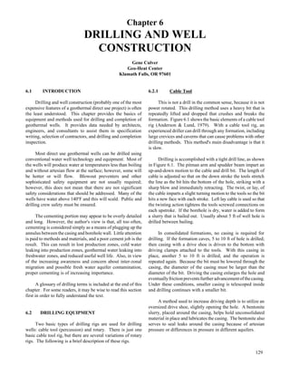
  • 5. Rotary drive Air discharge with drill cuttings Double-wall drill pipe Swivel Air Hammer sub Air to actuate hammer and remove cuttings Interchange sub Hammer Button bit When drilling unconsolidated formations, the bit fits inside the casing and the drive shoe shaves the formation during driving. Casing can be driven ahead of the bit which drills out the plug; or the bit can drill ahead of the casing, then be pulled back into the casing and casing driven; or the casing is driven just behind the bit at the same rate as bit penetration. Friction between the casing and borehole limits the amount of casing, of a given size, that can be driven. When it is necessary to set casing through a hard or well consolidated formation, an under-reaming bit, usually a downhole hammer, can be used. Because the casing seals off all but the near bottom formation cuttings, sampling is excellent, lost circulation problems are eliminated, and accurate estimates of water production can be obtained. The requirement for pulling the casing before cement-ing (similar to drill and drive cable tool) and the additional noise of the casing driver are the main disadvantages. Dual Tube Reverse Circulation This method is probably not applicable for most production wells because the largest outside tube diameter available is 9 5/8 in. It is, however, an excellent test well or pilot hole drilling method because it provides excellent cutting sampling and flow estimates. The drill pipe is double wall, usually flush jointed. Drilling fluid can be air, foam or light bentonite, or polymer muds. Fluid is circulated down between the pipe walls, through a bit sub, inward across the bit, picking up cuttings, and up through the inner pipe. The bit is normally one nominal size large than the outer pipe; therefore, a good seal between the pipe and well wall is obtained (Figure 6.4). Figure 6.4 Dual tube reverse circulation drilling (Johnson Division). When using a tricone bit, the distance between the bit and the bottom of the outer pipe is only a few inches, so samples are very representative of the formation actually being drilled. When using a downhole hammer, air flows through a hammer sub and the hammer, out the bottom of the hammer and up around the hammer to the sub where it is channeled to the inner pipe. The formation sample will be primarily from the hammer face, but the water samples could come from anywhere along the length of the hammer (Figure 6.5). Figure 6.5 Use of an interchange sub (Drilling Service Company). The cross-over channel in the interchange sub mounted on top of the hammer permits the cuttings to enter the inner casing. Drilling depth, limited by friction between the well wall and outer casing, can be approximately 2,000 ft in consolidated formations. 6.2.4 Core Drilling Core drilling is basically an exploration method. This technique is widely used in mineral exploration, civil works foundation investigation, and wells for scientific investigation. It is also used for geothermal test and/or temperature gradient well drilling where accurate and complete lithology are required. It would rarely be used for production wells since the largest standard hole diameter is 4.828 in. and the method is very expensive. Core drilling equipment is designated by a letter size. Table 6.1 shows dimensions of core, hole, and drill rods for commonly used letter sizes (B, N, H, and P). 133
  • 6. Table 6.1 Common Core Sizes Normally Use for Geothermal Drilling ______________________________________________ Drilling Equipment Designation B N H P Core size 1.432 1.875 2.500 3.345 Hole size 2.360 3.040 3.850 4.828 Drill rod ID 1.813 2.375 3.063 4.063 Drill rod OD 2.188 2.750 3.500 4.625 ______________________________________________ There are several core drilling methods, but the usual method used in geothermal work is known as the wire line method. In this procedure, hollow drag-type bits with an ID of the core sizes and OD of the hole sizes, as shown in Table 6.1, are rotated by the drill rod. A core barrel (a pipe with grips to hold the core) is lowered inside the rod by means of a cable, and over the core being cut. When the barrel (usually 10 ft long) is full, it is pulled out and replaced with another. The core is removed from the barrel, laid out in core boxes, labeled, and the barrel is readied for the next trip. The result is a more or less continuous sample of the material drilled in nearly the same form as it existed at depth. Usual practice is to drill 200 to 500 ft using a tricone roller bit, set and cement casing, (and install blowout prevention equipment if required), before starting the coring operation. The core bits (Figure 6.6) are usually faced with a powder metallurgy diamond grit material. Water or thin bentonite drilling fluid is circulated for bit cooling and drill rod lubrication. Surface returns of drilling fluid are desirable, but drilling without returns is practical, because the cuttings are very fine and not as likely to stick the downhole string as in conventional rotary drilling. Fluid circulation rates are low because the annulus is small and drilling fluid is not a major expense. Figure 6.6 Core bits (Tonto Group of Companies). 134 The drilling rigs are small, can be mounted on a single truck, and can be readily moved. Depths to 7,500 ft are possible, usually starting with a large size drill and reducing the size as drilling progresses. A drill rod string and bit can be left in place and a smaller size started through it. When the hole is completed, the drill rod strings are removed and casing installed, or the hole is cemented and abandoned, depending on its purpose. 6.2.5 Directional Drilling Ordinarily, a well is drilled as straight and plumb as reasonably possible, particularly for direct use projects. This makes well completion and pump installation much easier and more economical. Directional drilling is often used in geothermal electrical generation reservoirs where there are economics realized by drilling several wells from one drill pad and steam gathering systems are simplified. To date, the only directional drilling for direct use projects has been to sidetrack junk in a hole, i.e., twisted off drill pipe that cannot be fished out. Directional drilling could be used to intersect a fault for increased production, or to parallel in close proximity to a fault to reduce the possibility of fault movement shearing off a casing. However, the economics of direct use projects usually will not permit the additional expense. Modern controlled directional drilling is accomp-lished by using a downhole motor driven by drilling fluid pumped down the drill string. The motor is attached to the string by a bent sub and non-magnetic sub. The drill string and subs do not rotate. The bent sub is angled one to three degrees and is oriented to guide the drill motor and bit in the desired direction. Periodic surveys using plumb bobs and magnetic compasses with cameras to record their readings allow the directional drilling engineer to plot the course of the well and make changes to direct the hole in the desired direction. New downhole electronics provide continuous monitoring of magnetic signals and the high side, providing the drilling engineer with real time tool orientation and steering capabilities. In order to get around junk in the hole in direct use projects, the old fashioned whipstock or a knuckle joint are more appropriate, if the proper tools can be located. The use of downhole motors has become so common that whipstocks are sometimes in short supply. A whipstock is a long steel wedge-shaped tool that is concave on one side to hold and guide a whipstock drilling assembly. If the hole is not cased, a removable whipstock can be set and a small diameter rat hole drilled 10 to 20 ft beyond the whipstock toe. The whipstock is then removed, the hole reamed, and drilling continued with a full gauge bit and stabilizers to get around the junk.
  • 7. If the hole is cased (usually a permanent whipstock is set, sometimes in a cement plug), diamond or carbide mill bits are used to drill out the side of the casing. Several feet of open hole is required before the standard drill bit is again used. Full size stabilizers maintain hole direction until the junk is by-passed. A knuckle joint is a spring-loaded universal joint located between the drill string and the bit, allowing the bit to drill at an angle with the drill string. The direction cannot be controlled as it can with the whipstock or drilling motor, but this is usually not important when side tracking around junk. Once the initial hole deflection has been established by one of the above methods, the angle can be controlled by the proper selection of stabilizers and subs. To increase the drift angle, a full-size stabilizer is inserted into the string just above the bit and a limber subassembly used. As weight is applied to the bit, the limber sub deflects and the stabilizer has a crowbar effect, increasing the drift (Figure 6.7). Weight Fulcrum effect Figure 6.7 Fulcrum effect (Eastman Whipstock). To maintain hole direction, a full-size stabilizer is used just above the bit, a stiff drill collar, and another full-size stabilizer. The stiffness of the assembly and close fit with the hole resist curving and the bit moves forward along a straight but inclined line (Figure 6.8). The longer the stabilizers and stiffer the collar, the better the hole direction is maintained. To decrease the angle, the stabilizer at the bottom is removed and a more limber collar is used. The upper stabilizers hold the top of the collar away from the low side of the hole and gravity acts on the limber collar and bit to bring the hole back to vertical (Figure 6.9). Figure 6.8 Use of a stabilizer (Eastman Whipstock). By selecting the size and location of the stabilizers, stiffness of the collars and carefully controlling drilling weight, the rate of hole drift, either increasing or decreasing, can be controlled. Figure 6.9 Bringing drill head to vertical (Eastman Whipstock). 6.3 DRILLING FLUIDS Most low- and moderate-temperature geothermal aquifers will be confined, but wells will usually not flow. Static water levels generally vary from a few tens to a few hundreds of feet below the surface. Many are fault controlled, and very often drilling will be in areas of uplifted or down-thrown subsurface blocks. Depth to the aquifer and production rates can vary substantially over short 135
  • 8. distances, and temperatures sometimes change rather dramatically with small changes in depth. Temperature reversals are often experienced with increasing depth after drilling through an aquifer (see Figure 7.10). In the western U.S. and many other locations throughout the world, drilling is often in fractured and faulted metamorphic and igneous rocks, and production is from weathered or inter-bedded lavas and contacts between lithologic units. Production zones may be only a few feet thick. Because most direct use projects cannot afford extensive geological and geophysical work or test drilling, it is important that all production zones be recognized. The above conditions require careful selection and maintenance of drilling fluids. In many areas, air or foam are the preferred fluids. However, it is recognized that other fluids will be used because of caving hole conditions, for control of downhole pressures, availability and capability of rigs, or preference. Both the engineer and the driller must be aware of the possible consequences of fluid selection and maintenance. All drilling fluids perform three basic functions: 1. Cooling of the drill bit. 2. Removal of cuttings as they are produced at the drilling face. 3. Transporting cuttings up the hole. Depending on local conditions, most drilling fluids (usually mud) may also: 1. Stabilize the hole to prevent cave-ins. 2. Minimize formation fluid migration into the hole. 3. Minimize fluid losses to the formation. 4. Lubricate mud pump, bit and the annulus between the drill string and the hole. 5. Reduce drill string corrosion. 6. Suspend cuttings during periods of non-circulation. 7. Assist in collection and interpretation of samples and borehole geophysical logs. 8. Release cuttings in the mud tank or pit. Ideally, fluids used in most direct use drilling should also permit immediate and accurate detection of geothermal fluids, temperature changes, and production zone lithology. Unfortunately, fluid characteristics allowing these to be accomplished are in almost direct contradiction to characteristics required to accomplish most of the other requirements listed above. 136 Drilling fluids fall into one of three general classes: water based, air based, or oil based. Oil-based fluids may be used in petroleum drilling, but are not appropriate for low-to- moderate temperature geothermal drilling because of the danger of contamination of aquifers. Mists fall into the air classification because most of the characteristics are similar, and water into the mud class because recirculated water is very thin mud containing suspended particles of drilled formations. Mud is probably the most common drilling fluid and, while useful for the purposes listed above, presents many of the problems encountered in geothermal drilling. 6.3.1 Lost Circulation Lost circulation is the loss of drilling fluid from the borehole through cracks, crevices, or porous formations. It can be partial or complete, depending on the conditions. Lost circulation is sometimes referred to as lost returns, either partial or complete, because part or all of the fluid fails to return to the surface. When circulation is lost, the drilling fluid is not performing one of its major functions, that of transporting the cuttings up the hole where they can be released in the mud tank or pit. If the cuttings are not removed from the hole, they will pack around the drill string above the bit, resulting in stuck pipe and possible loss of the bit, collars, part of the string and perhaps, the hole. If the formation has large cracks or crevices, the fluid may carry the cuttings into the formation and away where they cannot pack around the drill string, but there is no way of being assured that this is the case. Drilling without circulation is known as drilling blind. Complete loss of circulation usually results in the fluid level dropping to considerably below the surface with the resultant complete or partial loss of fluid pressure stabilizing the hole walls. This can result in cave-ins, another cause of stuck pipe. Lost circulation is probably the most important problem encountered in drilling. It results in: (1) loss of expensive fluid components, (2) loss of drilling time, (3) use of potentially expensive lost circulation materials to keep the losses from plugging possible production zones, and (4) leads to cementing problems, in addition to possible loss of equipment in the hole, as noted above. Despite the severity of the problems, most experts agree that probably one-half the lost circulation problems can be avoided and many are driller induced. Proper planning and rig operation are important. Some of the techniques involved in proper planning and operation are listed below: 1. Insofar as possible, use nearby well logs and geologic information, and carefully plan the hole and the casing program.
  • 9. 2. Treat the well bore gently. Raise and lower drill strings and casing slowly. Do not spud or swab. Start fluid pumps at slow rates and increase slowly. Maintain fluid velocity in the annulus at the lowest rate to assure cuttings removal. Do not drill so fast as to overload the annulus with cuttings. 3. Make frequent measurements of mud properties to maintain minimum weight, viscosity, and filtration. 6.3.2 Drilling Muds Modern drilling muds are primarily mixtures of western bentonite (sodium montmorillonite) and water. Organic polymers, dispersants, wetting agents, weighting materials, thinners and lubricants are added to modify properties to meet changing hole conditions or counteract changes previously made by the driller. When bentonite is added to water, several changes in physical properties take place. Some of the more important are increases in density and viscosity; and gelation, lubricity, and filtration properties are added. As the mud is used, there are changes in suspended solids and sometimes chemical changes that affect physical properties. Some of the mud properties can be relatively easily measured and related to performance. Density Mud density or mud weight is measured by a simple balance beam or mud balance and is usually expressed in pounds per gallon (lb/gal). As density is increased, the buoyant effect increases carrying capacity for cuttings but decreases settling rate in the mud pit. Increased density increases borehole pressure and the ability to prevent caving and flow into the hole. Conversely, it increases the tendency to flow out of the hole and into the formation, and therefore, may result in increased loss of circulation. In fact, lost circulation can sometimes be regained by the simple expedient of reducing density. The generally recommended maximum density is 9 lb/gal; less is highly desirable. Density can be increased by the addition of barite without unduly altering other mud properties. Solids such as sand, fine cuttings, silt, etc., increase density and are undesirable because they increase pump and other components' wear rate, retard drilling rate, form a thick filter cake, and increase power requirements of the mud pump. Hydrostatic pressure can be calculated by: P = 0.052 ed where P = hydrostatic pressure (psi) e = fluid density (lb/gal) d = depth (ft). Example: If geothermal water at 200oF (density = 8.049 lb/gal), which if unrestricted would rise to 300 ft below the surface, is encountered at 1,500 ft using 9 lb mud, the pressure keeping geothermal water out of the hole and tending to force mud into the formation is the pressure caused by mud minus the pressure caused by water giving: P = (0.052 x 9.000 lb/gal x 1,500 ft) -(0.052 x 8.049 lb/gal x 1,200 ft) P = 200 psi. This applies only when mud is not circulating. When circulating, the pressure would be higher, depending on viscosity, borehole and drill string diameters, filter cake thickness, etc. Rapidly raising or lowering the drill string during tripping or spudding significantly changes downhole pressures. Pressure will be increased in the direction of movement, possibly causing mud invasion into the forma-tion and lost circulation or both. Rapidly raising the string creates a swabbing effect and lower pressure below the string. In high temperature and/or pressure situations, this can induce a well to flow or flash, resulting in a possible blowout. Although drilling with pure water eliminates the possibility of mud damage to the formation, the pressure difference is still approximately 148 psi, which effectively reduces the possibility of detecting geothermal water when the producing formation is encountered. Viscosity Mud viscosity is primarily a measure of its ability to carry cuttings up the hole, drop them in the mud pit, and to form a gel. It is changed by varying the amounts of bentonite and water or by adding polymers to thicken or phosphates to thin. There is no simple, accurate and economical method of field measurement, but apparent or funnel viscosity is obtained by measuring the time it takes a measured amount of mud, usually one quart, to flow through a standard Marsh funnel. Water has a funnel viscosity of 26 seconds/quart (s/qt) at 70oF. A good drilling mud has a funnel viscosity of 32 to 38 s/qt. Funnel viscosity is affected by density and the type of suspended solids. Well rounded sand can decrease funnel viscosity by 10 s or more but the true viscosity changes very little. Funnel viscosity means very little by itself, but in combination with other mud measurements can be useful to the experienced driller. Sand Content Sand content affects mud density and apparent viscosity, equipment wear (especially mud pumps), bit life, drilling rate and formation damage. Sand content is measured by carefully washing a measured volume of mud 137
  • 10. on a 200 mesh screen. The material held on the screen is poured into a cone shaped graduated container. The desired maximum limit is 2% by volume. Sand content can be controlled by using low viscosity mud, multiple pits and tanks of adequate volume designed to eliminate short circuit flows and the use of de-sanders. Mud pits or tanks should have a volume of at least three or four times the finished hole volume and the pump intake should be suspended near the surface. Because a high sand content increases density, it de-creases the likelihood of detecting an under-pressured geo-thermal resource. For the driller, the investment in mater-ials and time to regularly measure sand content will soon repay itself in reduced wear of mud pumps, swivels, etc. Filter Cake When the mud is in the borehole, pressure in the annulus tends to force it into any porous formation. Clay platelets build up on the formation and reduce fluid loss. This buildup of clay is called the filter cake. Some water filters through the cake and is water loss while loss of both clay (and other constituents) and water is mud loss. It is desirable to maintain a thin, easily removed filter cake while minimizing water loss and maintaining circulation. Water loss and filter cake thickness are measured using a standard API filter press. Filter paper is supported in a mud filled standard cell and 100 psi is applied and maintained by a pressurized gas cylinder. The amount of water passing through the filter paper in 30 minutes is measured and the buildup of filter cake on the paper measured to 1/32 in. Desirable properties are 15 cm3/30 min and 2/32 in. thickness. Gelling One of the properties of a bentonite and water mix-ture, thixotropy, is its ability to gel. The mixture is fluid while being stirred, but stiffens after standing. When stirred again, it becomes a fluid. This property helps suspend drill cuttings during non-circulation periods. Gel strength yield point and time are very seldom measured by small rig operators but are related to funnel viscosity readings taking other factors into consideration. The ability to gel is the property that makes mud highly undesirable while drilling in many geothermal production zones. When circulation is lost or reduced, mud flows into the fractured or unconsolidated formation. As long as flow is maintained, the mud acts like a viscous fluid and will continue to flow until the frictional resistance equals the pressure difference between the annulus and the formation. In conventional drilling, the mud also carries small cuttings into the formation. Cuttings may partially fill the voids, increasing resistance to flow, and circulation may 138 be regained or lost circulation materials may be added and circulation regained. If circulation is regained, mud flow in the formation stops and, unless sufficiently diluted by formation water, the mud gels. Gelling is progressive; that is, gel strength increases with time and, in the more com-monly used bentonite muds, increases with temperature. Gelling is one method of stopping lost circulation. Viscosity is increased by adding bentonite, sometimes to the point where the pump will hardly pump it. Some of the thick mud is pumped, filling the formation, then the bit pulled back a safe distance and the hole allowed to set for several hours to a day. Continued drilling with very light mud, slow rotation and slow mud pump speed will sometimes permit finishing the hole or drilling to where casing can be set. In either case, if the zone was a potential geothermal producer, it may be lost forever. Once the gel forms at some distance from the bore it is difficult, if not impossible, to remove by ordinary development methods. Mixtures of hydrochloric and hydro-fluoric acids, and phosphate thinners, with vigorous swab-bing at about 4 hr intervals are sometimes effective but expensive. There is always some element of risk in acidizing because the acid doesn't always go where it is needed. Lost Circulation Materials Lost circulation materials (LCM) are materials that bridge across openings in the formation, providing a foundation for the buildup of filter cake. Almost every conceivable material has been used including sawdust, alfalfa pellets, chicken feathers, ground walnut shells, cotton seed hulls, hog hair, and many others. There are also a variety of gelling agents or mixtures that form stiff gels when mixed with water or salt water. A bentonite and diesel oil slurry, when mixed with water, forms a thick putty-like mass. In the trade, this is often referred to as gunk. Flo-Chek (Halliburton Services, undated) forms a similar thick gel when mixed with salt water. Many of the LCMs are organic and may have the potential to promote undesired organic growth or degrade water quality or both. Because in many areas, low-to-moderate temperature geothermal fluid has the potential to mix with underground fresh water supplies, the use of these material is prohibited. In areas where the geothermal fluid is bottled as mineral water, the bottlers would very emphatically oppose their use. Inorganic materials, such as mica flakes and gilsonite, or inert materials such as some of the plastics can be used, although they are not always as effective. The best materials will be a mixture of flake and fiber of various sizes in order to effectively bridge openings in the formation.
  • 11. Recognizing Geothermal Zones Geophysical logging and interpretation can detect zones that may be low-temperature geothermal production zones. A good estimate of the geology and hydrology conditions by a qualified geologist is always helpful for log interpretation in an unknown or exploration area. However, logging is expensive and most direct use applications cannot afford frequent logging and interpretation. Monitoring mud entering and return temperatures can sometimes indicate higher temperature zones. This can indicate approaching a production zone. When the produc-tion zone is encountered, circulation will probably be lost or reduced. However, increases in temperature are frequently masked by cold strata above the drilling level, cooling the mud as it rises up the annulus. The effectiveness of the technique depends on the formation temperatures, drilling rate versus downhole temperature, temperature measure-ment frequency, and weather conditions (more difficult in hot weather with low formation temperatures). Continuous monitoring and recording is best, but few water well drillers have the recording equipment. At the minimum, tempera-tures should be recorded each 30 minutes or 20 feet of drilling. Temperature logging between trips has not been very indicative of downhole conditions. Recently circulated drilling fluid produces a nearly isothermal temperature log. If drilling is stopped regularly overnight, temperature logging before circulation each day has been indicative of rock temperature trends but is usually several degrees lower than if the hole sits several days to a week. In summary, recognizing and evaluating a low temperature, under-pressured geothermal aquifer while drilling with mud is next to impossible. About the best that can be done is to drill to a lost circulation zone that should be hot, stop circulating mud immediately, clean the hole and air lift or test pump. If a geothermal aquifer is confirmed, drilling can be continued with air, pure water or cable tool. An over-pressured aquifer, in flowing resources, is more easily detected by increased mud pit level and higher temperatures. 6.3.3 Polymer Fluids There is a wide variety of polymers used in water well and petroleum drilling, both natural and synthetic. Synthetic polymers may imitate natural polymers or be totally different; and they may be either organic or inorganic. Many of the natural polymers are biodegradable. Others are easily broken down by oxidizers such as weak acids. Polymers have essentially no gel strength but provide high viscosity; therefore, they carry cuttings up the hole and drop them in the mud pit quickly. Because they are readily broken down and have no gel strength, they have been suggested for low-temperature geothermal wells to eliminate some of the problems with bentonite. Some of the polymers are temperature sensitive; they lose viscosity quickly at temperatures of approximately 100oF and therefore, are not suitable. However, others are stable to 300oF. Because of the potential for pollution, some states have prohibited or restricted use of some, if not most, organic material in domestic water wells. Synthetic duplicates would also be included. Because low-temperature geothermal wells are treated as groundwater wells in many states, and low-temperature geothermal aquifers may be hydraulically connected to drinking water aquifers, use of polymers may be restricted. Geothermal fluids contain chemicals and dissolved gases that may react with polymers, especially at elevated temperatures. Reactions could either break the long molecules reducing viscosity, or cross link molecules forming a thick gel. Before using any polymer, it would be wise to consult the manufacturer giving him the expected temperature and water chemistry and, if possible, testing the polymer with a sample of the geothermal fluid from another well or spring. 6.3.4 Air-Based Fluids Drilling with dry air is the simplest air drilling technique. Obviously, when water is encountered in the hole, its no longer dry and must be converted to mist or foam. In general, the lifting capacity of air is proportional to its density and to the square of its annular velocity. Velocities of 3,000 to 5,000 ft/min are usually required (Driscoll, 1987). For a given hole and drill pipe size, air volume requirements are directly related to depth. As the hole depth increases, expansion at the bit is less (therefore, velocity is less) because of the increased weight of cuttings supported and pressure buildup because of friction. Excessive air velocity can lead to erosion of softer formations which, in turn, requires more air to maintain adequate velocities in the enlarged annular space. Excessive air pressure can cause air loss to the formation. Air loss, like lost circulation when drilling with water-based fluids, results in cuttings not being lifted and the danger of sticking tools. Unconsolidated formations and, to a large extent, excessive cold water invasion from overlying aquifers can be controlled with drill and drive methods. Small amounts of formation water, when mixed with cuttings dust, particularly shales, can cause mud rings to form on the drill pipe and hole wall. Below these rings, pressure buildup reduces velocities and can cause air losses to the formation. Air systems provide little support to unconsolidated formations and there is danger from caving, possibly resulting in stuck tools. Consolidated formations, where air drilling is at its best, do not present that danger. Air mist drilling is the result of adding small amounts of water at the surface. Wetting agents are often added to help remove mud rings and control dust. Air volume requirements are increased because of the increased density 139
  • 12. Surfactant Metering pump Compressor Highest T Highest P Lowest v Blooie line discharge Highest v atmospheric P Control valve Water source Casing seal Clearing assist line Surface casing Annulus Drill rods Decreasing P Decreasing T Decreasing P Increasing v Stabilizer Bit Rapid decrease in P rapid increase in v rapid decrease in T of the air column, resulting in increased pressure at the bottom of the hole. Air mist techniques can be used satisfactorily as long as only small amounts of water (15 to 25 gpm) enter from the formation (Driscoll, 1987). Foam drilling is used when larger amounts of water enter the hole. Usually foam is thought of as a small amount of air in a large amount of water. Drilling foam, however, is a small amount of water with a large amount of air, similar to the soap on top of a dish pan. Drilling foam is made by injecting water and additive into an air stream. Foam drilling occurs when the liquid volume fraction (LVF) is <-2.5%. LVFs >2.5% are usually termed aerated fluids. Stable foams are produced by adding surfactants. Polymers and clays may be added to increase viscosity and density. The addition of surfactants provides: 1. Ability to lift large volumes of water. 2. Reduced air volume requirements. 3. Greater solids carrying capacity. 4. Reduced erosion of poorly consolidated formations. Annular velocities as low as 50 to 100 ft/min can be used with stiff foams made with polymers (3 to 6 lb/100 gal) or bentonite (30 to 50 lb/100 gal) and 1 to 2% surfactant. Bentonite should not be used with a downhole hammer, but other types of foam can be used. Wet foams, which may require annulus velocities up to 1,000 ft/min, are made with 0.25% surfactant and no other additives. Surfactant and other additives are mixed in a large tank and injected into the air stream by a metering pump. Maximum lift is obtained using 2% liquid volume fraction (2% of the free air volume) (Driscoll, 1987). Being a compressible fluid, air follows the ideal gas laws. This holds for all air-based drilling, dry air, mists and foams, with appropriate modifications for any additions to the air. Pressure and temperature are high and the volume is small in air feed lines and drill pipe. At the bit, expansion occurs with a drop in temperature and pressure unless downhole temperature is high, in which case expansion is further increased. Expansion occurs until pressure at the bit equals pressure caused by resistance to flow, plus any cuttings and water load. When using stiff foams, considerable expansion occurs all the way up the annulus. Figure 6.10 shows how the temperature, pressure and volume change during drilling. a. Basic components of an operating air rotary circulation system showing the pressure and volume conditions in the drilling fluid at various sites. Greatest pressure and volume changes generally occur at the bit, which is the most critical point in an air drilling-fluid system. 140 Figure 6.10 P r e s s u r e a n d v o l u m e relationships during drilling (Driscoll, 1987). b. P = Pressure, T = Temperature, v = Volume. Compared to water-based fluids, air-based fluids have the following advantages: 1. Higher penetration rates, especially in hard rock. 2. Easy detection of aquifers and estimation of potential flow rates. 3. Reduced formation damage. 4. Longer bit life. 5. No water (or very little) required for drilling. 6. Usually better formation samples. The major disadvantages of air are associated with the advantage that all air systems bring the water to the surface. Although this enables the detection of production zones, it presents the problem of disposal of the fluids and the dangers associated with hot water. If a flow of 500 gpm is encountered and drilling is continued for 12 hours in an attempt to get additional flow, the fluid produced will be 1.1 acre-ft. If the water is hot, near or above boiling downhole for example, and is high in dissolved solids, disposing of it can be a major problem in some locations.
  • 13. 0% 5% 10% 0% 15% 20% 25% 5% 10% 15% 20% 25% -30 30 60 90 120 190 210 230 250 270 290 0 200 300 Temperature (0F) 500 600 500 1000 1500 2000 2500 3000 3500 4000 4500 5000 5500 6000 400 Water at 140oF or above will scald. If temperature near or above this are anticipated, appropriate equipment, i.e., rotating head, banjo box, blooie line, safety apparel, fencing, etc., must be used. If water is above the boiling point at the drill site altitude, the air lift may reduce the pressure above the water to the point where flashing will occur (Figure 6.11). Flashing will often continue unaided. This is why blowout prevention equipment is required when elevated tempera-tures are, or will possibly be, encountered. The rotating head constrains the steam and air; steam and cuttings flow out through the banjo box and blooie line. Other disadvant-ages of air drilling include: 1. Higher cost for equipment and fuel costs for driving compressors. 2. Dust. 3. Noise of compressors and blooie exhaust. 6.3.5 Plumbness and Alignment Any well drilled more than a few tens of feet is probably not perfectly plumb or straight. Some misalign-ment is permissible; but, lineshaft pump life can be reduced if the well is overly crooked because it places extra loads on the column bearings. Straightness is more important than plumbness. There are many ways of checking geometry with fairly sophisticated logging tools that check deviation and compass direction. Few drillers have these instruments and the cost will be more than many direct-use projects can afford. Simpler, more economic methods are usually specified. One method of checking well geometry is to use a rigid pipe dummy two casing lengths (usually 40 ft long), with an OD ½ in. smaller than the casing in the section to be checked; assuming that if the dummy passes, the pump will pass and operate satisfactorily. A well with a deep pump setting could have an S curve that would allow the dummy to pass but bind a pump column and cause early bearing failures. Another method is to use a plumb bob and line. The bob can be anything heavy enough to keep the line taut, 1/4 in. smaller in diameter than the inside of the casing and longer than its diameter. The bob is usually an adjustable spring steel wire cage. If the bob is suspended from a pulley above the casing top and the line comes off the pulley exactly over the center, the deviation at any depth can be calculated from: Figure 6.11 Boiling-point curves for H2O liquid (in wt percent) and for brine of constant composition NaCl. The insert expands the relations between 194o and 300oF. The temperature at 0 ft for each curve is the boiling point for the liquid at 1.013 bars (1.0 atm) load pressure which is equivalent to the atmospheric pressure at sea level. 141
  • 14. Minimum of cage “h” “D” “H” = distance top of cage to top of casing Pulley “X” formula for well deviation x = D(H + h)/h CL where X = deviation at given depth (in.) D = distance the line moves from the center of the casing (in.) H = distance from casing top to cage (ft) h = distance from center of pulley to casing top (ft). If the pulley is exactly 10 ft above the casing and readings are taken at 10 ft increments, the calculations are simplified. Both direction and total deviation can be plotted on a scaled deviation plot and an outline of the casing drawn. After plotting the casing, a straight line is drawn from the casing top to the depth where alignment is to be maintained. The casing should not be closer to the plotted center line than the maximum amounts shown in Figure 6.12. Figure 6.12 Plumbness and alignment (Roscoe Moss Company). a. Minimum amount (as shown above): 8" for 24" ID well casing 7" for 20" ID well casing 6" for 18" ID well casing 5" for 16" ID well casing 4" for 14" ID well casing 3" for 12" ID well casing 2" for 10" ID well casing 142 The usual standard for plumbness allows 6 in. out of plumb for every 100 ft of well depth. Some engineers feel that 6 in./100 ft is excessive and allow only 3 in./100 ft (Roscoe Moss Co., 1985). The proposed 15th edition of the Hydraulics Institute's Standard for Well Straightness states "shall not deviate more than 1 in./100 ft and be without double bend" (Cherry, 1987). Table 6.2 gives relative drilling rates of seven drilling methods in various formations. Rates were modified somewhat from Driscoll (1987) after discussions with experienced geothermal direct use drillers. 6.4 WELL DESIGN Well design involves specifying well depth, casing diameters, materials, thickness, lengths and pump setting. Once these are determined, other parameters such as wellbore diameter, completion methods, procedures, and perhaps, drilling methods can be decided. An initial design must be prepared in order to write specifications and obtain a bid; but, probably more often than not, the design changes as actual hole conditions become known. Some require-ments may be specified by state, federal or local agencies. Other factors may be partially or wholly determined by local practices and equipment availability. In many cases, it is prudent to hire a qualified geologist to thoroughly review well logs and published geologic information before the initial design is made, and to interpret cuttings and logs as the well is drilled. There are often critical decisions that must be made during drilling. Having a geologist on-site to help in decision-making can help make drilling proceed smoothly and efficiently. Most direct use wells consist of three main parts: pump housing or surface casing, the inlet portion, and the production casing between them. Flowing artesian wells do not require a pump housing, if flow is sufficient for the intended use. Depth is usually determined by that required to obtain sufficient flow or temperature, or both, for the intended use. The controlling factors are depth to aquifer, thickness of the aquifer, transmissivity of the aquifer, and flow requirements. As noted earlier, the first three may be estimated from nearby wells; but in fractured and faulted areas, there may be considerable differences in depth to geothermal aquifers and flow rates in adjacent wells. Many direct use wells have temperature reversals and get cooler with increased depth, once the aquifer has been fully penetrated. In pumped wells, the final pump setting is determined from well testing, usually with a portable pump. These data should provide water levels for various pumping rates, and perhaps, estimates of long-term drawdown, depending on
  • 15. Table 6.2 Relative Drilling Rate in Various Formations ________________________________________________________________________________________________ Alluvial Fans, Glacial Drift Sandstone Basalt-Highly Fractured- Granite & Other Loose Sand with Loose Clay, Silt Cemented Limestone Basalt Lost Circulation Non-Fractured Gravel Boulders Shale Conglomerates Limestone Cavernous Layers Zones Metamorphics Cable tool Slow Slow-difficult Slow, medium Slow Slow Medium Slow to Slow, sometimes difficult Slow In brittle shale medium Direct rotary (air) (------------------NOT RECOMMENDED-------------) Fast Fast Slow, Fast Medium Med. to fast Direct rotary (fluid) Fast Impossible to Fast Med. to fast Med. to Slow to Slow to Slow to impossible Slow to medium very slow fast impossible medium Air hammer (------------------NOT RECOMMENDED-------------) Harder types Very fast Fast Fast Medium to fast Fast Fast Reverse rotary Fast Medium Fast Med. to fast Medium Slow to Slow to Slow to impossible Slow to medium impossible medium Drill thru-casing driver Very fast Medium to Fast (-------------------------------------------------------------NOT APPLICABLE---------------------------------------------------------) difficult Dual wall Very fast Medium Fast Med. to fast Med. to Fast Fast Medium to fast Slow to medium fast ________________________________________________________________________________________________ the degree of sophistication of the test. Deep and/or high production wells for district heating or industrial uses should have a good testing program unless the reservoir is well known. See Chapter 7, Reservoir Engineering, for test program descriptions. Space heating for residential or light commercial applications probably cannot justify extensive testing but, if they are in known areas, expected pump settings can be obtained from nearby wells. Air lift or bailing with the drilling rig can provide information on the expected flow rates and drawdowns. Consideration should also be given to possible long-term water level declines, reduction in well efficiency over its life because of scaling and possible increased production requirements at some later date. The pump itself is relatively easy to set deeper; well work over to lower the surface casing is much more expensive and sometimes impossible. Surface casing size is set by the pump bowl diameter. Pumping rate from a given pump diameter can vary con-siderably and pump suppliers should be consulted before drilling to determine the least life-cycle cost for the pump and well. Larger diameter, low-speed lineshaft pumps are usually more efficient and require less maintenance than smaller, high-speed pumps with the same flow and head. However, where settings are deep and drilling difficult, the cost of a larger diameter well may not justify the savings in maintenance and pumping power. Surface casing diameter should be two nominal pipe sizes larger than the pump bowls. This permits easy instal-lation and allows for some well deviations. One nominal pipe size larger is permissible, but not recommended. In case of necessity, the outside diameter of pump bowls can be trimmed a small amount. Table 6.3 is based on pump data from several manufacturers, for both lineshaft and submersible, and provides a general idea of the diameter required for given pumping rates. Because many geothermal aquifers are confined, they will have high static (close to the ground surface) and pumping levels. In this situation, casing and/or bore sizes, or both, can be reduced below the surface casing pump chamber. Many times, at least a portion of the well, between the pump chamber and well bottom, will be in rock and can be left open hole if state regulations permit. In shallow wells, the surface casing is often extended into rock above the aquifer and cemented in place with open hole the rest of the way to total depth. This method of completion simplifies grouting. Table 6.3 Surface Casing Diameters ______________________________________________ Nominal Pump Nominal Surface Production Rate Diameter Casing Diameter (gpm) (in.) (in.) <100 4 6 100 to 175 5 8 175 to 350 6 10 350 to 700 8 12 700 to 1,000 10 14 1,000 to 1,600 12 16 1,600 to 3,000 14 18 ______________________________________________ In deeper wells, it may be necessary or economical to install one or more casing strings of successively smaller diameters such as when drilling and driving when the casing cannot be driven further. A similar situation occurs when a slotted liner or screen is telescoped through the casing. In water well drilling it is not uncommon to seal the casing/ screen overlap with a lead packer to facilitate screen removal and replacement. Because many geothermal fluids 143
  • 16. will leach lead (see Chapter 8), the water chemistry should be checked if the use of lead is considered. Cement should always be used at casing overlaps. If removal of the slotted liner or screen is anticipated, a high-temperature elastomer seal can be used. Most states regulate the length and annulus space for casing overlap. In the case of water wells and, in some states, low-temperature geothermal wells, the required overlap may be <10 ft. Because sulfate ions, present in most geothermal fluids, attack cements, the length of overlap should be increased to a minimum of 20 ft and the use of high sulfate resistant cement considered, if the sulfate concentration is high. Most states require a minimum of 50 ft overlap in geothermal wells, but those requirements were usually written with high-temperature geothermal fluid in mind. The length of overlap required by regulations may depend on how the well is classified, and not necessarily reflect the best design. Most agencies will permit variances to obtain the best design for the particular situation. The minimum diameter of any open hole or casing string should be selected so that fluid velocities at maximum pumping rates are <5 ft/s. For wells that flow at the surface, velocity (therefore, friction losses that reduce flow) might be lowered by increasing the diameter to obtain greater flows. The additional well costs should be balanced against pumping costs. The diameter of the inlet portion at the bottom of the well should be chosen to accept the water available from the aquifer. Equations in Chapter 7, based on Darcy's basic flow equation, show that productivity is determined to a much greater extent by permeability than by diameter. For identical conditions of permeability, drawdown and radius of influence, doubling the wellbore diameter increases production approximately 10% in an unconfined aquifer and only approximately 7% in a confined aquifer. When a slotted liner or screen is used, the open area of the liner or screen may be the limiting factor (Figure 6.13). Open areas of continuous slot screens typically range from approximately 16% to 50% and slotted pipe approxi-mately 1% to 12%. Therefore, when a screen or slotted liner is required and the thickness of the aquifer limits the length, it may be necessary to increase the diameter in order to utilize all the water the aquifer will provide. Velocity through the open area of the screen or liner should be 0.10 to 0.25 ft/s (Campbell, 1973). Well screen and filter pack are used to prevent sand and fines from entering the well and becoming a sand pumper. Screen openings are small (0.006 to 0.150 in.) and the filter pack is clean graded sand selected to hold back fines from the aquifer, yet not pass through the screen. Selection of the filter pack size and gradation requires sieve analysis of the producing formation and careful selection of 144 Figure 6.13 Slotted liner and screen (Johnson Division, 1966). filter material size. Because very few geothermal wells are screened, the methods will not be covered here. Methods and information are contained in Driscoll, 1987. Formation stabilizer is coarser material (1/8 to 5/16 in. gravel) used to prevent sloughing of borehole walls in the production zone. Slotted liner with openings ranging from 0.120 to 0.250 in. supports the stabilizer material. Many geothermal wells require formation stabilizers. The term gravel pack is often used for both filter pack and formation stabilizer. Placement of filter pack is critical because it contains several selected sizes of material, which tend to separate if just poured down the annulus. Filter pack is carefully placed through a tremie pipe. Formation stabilizer, on the other hand, is usually screened to obtain uniform size and can be poured down the annulus. When cementing is required above the stabilizer or filter pack, 3 to 5 ft of sand is poured or tremied in to prevent cement from entering the stabilizer material. 6.5 CASING MATERIALS Casing materials, minimum thickness for various diameters, maximum depth for various diameters and ASTM or API standards are specified by some states, but may vary from state to state. Local and state regulations must be checked to assure that the well design meets the applicable codes. Casing materials for low-to-moderate temperature geothermal wells include thermoplastics, fiberglass and steel. Concrete and asbestos cement casings are also used in water well construction and may be suitable for groundwater heat pump applications. Steel is by far the most common. Properties of casing materials are given in Table 6.4.
  • 17. Table 6.4 Comparison of Well Casing Materials ________________________________________________________________________________________________ Material Fiberglass Asbestos Low-Carbon Type 304 ABS PVC Epoxy Cement Steel Stainless Steel Specific gravity 1.04 2.40 1.89 1.85 7.85 8.0 Tensile strength (psi) 4,500 8,000 16,750 3,000 35,000 ylda 30,000 ylda 60,000 60,000 ultimate ultimate Tensile modulus (106 psi) .30 .41 2.30 3.00 30.00 29.00 Impact strength (ft·lb/in.) 6.0 1.0 20.0 1.0 b a Upper temperature limits (oF) 180 140 200c 250 800 to 1,000 800 to 1,000 Thermal expansion (10-6 in./in. oF) 55 30 8.5 4.5 6.6 10.1 Heat transfer (Btu in./h ft2 oF) 1.35 1.10 2.30 3.56 333.0 96.0 Water absorption (wt %/24 h) 0.30 0.05 0.20 2.0 Nil Nil __________________________________ a. Yield strength is the tensile stress required to produce a total elongation of 0.5% of the gauge length as determined by an extension meter. Expressed in psi. b. Because testing methods for steel and other materials are not the same and the results are not comparable, the impact strength values for steel are not shown. In any event, the actual impact strength of steel is so high relative to the demands of water well work that it can be ignored in design considerations. c. May be higher with special formulations. ________________________________________________________________________________________________ Steel casing is pipe manufactured to ASTM standards A-53 and A-120, or line pipe manufactured to API standards 5L, 5LX (high strength), and 5A. Pipe is available with either threaded and coupled or beveled ends for welding. Most low-to- moderate temperature casing is welded because this is the most common practice in water well construction. Welding should be to American Welding Society standards, fully penetrating multiple pass welds. In oil and gas producing areas, threaded and coupled pipe may be more readily available in sizes below approximately 8 in. Welded pipe is usually used, since it is less costly and welded joints are stronger than threaded and coupled joints for the same pipe thickness. Most direct use wells are shallow enough that casing tensile and compressive strengths are not a problem. Collapse pressure is greatest during cementing and collapse stresses will probably be the critical design factor. Table 6.5 gives physical characteristics of blank steel casing based on the following formulas (Roscoe Moss Co., 1985): The values for collapse pressure in Table 6.5 were determined by: where Pcr = theoretical collapse strength of a perfectly round tube written as: where E = Youngs modulus = 30 x 106 psi M = Poisson's ratio = 0.3 Do = casing OD t = casing wall thickness 145
  • 18. Table 6.5 Physical Characteristics Blank Casing ________________________________________________________________________________________________ Axial Nominal Outside Inside Collapsing Compressive Tensile Diameter Wall Thickness Diameter Diameter Weight Strength Strength Strength _______________________________________________________________________________________________________________________ Inches Inches Inches Inches LB/FT PSI Ft. Water Tons Tons ______________________________________________________________________________________________________________________ 8 1/4 8.625 8.125 22/36 755.54 1745.29 115.11 197.33 10 1/4 10.750 10.250 28/04 461.08 1065.10 144.32 247.40 12 1/4 12.750 12.250 33/38 36.09 707.06 171.81 294.52 14 1/4 14.00 13.500 36/71 242.43 560.02 188.99 323.98 14 5/16 14.00 13.375 45/58 418.68 967.15 235.16 403.13 14 3/8 14.00 13.250 54/57 636.10 1469.39 290.90 481.55 _______________________________________________________________________________________________________________________ e = casing ellipticity = 1% S = yield strength = 35,000 psi Pe = collapse pressure with ellipticity (psi). The values for casing tensile strength set forth in Table 6.4 were determined by: where St = tensile strength = 60,000 psi. The values for casing axial compressive strength were determined by: where S = yield strength = 35,000 psi. Collapse strength is reduced by ellipticity, bending and axial stress, and increased by compressive stress. Ellipticity of 1% is allowed in the ASTM and API standards and taken into account in the above equation. Additional ellipticity caused by rough handling and bending, and axial stresses induced during installation such as in crooked holes, should be allowed for by an appropriate safety factor. If an accurate plot of the well geometry has been made, the additional stresses can be calculated using standard strength of materials calculations. All steel well casing tends to corrode faster in an area above the water line where water vapor and air mix. This is exaggerated in geothermal wells because the higher temperature increases both the amount of water vapor 146 and the distance it moves up the casing. Sealing the top of the casing and any openings such as for air lines and access ports for measuring devices will minimize oxygen intrusion and corrosion. Increasing the wall thickness will increase well life. Unfortunately, there is no good standard practice or rule of thumb for increasing thickness, because temperature and water chemistry vary so widely. Each application should be judged individually. Past experience based on local practice can sometimes help, but often other wells have not been in use long enough to give a good indication of expected life. Thermoplastic well casing standards are covered in ASTM Standard F-480, which includes a method for calculating collapse strength. Care should be exercised when specifying thermoplastic casing for elevated temperatures because collapse strength is reduced drastically. As with any casing, the collapse pressure will be greatest during cementing and the placement method should be chosen so as to equalize pressures inside and out as much as possible. Heat generated during curing of cement grout further increases the temperature that the casing must withstand. Use of thermoplastic pipe is discussed in Chapter 10, which gives strength decreases with rise in temperature. These factors are also applicable for collapse strength reductions. Fiberglass-reinforced epoxy or polyester casings and pipe are produced with many resin formulations and winding procedures that affect the temperature and strength characteristics. At the present time, there is no standards covering all the various resins and construction methods for well casings; however, pressure piping is covered by several standards (see Chapter 10). Pressure piping is available for temperatures up to 300oF. Fiberglass-reinforced casing has several advantages, including excellent corrosion resistance, light weight and high strength-to-weight ratios. It is available with several
  • 19. thread type connections, including threaded and O-ringed, and bell and spigot with locking keys that permit speedy installation. Resin joining of bell and spigot or tapered joint couplings requires considerable time, experienced workmen and heat curing for use at elevated temperature. The major disadvantage of fiberglass is cost, which is higher than steel on a per foot basis. Installed cost may be competitive when using the threaded or keyed couplings. Another disadvantage is that pump housings must be plumb and probably larger diameter to ensure that pump parts do not contact the inside of the casing. Pump vibrations will wear a hole in the inner lining permitting hot water to wick along the fiberglass filaments and lead to separation of filaments and resin. 6.5.1 Centralizers Casing should be run with centralizers or centering guides to assure that all voids are filled and channeling does not occur during cementing. Centralizer spacing depends on hole straightness and clearance between the casing and bore. Plastic casing requires closer spacing than steel casing. Some states regulate the maximum spacing. Centralizers for shallow, straight wells are typically fabricated from 1-1/2 to 2 in. x 1/4 to 5/16 in. steel flat bar, bent and welded to steel casing to provide 1/4 to ½ in. clearance with the well walls. For thermoplastic casing, centralizers are strapped to the casing with stainless steel clamps. Screws should not be used because they are subject to corrosion, leaving holes in the casing. Fiberglass centralizers are available for fiberglass casing. Centralizers used in the petroleum industry (for deep or crooked holes or both) float on the casing and are held in vertical spacing by lock collars (Figure 6.14). This permits the casing to be rotated. Wall scratchers or cleaners attached to the casing clean filter cake from the bore walls, providing better cement bonding to the formation and reduce cement channeling. Figure 6.14 Centralizer. 6.6 GROUTING/CEMENTING 6.6.1 General Grouting and cementing have become synonymous. Grouting may be more technically correct, because grouting is the act of implacing any sealing material. Cement is the usual grouting material for wells, although clays are permissible (in some states) where their location will not permit drying and shrinkage. Cementing is probably the more common terminology in geothermal work. Grout is placed in the annulus between the casing and well walls or between strings of casing of different diameter to prevent mixing and/or contamination of aquifers by undesirable aquifers or surface water. Because its purpose is to protect aquifers, most states have adopted regulations specifying acceptable materials and methods of placing grout. Portland cement is the most common grouting material. ASTM Types I, II, and III are commonly used in water wells. The petroleum industry has developed eight classes of cement to meet the special conditions of deep oil and gas wells. API Classes A, B, and C correspond to Types I, II, and III respectively. The other classifications were devel-oped to permit the use of accelerators, retarders and other additives to meet special requirements. Because the ele-vated temperatures of geothermal wells are similar to oil and gas conditions, many of the materials and techniques used in petroleum industry are applicable. The following information on basic cementing material is provided courtesy of Halliburton Services (undated). 6.6.2 Cement Types and Classifications A basic cementing material is classified as one that, without special additives for weight control or setting properties, when mixed with the proper amount of water, will have cementitious properties. Cements are made of limestone (or other materials high in calcium carbonate content), clay or shale, and some iron and aluminum oxides if they are not present in sufficient quantity in the clay or shale. These dry materials are finely ground and mixed thoroughly in the correct proportions either in the dry condition (dry process) or mixed with water (wet process). This raw mixture is then fed into the upper end of a sloping, rotary kiln, at a uniform rate, and slowly travels to the lower end. The kiln is fired with powdered coal, fuel oil, or gas to temperatures of 2,600 to 2,800oF. 147
  • 20. All cements are manufactured in essentially the same way and are composed of the same ingredients, only in different proportions. The water requirement of each type of cement varies with the fineness of grind or surface area. High-early-strength cements have a high surface area (fine grind), the retarded cements have a low surface area, and the Portland cements have a surface area slightly higher than the retarded cements. The chemical retarder used in retarded cements may be added to the clinker during the secondary grinding stage to provide uniform distribution. It may also be added to the finished product. Following is a brief summary of the characteristics of the various types of cement. These data are obtained from two sources: API Specification 10, API Specification for Materials and Testing for Well Cements, whose well depth limits are based on the conditions imposed by the casing-cement specification tests (Schedules 1, 4, 5, 6, 8 and 9) and should be considered as approximate values; and ASTM C 150, Standard Specification for Portland Cement. Copies of the specifications are available from the American Society of Testing and Materials, 1916 Race Street, Philadelphia, PA 19103. In the cement industry, symbols for chemical compounds are often abbreviated: C = CaO, S = SiO2, A = Al2O3, F = Fe2O3. For example: C3A = 3 CaO Al2O3. API Class A & B Cement (Common Portland Cement) This cement is intended for use in oil wells from sur-face to 6,000 ft depth when no special properties are required. The recommended water-cement ratio, according to API, is 0.46 by weight (5.2 gal/sk). It is more economi-cal than premium cements and should be used when no special properties are desired and well conditions permit. API Class C Cement (High Early Cement) This cement is intended for use in oil wells from surface to 6,000 ft depth. It is ground finer than Portland and has a high C3S content, both of which contribute to the higher strength. The API water requirement for this cement is 0.56 (6.3 gal/sk). The compressive strength of this cement is greater than Portland cement at curing times up to 30 hours; and the pumping time slightly less under the same test conditions. This cement is more expensive than Portland and, unless its special properties are needed, should not be used. Generally, Portland with calcium chloride or other accelerators will give better strength than this type of cement without accelerators. 148 API Classes G or H Cement (Basic Cement) This cement is intended for use as manufactured from surface to 8,000 ft or it can be modified with accelerators or retarders to meet a wide range of temperature conditions. It is chemically similar to API Class B cement but is manufactured to more rigorous chemical and physical specifications, which result in a more uniform product. As manufactured, it contains no accelerators, retarders or viscosity control agents other than gypsum normally ground with the cement clinker. All necessary additives are blended by the service company. The API water require-ments for Class G is 0.44 (5.0 gal/sk) and for Class H is 0.38 (4.3 gal/sk). API Class G cement is currently being used on the West Coast, where it was developed, and in the Northern Rocky Mountain area. Class H cement is used predomin-ately along the Gulf Coast and in the Mid-Continent area. API Class D, E, and F Cements (Retarder Cement) Most of these cements are retarded with an organic compound, while some are retarded by chemical composi-tion and grind. The most common retarders are of the lignin type; the most widely used being calcium lignosulfonates similar to HR-4. These cements are more expensive than Portland cement and, unless their special properties are needed, should not be use. Pozmix Cement This basic cementing composition consists of Portland cement, a pozzolanic material (Pozmix), and 2% bentonite based on the total weight of cement. By definition, a pozzolan is a siliceous material that reacts with lime and water to form calcium silicates having cementing properties. Advantages of this reaction are utilized with Pozmix Cement, because Portland cements release 15% free lime when they react with water, and the lime subsequently reacts with the Pozmix to yield a more durable mass of calcium silicates. Because this type of composition is less expensive than the other basic materials and performs well with most additives, it has almost universal application in well cementing according to Halliburton Services. Neat Cement Neat cement should not be used at temperatures >230oF, because it loses strength and increases permeability above that temperature. The process is time and temperature dependent. In a test of API Class G (the usual high-temperature oil well cement), it was found that neat
  • 21. cement compressive strength decreased by 77% from 5,050 to 1,150 psi, and permeability increased from 0.012 to 8.3 millidarcies in 60 days at 320oF in geothermal brine. Regression is somewhat dependent on geothermal fluid chemistry (Gallus, et al., 1978). 6.6.3 Silica Flour and Sand Effects Mixtures of silica flour and silica sand in ratios of 40 to 80% by weight with API Class G cement have been found to reduce strength and permeability degradation in hot wells. API Class A cement (ASTM Type I), with addition of 30 to 50% silica flour has performed satisfactorily for conductor and surface casing in steam wells and should be satisfactory for most higher temperature direct use wells. 6.6.4 Effects of Sulfates At temperatures up to 180oF, sulfates attack cements. Sulfate attack is most pronounced at 80 to 120oF, then declines as temperature increases, and is negligible above 180oF. Sodium sulfate, common in geothermal fluids, is considered to be the most detrimental, with magnesium sulfate and magnesium chloride close seconds. Sulfates react with the tricalcium aluminate in the set cement, forming large crystals. Because the crystals are larger than the original materials, they cause expansion, which results in cracking spalling, and ultimate disintegration. Loss of the solid cement sheath protecting the casing creates voids and weakens the casing-cement composite, and can lead to electrolytic corrosion. Even though bottom-hole temperature may be above 180oF, sulfate resistant cement should be used if the hole penetrated zones of sulfated fluid at temperatures <180oF. Halliburton Services recommendations are provided in Table 6.6. Table 6.6 Sulfate Concentrations and Applicable Cement ______________________________________________ Concentrations (mg/L = ppm) Cement Type 0 to 150 Ordinary basic cement 150 to 1000 Moderate sulfate resistant 1000 to 2000 High sulfate resistant 2000+ Severe attack, even with high sulfate resistant cement ______________________________________________ 6.6.5 Effects of Carbon Dioxide (CO2) It is a well-known fact that carbon dioxide-laden water will attack Portland cements. In the simplest terms, the carbon dioxide and water form carbonic acid, which leaches out cementitious material and ultimately reduce the cement to a soft amorphous silica gel. During the process, the cement becomes more permeable and allows ions such as Cl and H2S, which may also be present in geothermal fluid, to penetrate the cement sheath and attack the casing. This has apparently happened in the CO2-rich Broadlands field in New Zealand, where rapid corrosion of cement occurred within a few months (Milestone, et al., 1986). Considerable work has been performed investigating CO2 corrosion, both in geothermal wells and for CO2 enhanced recovery in oil wells. Unfortunately, most of the work was performed at higher temperatures and/or CO2 partial pressures than are usually found in direct use wells. However, Bruckdorfer (1985), using micro cylindrical cement samples 0.275 in. diameter x 0.5 in. long, found there was only a 5 to 10% decrease in strength loss of samples at 125oF compared to samples at 175 oF. This indicates that, at least below 230oF, the corrosion is not especially temperature sensitive. There is good agreement in the industry literature that nonporous, high-density cements made with low water-to-cement ratios are more resistant to attack, and the addition of diluents such as lost circulation materials and silica decrease resistance. Silica additions above 10 to 20%, even at temperatures above 230oF, and the addition of bentonite at only 3% decrease resistance (Milestone, et al., undated). At the present time, published guidelines regarding the CO2 concentrations that cause various degrees of attack or estimated corrosion rates at given CO2 concentrations are only general. Downhole conditions obviously have an important part in the corrosion rate. If the water is static around the cement, the carbonic acid would soon be essentially neutralized and the corrosion rate will diminish; however, if there is a continuing supply of CO2 rich fluid, corrosion will continue. Cements high in calcium hydroxide are more resistant to corrosion by CO2 because an impervious layer of calcite forms on the outside, slowing attack by CO2 and other species (Milestone, et al., 1986). In the Broadlands, the problem was noted not in the production zone, but in a CO2-rich zone above that is pene-trated and cemented off. Temperatures are approximately 320oF, CO2 is approximately 10,000 ppm, fluid is acidic and moves through the zone. Downhole test samples with 30% silica were completely carbonated in a few months. While these conditions are not likely to be encountered in a direct use well, there are scattered springs and wells with 149
  • 22. several hundred ppm of CO2 that are slightly acidic. Because carbonation of cement is time and concentration dependent, and a direct use well should last at least several decades, well drillers and designers should be aware of the potential problem. 6.6.6 Potential Problems in Cementing A 94-lb sack of Portland cement can be completely hydrolyzed with 2-1/2 to 3 gals of water. Extra water is added to improve mixing and rheology, but limited to prevent solids from settling out and limit shrinkage (more water--more shrinkage). Clean, fresh water should be used. The mixture will weigh between 15.6 and 16.4 lb/gal-- nearly twice the density of water and much heavier than most drilling mud. Although the apparent viscosity of 125 Saybolt Universal Seconds is much higher than water or drilling mud, neat cement has no filtration properties and the increased density will probably result in cement losses in lost circulation zones. It may also result in hydraulic fracturing of weak formations and losses to zones that main-tained circulation during drilling. This limits the vertical height of the column, unless weight reducers are added. Many shallow cementing jobs are done with a float shoe (cement shoe) or other drillable packer at the bottom of the casing (Figures 6.15 and 6.16). The high density of neat cement increases casing collapse pressure far above normal hydrostatic pressure unless the casing is filled with Figure 6.15 Grouting with cement shoe. A cementing shoe can direct the grout out into the annulus above one or more cement baskets mounted at any position in the casing string. The grout passes through holes cut into the casing by a mills knife or other kind of perforator (Halliburton Services). 150 Figure 6.16 External packer with float shoe. An external packer equipped with a float shoe can be installed in the casing string to facilitate placing cement grout (Halliburton Services). water or drilling mud to reduce the pressure differences. Also, the packer or plug makes the casing a loose fitting piston when lowered into the hole. If fluids are present, high lowering rates can create downhole pressure surges to the point of creating new loss zones and opening up previously sealed ones. Lowering rates should be 0.5 ft/s or less when considerable lost circulation or weak formation are encountered. When placing cement through a float shoe or other methods involving a pumping or pressure at the bottom to force cement up the annulus, the increased density and viscosity raise annulus pressures. Eliminating pressure surges and maintaining pump pressure as low as possible, consistent with reasonable pumping time, reduces the possibility of losses and an incomplete cement job. Weight reducers and dispersants can be added to control density and viscosity if required. Loss of cement to formation results in: 1. No cement ever reaching the surface. 2. Fall back after cement reaches the surface in the annulus and pumping is stopped. 3. The top and bottom sealing but there are voids along the casing.
  • 23. Topsoil Non-caving formation Grout pipe 1 in. (25 mm) or larger Well casing Casing filled with water or drilling fluid Cement grout Drillable plug Fractured bedrock These require a top outside job, placing cement through a tremie pipe in the annulus - or a squeeze job - downhole perforation of the casing, setting a packer or packers and squeezing cement through the perforations until it fills the annulus. Both are very effective solutions but costly and time consuming. Cement top, after a fall back, and voids can be detected by temperature logs that detect the heat of hydration or by a sonic cement bond log. These logs may be required in some states and will be an additional cost. At approximately 170oF or higher, cement thickening time is reduced to the extent that placement times may become critical. In order to prevent premature cement thickening times, chemical retarders are added to the cement system to control the pumping time of the cement slurry. Chemical additive concentrations can be tailored to meet a broad range of well conditions. Hole preparation before casing and cementing is an important step. The hole should be cleaned of any drill cuttings or cave-ins by making a hole cleaning trip. This assures that the casing can be set to the desired depth and removes excess filter cake that may have built up if the hole was drilled with mud. The objective is to have cement in intimate contact with the formation, yet maintain a thin filter cake to prevent cement losses. If lost circulation was experienced and heavy cement is to be used, it may be wise to spot non-fermenting cellulose or polymer gel in the loss zones. This is faster and less expensive than repairing a poor cement job. Other alternatives are to prepare lower density cementing com-positions, i.e., spherelite, perlite, bentonite or nitrogen foam, or add lost circulation materials to the slurry. 6.6.7 Cement Placement Methods When cementing surface casing, quite often the hole will have been drilled deeper than the depth to where casing is to be set or cemented. If the casing is to be cemented to its full depth, a bridge or drillable plug can be set in the open hole, or the hole can be backfilled with sand such as plaster or mortar sand. If the casing is to extend beyond the cementing depth, a cement basket can be clamped to the outside of the casing or an expandable packer and float shoe installed in the casing string at the required depth. Often the extension will be slotted casing or screen and formation stabilizer or filter pack is placed, with sand above, to prevent cement from entering the stabilizer. One method of placing cement is to use a tremie pipe (Figure 6.17). This is often referred to as a top outside job and the tremie pipe as a macaroni string. The borehole must be sufficiently larger than the casing, usually 4 to 8 inches in diameter, to permit running the tremie pipe, and centralizers should be aligned. Tremie pipes as small as 3/4 in. ID have been used when friction reducers are added to cement, permitting pumping rates of 6 to 8 ft3/min at 750 psi. Figure 6.17 Tremie pipe grouting. Grouting can be accomplished by means of a tremie pipe sus-pended in the annulus outside the casing. During grouting, the bottom of the tremie should always be submerged a few feet beneath the grout level. As the grout rises, the tremie should be withdrawn at approximately the same rate (Johnson Division). The casing is seated on the bottom, or baskets or a packer is used, depending on conditions. The casing is usually filled with water or drilling fluid. The tremie is lowered to the bottom and conditioned mud or other fluid is circulated to be sure there are no obstructions. When good returns are observed, cement is immediately pumped through the tremie. Because cement is heavier than the mud, it displaces the mud as cement is pumped. Depending on the depth and cement pumps available, the cement can be placed in one continuous operation until good cement is observed at the surface. Then the tremie can be removed. For deeper jobs or when the cement pump pressure is not high enough to place all the cement with one tremie setting, the tremie can be raised, usually one or two pipe joints, as cement is placed. The end of the tremie should always be submerged in the slurry. If water or air is trapped in the pipe as joints are removed, the pipe should be pulled back above the slurry surface and water or air displaced by cement before submerging again in order to prevent voids in the annulus. Most drillers will limit top outside jobs to several hundred feet if possible. Placing the tremie, obtaining high pressure pumps, and removing the tremie in sections are all troublesome. Tremies have been successfully employed to depths of 10,000 ft (Evanoff, 1987). 151