Downloaded 282 times

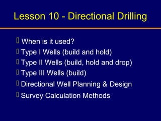

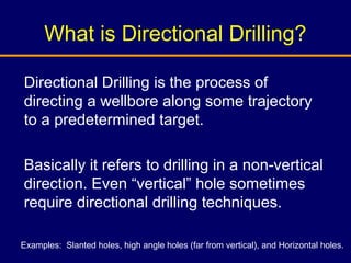
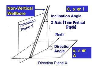


Directional drilling is the process of directing a wellbore along a non-vertical trajectory towards a predetermined target. It involves techniques like whipstocks, jet bits, and downhole motors to gradually build angle in the wellbore. There are three main types of directional well paths: Type I involves continuously building angle to a maximum and then holding; Type II involves building, holding, and dropping the angle; Type III only involves continuously building angle. Survey calculation methods like the average angle method are used to determine the wellbore position between survey points by calculating average inclination and azimuth angles.