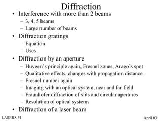
This document discusses several topics related to diffraction:
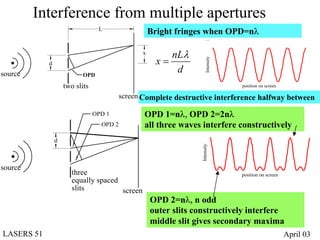
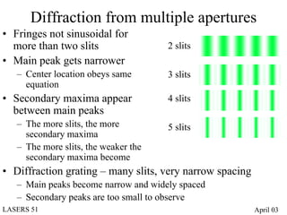
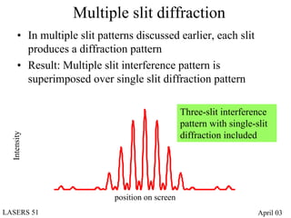
- Diffraction occurs when light encounters multiple beams, such as through diffraction gratings with many slits or apertures.
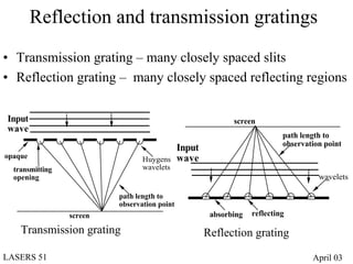
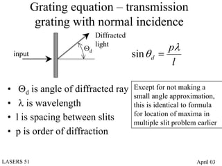
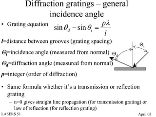
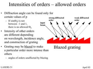
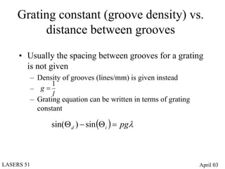
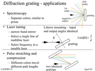
- Diffraction gratings display interference patterns that follow the grating equation and can be used for spectroscopy and laser tuning.
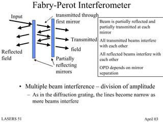
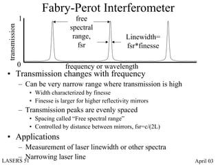
- Fabry-Perot interferometers create multiple beam interference between partially reflecting mirrors, producing a series of evenly spaced transmission peaks used for linewidth measurement and laser narrowing.
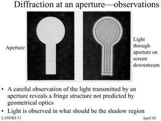
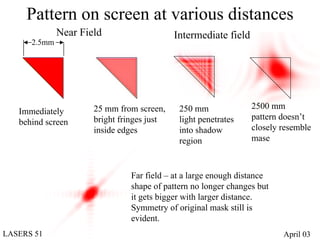
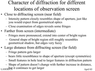
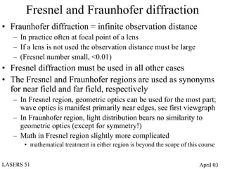
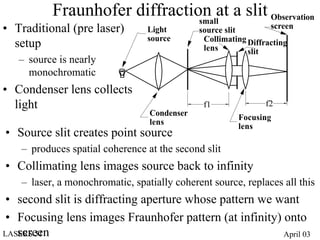
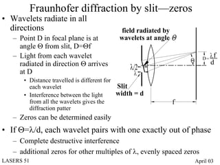
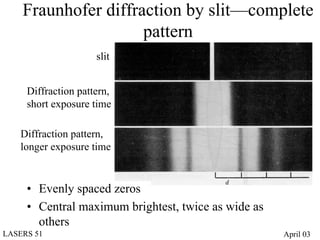
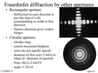
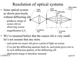
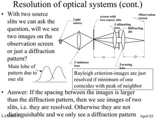
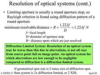
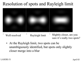
- Diffraction at an aperture, such as a single slit, results in qualitative effects on the diffraction pattern that change with propagation distance.