Downloaded 539 times

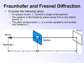
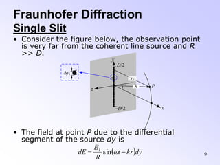

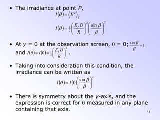


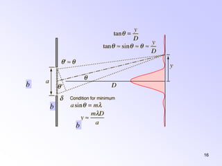
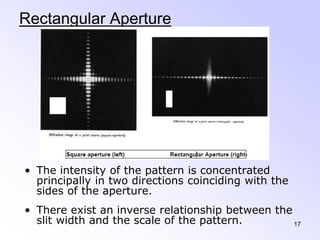
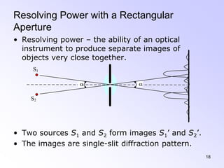


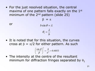
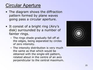

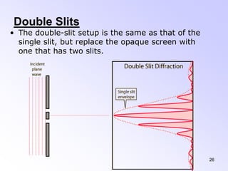
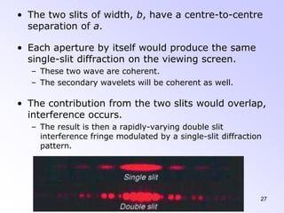


This document discusses the principles and phenomena of diffraction. It begins by defining diffraction as the deviation of light from rectilinear propagation that occurs when a portion of a wavefront is obstructed. The Huygens-Fresnel principle is introduced, which states that every point on a wavefront acts as a secondary source of spherical wavelets. Diffraction patterns can be classified as either Fraunhofer or Fresnel diffraction depending on the separation between the aperture and viewing screen. Examples of diffraction from single slits, circular apertures, and double slits are analyzed. Rayleigh's criterion for resolving power with rectangular apertures is also described.