Downloaded 23 times


![Type of Polarization
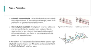
o Partially Polarized Light: Partially polarized light, like natural light, can be represented in the form of a
superposition of two inherent plane of oscillations.
Degree of Polarization: We define the degree of polarization with the help of the following expression.
𝑃 = ( 𝐼max −𝐼𝑚𝑖𝑛 )/ (𝐼𝑚𝑎𝑥 + 𝐼𝑚𝑖𝑛)
% Polarization =[( 𝐼max −𝐼𝑚𝑖𝑛 )/ (𝐼𝑚𝑎𝑥 + 𝐼𝑚𝑖𝑛)] × 100
The intensity of the transmitted light will change within the limits from 𝐼𝑚𝑎𝑥 to 𝐼𝑚𝑖𝑛
• For plane polarized light 𝐼𝑚𝑖𝑛 = 0, and hence P = 1 , and the 1 % polarization is 100% .
• For natural light, 𝐼𝑚𝑎𝑥 = 𝐼𝑚𝑖𝑛 , and hence P =0 and the % polarization is zero .
If 𝐼𝑚𝑎𝑥 = 2 𝐼𝑚𝑖𝑛, P = 0.33 and polarization = 100/3 =33%](https://image.slidesharecdn.com/polarizationoflight-220328115001/85/Polarization-of-Light-pptx-6-320.jpg)
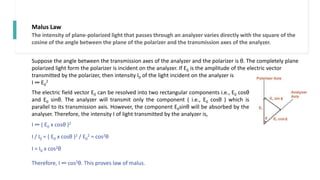
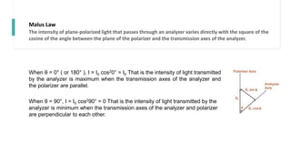
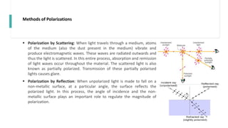
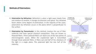
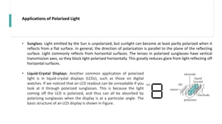
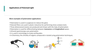

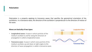
Polarization is a property of transverse waves that describes the orientation of oscillations perpendicular to the direction of motion. Light waves can be plane, circularly, or elliptically polarized depending on the locus of the electric field vector over time. The intensity of light transmitted through a polarizing filter varies directly with the square of the cosine of the angle between the polarizer and analyzer. Polarization occurs through scattering, reflection, refraction, and transmission and has applications in sunglasses, LCD displays, 3D movies, and spectroscopy.


