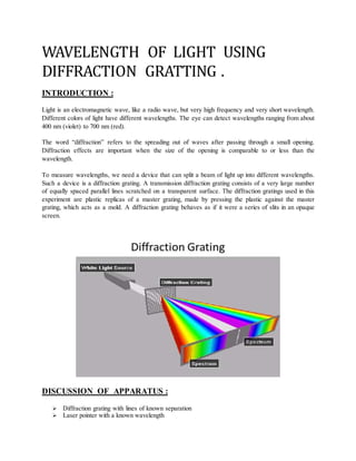
This document describes using a diffraction grating to measure the wavelength of light. A diffraction grating consists of parallel lines that split light into different wavelengths at specific angles. The wavelength can be calculated using the grating's line spacing and the angle of the split beams. The procedure involves shining a laser through a grating and measuring the angle of the first diffraction pattern to calculate the wavelength using the diffraction grating equation. This allows verifying the laser's specified wavelength.
POLARIZATION
Polarization is a property of waves that can oscillate with more than one orientation.
Electromagnetic waves such as light exhibit polarization, as do some other types of wave, such as gravitational waves.
Sound waves in a gas or liquid do not exhibit polarization, since the oscillation is always in the direction the wave travels.
Light waves superimpose each other and the redistribution of energy due to this can be observed in terms of well defined patterns of maxima and minima. Wherein, maxima refers to more energy and minima refers to less energy. Diffraction can also be called as interference in secondary wavelets.
Polarization of Light and its Application (healthkura.com)Bikash Sapkota
Download link ❤❤https://healthkura.com/eye-ppt/29/❤❤
Dear viewers Check Out my other piece of works at ❤❤❤ https://healthkura.com/eye-ppt/ ❤❤❤
polarization of light & its application.
PRESENTATION LAYOUT
Concept of Polarization
Types of Polarization
Methods of achieving Polarization
Applications of Polarization
POLARIZATION
Transforming unpolarized light into polarized light
Restriction of electric field vector E in a particular plane so that vibration occurs in a single plane
Characteristic of transverse wave
Longitudinal waves can’t be polarized; direction of their oscillation is along the direction of propagation.............
For Further Reading
•Optics by Tunnacliffe
•Optics and Refraction by A.K. Khurana
•Principle of Physics, Ayam Publication
•Internet
Interference of light refers to the redistribution of light energy due to superposition of two light waves. This superposition leads to a pattern of alternate dark and bright fringes. These dark and bright fringes are called as minima and maxima respectively.
To detemine the wavelength of semiconductor laserPraveen Vaidya
The laser is part of almost all industrial sectors now. Laser is a coherent highly monochromatic concentrated beam of light.
Right from the computer data reading to metal welding the laser is used. The PowerPoint presentation here explains the laser experiment to determine the wavelength of a semiconductor laser, my the method of Grazing incidence (diffraction over the graduations of metal scale). The aim is to study the diffraction of patterns of laser scattered from the graduations of metal scale and hence determine the wavelength. The experiment is part of the physics curriculum in Technological universities and other science colleges.
Phys 212/216L Experiment
Interference and Diffraction
Spring 2011 1
Figure 1 Geometry of Two-Slit Interference
I. Introduction and Objective
This lab1 focuses on the nature and behavior of light. The wave properties of light are most easily demonstrated
by interference and diffraction of light as it passes through narrow slits. The wave nature of light results in a
pattern with a series of bright and dark regions related to the wavelength of the light and the number and size of
the slits.
You will examine the interference and diffraction patterns created by performing single and double slit
experiments using two different lasers. By analyzing the double slit interference patterns, you will determine the
wavelength of each source. Then using the known wavelengths of each laser, you will analyze single slit
diffraction patterns and determine the slit width. You will also compare the interference pattern produced in the
two slit experiment to the diffraction pattern produced in the single slit experiment.
II. Theory
Huygen’s principle can be used to explain the patterns formed when light passes through either a double or
single slit. For two-slit interference, each slit acts as a new source of light. Since the slits are illuminated by the
same wave front, these sources are in phase. Where the wave fronts from the two sources overlap, an
interference pattern is formed. If you look closely at a two slit interference pattern, you will notice that the
intensity of the fringes varies.
a) Two Slit Interference
In 1801, Thomas Young demonstrated the wave
nature of light by observing the pattern formed
when a narrow beam of light was sent through a
pair of narrow slits. In a similar way, if a laser beam
is passed through two vertical narrow slits onto a
distant screen, a horizontal pattern of equally
spaced dots is observed. The bright and dark
regions are due to the constructive and destructive
interference of the light waves from the two slits.
The geometry of the double slit setup is shown in
the Figure 1 where d is the slit separation, L is the
distance from the slits to the screen, and y is the
distance measured from the center of the pattern.
When the distance which the light beams travel from the two slits to the screen differs by one-half wavelength,
the two beams will cancel, and a dark region (a minimum) will be observed. When the screen is far from the
slits (the length L is much greater than the slit separation, d), the positions of these minima can be given by
d
L
ny
λ
)( 2
1+= ,...2,1,0 ±±=n (Dark fringes of a double slit) (1a)
and the position of the interference maxima are given by
d
L
ny
λ
= ,...2,1,0 ±±=n (Bright fringes of a double slit) (1b)
where n is an integer, and λ is the wavelength of the light. It can be shown from equation (1a) that the minima
in the light are equally spaced with a spacing W given by
d
L
W
λ
= .
Resolution is the distance at which a lens can barely distinguish two separate objects.
Resolution is limited by aberrations and by diffraction. Aberrations can be minimized, but diffraction is unavoidable; it is due to the size of the lens compared to the wavelength of the light.
Advance electronics, semiconductor devices handwritten notes in pdf form
if anybody needs the soft of this book cand contact to me I have also a solution of this book in pdf form my contact no
03201611448
METHOD OF HARDNESS MEASUREMENT:
There are two types of measurement of hardness of a compounds:
• Static indentation
• Rebound testing
STATIC INDENTATION:
• Static indentation involves pressing a ball diamond or other types of indenter under a specified constant load into surface of material and measuring the length width or depth of the indentation.
• The measured indentation size is then converted to a hardness number specified to the scale adopted.
• In general the harder the material the better the resistance and thus the smaller the indentation.
REBOUND TESTING:
• Rebound testing involves dropping an indenter o to the surface of specimen and measuring rebound height of the indenter.
• The potential energy at the initial height is converted to kinetic energy when the indenter is released.
• A fraction of the kinetic energy is consume for plastic deformation on impact living some kinetic energy after impact to convert back to potential energy and achieve a certain rebound height of the indenter.
• The rebound height the measure by the instrument is then converted to a hardness number.
Hard materials are difficult to cut and shape then softer ones. They are also usually more brittle which means that do not bend much but can shatter. Hard material are used in cutting tool machines and other industrial goods. Hardness test are important in material science. The MOHS scale of mineral hardness test the hardness of minerals. The Brinell scale and various compression tests and rebound test are more used for metals and artificial materials
Theoretically investigate the nature of direct band gap of novel materialsUCP
DIRECT BAND GAP:
In the direct band gap band to band recombination and generation occur.
Band to band recombination:
In band-to-band recombination electron from conduction band directly come back to valance band (in valance band holes are present which are the deficiency of electrons which are form when electrons leave valance band and go to conduction band) The electrons and holes annihilate each other the excess energy release during this process in the form of light called photon or in the form of thermal energy.
Band to band recombination is called direct band recombination.
Band to band generation:
In band-to-band generation electron is excited directly from valance band in to the conduction band after absorbing the thermal energy or photon(light) as shown in fig. given bellow.
If the thermal energy is absorbed this process is called thermal generation
If the light is absorbed this process is called photo generation
Momentum consideration in direct band:
In the EK plot K is the parameter proportional to momentum of electron.
GaAs is a notable member of direct band semiconductor
Photons, being massless entities carry the little momentum.
In direct band-band recombination K-value of electron’s and holes are all bounced k=o.as shown in figure given bellow, the little change in momentum is required for the recombination process to proceed.
For conservation of energy and momentum simply the photon is emitted
Energy and momentum have parabolic shape
The French Revolution, which began in 1789, was a period of radical social and political upheaval in France. It marked the decline of absolute monarchies, the rise of secular and democratic republics, and the eventual rise of Napoleon Bonaparte. This revolutionary period is crucial in understanding the transition from feudalism to modernity in Europe.
For more information, visit-www.vavaclasses.com
2024.06.01 Introducing a competency framework for languag learning materials ...Sandy Millin
http://sandymillin.wordpress.com/iateflwebinar2024
Published classroom materials form the basis of syllabuses, drive teacher professional development, and have a potentially huge influence on learners, teachers and education systems. All teachers also create their own materials, whether a few sentences on a blackboard, a highly-structured fully-realised online course, or anything in between. Despite this, the knowledge and skills needed to create effective language learning materials are rarely part of teacher training, and are mostly learnt by trial and error.
Knowledge and skills frameworks, generally called competency frameworks, for ELT teachers, trainers and managers have existed for a few years now. However, until I created one for my MA dissertation, there wasn’t one drawing together what we need to know and do to be able to effectively produce language learning materials.
This webinar will introduce you to my framework, highlighting the key competencies I identified from my research. It will also show how anybody involved in language teaching (any language, not just English!), teacher training, managing schools or developing language learning materials can benefit from using the framework.
Honest Reviews of Tim Han LMA Course Program.pptxtimhan337
Personal development courses are widely available today, with each one promising life-changing outcomes. Tim Han’s Life Mastery Achievers (LMA) Course has drawn a lot of interest. In addition to offering my frank assessment of Success Insider’s LMA Course, this piece examines the course’s effects via a variety of Tim Han LMA course reviews and Success Insider comments.
Model Attribute Check Company Auto PropertyCeline George
In Odoo, the multi-company feature allows you to manage multiple companies within a single Odoo database instance. Each company can have its own configurations while still sharing common resources such as products, customers, and suppliers.
Read| The latest issue of The Challenger is here! We are thrilled to announce that our school paper has qualified for the NATIONAL SCHOOLS PRESS CONFERENCE (NSPC) 2024. Thank you for your unwavering support and trust. Dive into the stories that made us stand out!
Introduction to AI for Nonprofits with Tapp NetworkTechSoup
Dive into the world of AI! Experts Jon Hill and Tareq Monaur will guide you through AI's role in enhancing nonprofit websites and basic marketing strategies, making it easy to understand and apply.
Synthetic Fiber Construction in lab .pptxPavel ( NSTU)
Synthetic fiber production is a fascinating and complex field that blends chemistry, engineering, and environmental science. By understanding these aspects, students can gain a comprehensive view of synthetic fiber production, its impact on society and the environment, and the potential for future innovations. Synthetic fibers play a crucial role in modern society, impacting various aspects of daily life, industry, and the environment. ynthetic fibers are integral to modern life, offering a range of benefits from cost-effectiveness and versatility to innovative applications and performance characteristics. While they pose environmental challenges, ongoing research and development aim to create more sustainable and eco-friendly alternatives. Understanding the importance of synthetic fibers helps in appreciating their role in the economy, industry, and daily life, while also emphasizing the need for sustainable practices and innovation.
Embracing GenAI - A Strategic ImperativePeter Windle
Artificial Intelligence (AI) technologies such as Generative AI, Image Generators and Large Language Models have had a dramatic impact on teaching, learning and assessment over the past 18 months. The most immediate threat AI posed was to Academic Integrity with Higher Education Institutes (HEIs) focusing their efforts on combating the use of GenAI in assessment. Guidelines were developed for staff and students, policies put in place too. Innovative educators have forged paths in the use of Generative AI for teaching, learning and assessments leading to pockets of transformation springing up across HEIs, often with little or no top-down guidance, support or direction.
This Gasta posits a strategic approach to integrating AI into HEIs to prepare staff, students and the curriculum for an evolving world and workplace. We will highlight the advantages of working with these technologies beyond the realm of teaching, learning and assessment by considering prompt engineering skills, industry impact, curriculum changes, and the need for staff upskilling. In contrast, not engaging strategically with Generative AI poses risks, including falling behind peers, missed opportunities and failing to ensure our graduates remain employable. The rapid evolution of AI technologies necessitates a proactive and strategic approach if we are to remain relevant.
Acetabularia Information For Class 9 .docxvaibhavrinwa19
Acetabularia acetabulum is a single-celled green alga that in its vegetative state is morphologically differentiated into a basal rhizoid and an axially elongated stalk, which bears whorls of branching hairs. The single diploid nucleus resides in the rhizoid.
Welcome to TechSoup New Member Orientation and Q&A (May 2024).pdfTechSoup
In this webinar you will learn how your organization can access TechSoup's wide variety of product discount and donation programs. From hardware to software, we'll give you a tour of the tools available to help your nonprofit with productivity, collaboration, financial management, donor tracking, security, and more.
Welcome to TechSoup New Member Orientation and Q&A (May 2024).pdf
Wavelength of light using diffraction gratting .
1. WAVELENGTH OF LIGHT USING
DIFFRACTION GRATTING .
INTRODUCTION :
Light is an electromagnetic wave, like a radio wave, but very high frequency and very short wavelength.
Different colors of light have different wavelengths. The eye can detect wavelengths ranging from about
400 nm (violet) to 700 nm (red).
The word “diffraction” refers to the spreading out of waves after passing through a small opening.
Diffraction effects are important when the size of the opening is comparable to or less than the
wavelength.
To measure wavelengths, we need a device that can split a beam of light up into different wavelengths.
Such a device is a diffraction grating. A transmission diffraction grating consists of a very large number
of equally spaced parallel lines scratched on a transparent surface. The diffraction gratings used in this
experiment are plastic replicas of a master grating, made by pressing the plastic against the master
grating, which acts as a mold. A diffraction grating behaves as if it were a series of slits in an opaque
screen.
DISCUSSION OF APPARATUS :
Diffraction grating with lines of known separation
Laser pointer with a known wavelength
2. Meter stick
Ruler
Binder clips
Index card
Tape
Protractor
THEORY AND BACKGROUND OF EXPERIMENT:
A diffraction grating is made by making many parallel scratches on the surface of a flat piece of some
transparent material. It is possible to put some large number of scratches per cm on the material. The
distribution of wavelengths of light given off by a particular source is called the spectrum of that source.
An incandescent lamp gives off a continuous spectrum containing all wavelengths in the visible part of it,
from red to violet. A laser emits light of a single wavelength. A spectral lamp that contains the excited
vapor of a particular element emits a spectrum that contains a few discrete wavelengths that are
characteristic of that atom. The object of this experiment is to measure some of these wavelengths, and
then to use observations of diffraction from a compact disc to infer spacing of information stored on the
CD.
Consider a diffraction grating consisting of a very large number of slits. When all the waves spreading out
from all the slits are added up, they cancel out everywhere except in certain directions along which all the
crests of all the waves exactly coincide and add up constructively. These particular directions are
determined by the wavelength of the light λ and the distance d, between centers of adjacent slits in the
grating, known as the grating spacing. An example of the constructive interference that arises for just two
slits.
3. PROCEDURE :
Tape an index card to the wall so the blank side is facing you.
Lay the meter stick on a table or the floor so the 0 meets the index card.
Mount the later pointer at the end of the meter stick, pointing towards the index card.
Mount the diffraction grating a few centimeters from the index card so the lines are vertical.
Turn off the lights in the room and turn on the laser pointer.
Use your protractor to measure the angle between the meter stick and the first order visible
band.
Use the formula Where λ is the wavelength, in meters d is the distance in meters between
lines on the diffraction grating θ is the angle and n is the order. Unless the room is extremely
dark, you will only be able to see the first order, so n=1.
Compare your calculated wavelength to the wavelength provided by the manufacturer of the
laser.
Repeat for different lengths along the meter stick.
OBSERVATIONS :
The patterns that arise for more than two slits sharpen the directions of the brightest regions. For a
diffraction grating, the directions of maximum intensity can be specified by a series of angles. The angles
are measured relative to the line OP, which is parallel to the light falling on the diffraction grating
initially.
4. On either side of OP are two directions of maximum intensity (lines OA1 and OB1 ) known as the "first
order" maxima, at angle θ1 given by
Two other directions are lines OA2 and OB2 (the "second order" maximum) at angle θ2 given by
Higher order maxima may be observed at angles given by the general formula
The diffraction gratings used in this lab have 600 lines per mm. So the spacing d between lines is simply
RESULT ANALYSIS :
Diffraction gratings diffract, or split, light periodically, meaning the light splits into several beams with a
given angular separation. In this experiment, the first period, n=1, will be the brightest spot on the index
card (besides the straight path of the laser, of course) after the grating splits the rays from the laser
pointer. Using the formula above, We can verify the wavelength of light using what the manufacturer of
the laser pointer says it is. If the room is dark enough, we may even be able to measure the 2nd and 3rd
periods and plug n = 2 and n = 3 into the equation, respectively. It should yield the same result.