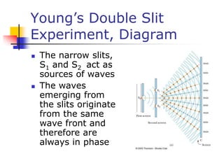
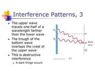
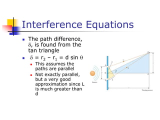
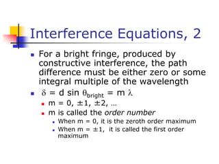
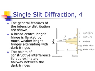
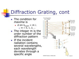
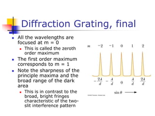
Chapter 24
Wave Optics
Wave Optics
 The wave nature of light is needed
to explain various phenomena
 Interference
 Diffraction
 Polarization
 The particle nature of light was the
basis for ray (geometric) optics
Interference
 Light waves interfere with each
other much like mechanical waves
do
 All interference associated with
light waves arises when the
electromagnetic fields that
constitute the individual waves
combine
Conditions for Interference
 For sustained interference between
two sources of light to be
observed, there are two conditions
which must be met
 The sources must be coherent
 They must maintain a constant phase
with respect to each other
 The waves must have identical
wavelengths
Producing Coherent
Sources
 Light from a monochromatic source is
allowed to pass through a narrow slit
 The light from the single slit is allowed
to fall on a screen containing two
narrow slits
 The first slit is needed to insure the
light comes from a tiny region of the
source which is coherent
 Old method
Producing Coherent
Sources, cont
 Currently, it is much more
common to use a laser as a
coherent source
 The laser produces an intense,
coherent, monochromatic beam
over a width of several millimeters
 The laser light can be used to
illuminate multiple slits directly
Young’s Double Slit
Experiment
 Thomas Young first demonstrated
interference in light waves from two
sources in 1801
 Light is incident on a screen with a
narrow slit, So
 The light waves emerging from this slit
arrive at a second screen that contains
two narrow, parallel slits, S1 and S2
Young’s Double Slit
Experiment, Diagram
 The narrow slits,
S1 and S2 act as
sources of waves
 The waves
emerging from
the slits originate
from the same
wave front and
therefore are
always in phase
Resulting Interference
Pattern
 The light from the two slits form a
visible pattern on a screen
 The pattern consists of a series of
bright and dark parallel bands called
fringes
 Constructive interference occurs where
a bright fringe appears
 Destructive interference results in a
dark fringe
Fringe Pattern
 The fringe pattern
formed from a
Young’s Double Slit
Experiment would
look like this
 The bright areas
represent
constructive
interference
 The dark areas
represent destructive
interference
Interference Patterns
 Constructive
interference
occurs at the
center point
 The two waves
travel the same
distance
 Therefore, they
arrive in phase
Interference Patterns, 2
 The upper wave has
to travel farther than
the lower wave
 The upper wave
travels one
wavelength farther
 Therefore, the waves
arrive in phase
 A bright fringe
occurs
Interference Patterns, 3
 The upper wave
travels one-half of a
wavelength farther
than the lower wave
 The trough of the
bottom wave
overlaps the crest of
the upper wave
 This is destructive
interference
 A dark fringe occurs
Interference Equations
 The path difference,
, is found from the
tan triangle
  = r2 – r1 = d sin 
 This assumes the
paths are parallel
 Not exactly parallel,
but a very good
approximation since L
is much greater than
d
Interference Equations, 2
 For a bright fringe, produced by
constructive interference, the path
difference must be either zero or some
integral multiple of the wavelength
  = d sin bright = m 
 m = 0, ±1, ±2, …
 m is called the order number
 When m = 0, it is the zeroth order maximum
 When m = ±1, it is called the first order
maximum
Interference Equations, 3
 The positions of the fringes can be
measured vertically from the zeroth
order maximum
 y = L tan   L sin 
 Assumptions
 L>>d
 d>>
 Approximation
  is small and therefore the approximation
tan   sin  can be used
Interference Equations, 4
 When destructive interference
occurs, a dark fringe is observed
 This needs a path difference of an
odd half wavelength
  = d sin dark = (m + 1/2) 
 m = 0, ±1, ±2, …
Interference Equations,
final
 For bright fringes
 For dark fringes
Uses for Young’s Double
Slit Experiment
 Young’s Double Slit Experiment
provides a method for measuring
wavelength of the light
 This experiment gave the wave
model of light a great deal of
credibility
 It is inconceivable that particles of
light could cancel each other
Phase Changes Due To
Reflection
 An electromagnetic
wave undergoes a
phase change of
180° upon
reflection from a
medium of higher
index of refraction
than the one in
which it was
traveling
 Analogous to a
reflected pulse on a
string
Phase Changes Due To
Reflection, cont
 There is no phase
change when the
wave is reflected
from a boundary
leading to a medium
of lower index of
refraction
 Analogous to a pulse
in a string reflecting
from a free support
Diffraction
 Huygen’s principle
requires that the
waves spread out after
they pass through slits
 This spreading out of
light from its initial line
of travel is called
diffraction
 In general, diffraction
occurs when waves
pass through small
openings, around
obstacles or by sharp
edges
Diffraction, 2
 A single slit placed between a distant
light source and a screen produces a
diffraction pattern
 It will have a broad, intense central band
 The central band will be flanked by a series
of narrower, less intense secondary bands
 Called secondary maxima
 The central band will also be flanked by a
series of dark bands
 Called minima
Diffraction, 3
 The results of the
single slit cannot be
explained by
geometric optics
 Geometric optics
would say that light
rays traveling in
straight lines should
cast a sharp image of
the slit on the screen
Fraunhofer Diffraction
 Fraunhofer Diffraction
occurs when the rays
leave the diffracting
object in parallel
directions
 Screen very far from the
slit
 Converging lens (shown)
 A bright fringe is seen
along the axis ( = 0)
with alternating bright
and dark fringes on each
side
Single Slit Diffraction
 According to Huygen’s
principle, each portion
of the slit acts as a
source of waves
 The light from one
portion of the slit can
interfere with light from
another portion
 The resultant intensity
on the screen depends
on the direction 
Single Slit Diffraction, 2
 All the waves that originate at the slit
are in phase
 Wave 1 travels farther than wave 3 by
an amount equal to the path difference
(a/2) sin 
 If this path difference is exactly half of
a wavelength, the two waves cancel
each other and destructive interference
results
Single Slit Diffraction, 3
 In general, destructive interference
occurs for a single slit of width a when
sin dark = m / a
 m = 1, 2, 3, …
 Doesn’t give any information about the
variations in intensity along the screen
Single Slit Diffraction, 4
 The general features of
the intensity distribution
are shown
 A broad central bright
fringe is flanked by
much weaker bright
fringes alternating with
dark fringes
 The points of
constructive interference
lie approximately
halfway between the
dark fringes
Diffraction Grating
 The diffracting grating consists of
many equally spaced parallel slits
 A typical grating contains several
thousand lines per centimeter
 The intensity of the pattern on the
screen is the result of the
combined effects of interference
and diffraction
Diffraction Grating, cont
 The condition for
maxima is
 d sin bright = m 
 m = 0, 1, 2, …
 The integer m is the
order number of the
diffraction pattern
 If the incident
radiation contains
several wavelengths,
each wavelength
deviates through a
specific angle
Diffraction Grating, final
 All the wavelengths are
focused at m = 0
 This is called the zeroth
order maximum
 The first order maximum
corresponds to m = 1
 Note the sharpness of the
principle maxima and the
broad range of the dark
area
 This is in contrast to the
broad, bright fringes
characteristic of the two-
slit interference pattern
Diffraction Grating in CD
Tracking
 A diffraction grating
can be used in a three-
beam method to keep
the beam on a CD on
track
 The central maximum
of the diffraction
pattern is used to read
the information on the
CD
 The two first-order
maxima are used for
steering
Polarization of Light
Waves
 Each atom produces a
wave with its own
orientation of
 All directions of the
electric field vector are
equally possible and
lie in a plane
perpendicular to the
direction of
propagation
 This is an unpolarized
wave
Polarization of Light, cont
 A wave is said to be linearly
polarized if the resultant
electric field vibrates in the
same direction at all times at a
particular point
 Polarization can be obtained
from an unpolarized beam by
 selective absorption
 reflection
 scattering
Polarization by Selective
Absorption
 The most common technique for polarizing
light
 Uses a material that transmits waves whose
electric field vectors in the plane are parallel
to a certain direction and absorbs waves
whose electric field vectors are perpendicular
to that direction
Selective Absorption, cont
 E. H. Land discovered a material
that polarizes light through
selective absorption
 He called the material Polaroid
 The molecules readily absorb light
whose electric field vector is parallel
to their lengths and transmit light
whose electric field vector is
perpendicular to their lengths
Selective Absorption, final
 The intensity of the polarized beam
transmitted through the second
polarizing sheet (the analyzer) varies as
 I = Io cos2 
 Io is the intensity of the polarized wave incident
on the analyzer
 This is known as Malus’ Law and applies to any
two polarizing materials whose transmission axes
are at an angle of  to each other
Polarization by Reflection
 When an unpolarized light beam is
reflected from a surface, the reflected
light is
 Completely polarized
 Partially polarized
 Unpolarized
 It depends on the angle of incidence
 If the angle is 0° or 90°, the reflected beam is
unpolarized
 For angles between this, there is some degree
of polarization
 For one particular angle, the beam is completely
polarized
Polarization by Reflection,
cont
 The angle of incidence for which the
reflected beam is completely polarized
is called the polarizing angle, p
 Brewster’s Law relates the polarizing
angle to the index of refraction for the
material
 p may also be called Brewster’s Angle
Polarization by Scattering
 When light is incident on a system
of particles, the electrons in the
medium can absorb and reradiate
part of the light
 This process is called scattering
 An example of scattering is the
sunlight reaching an observer on
the earth becoming polarized
Polarization by Scattering,
cont
 The horizontal part of the
electric field vector in the
incident wave causes the
charges to vibrate
horizontally
 The vertical part of the
vector simultaneously
causes them to vibrate
vertically
 Horizontally and vertically
polarized waves are
emitted

Engineering Physics Ch:20 WaveOptics.ppt

  • 1.
  • 2.
    Wave Optics  Thewave nature of light is needed to explain various phenomena  Interference  Diffraction  Polarization  The particle nature of light was the basis for ray (geometric) optics
  • 3.
    Interference  Light wavesinterfere with each other much like mechanical waves do  All interference associated with light waves arises when the electromagnetic fields that constitute the individual waves combine
  • 4.
    Conditions for Interference For sustained interference between two sources of light to be observed, there are two conditions which must be met  The sources must be coherent  They must maintain a constant phase with respect to each other  The waves must have identical wavelengths
  • 5.
    Producing Coherent Sources  Lightfrom a monochromatic source is allowed to pass through a narrow slit  The light from the single slit is allowed to fall on a screen containing two narrow slits  The first slit is needed to insure the light comes from a tiny region of the source which is coherent  Old method
  • 6.
    Producing Coherent Sources, cont Currently, it is much more common to use a laser as a coherent source  The laser produces an intense, coherent, monochromatic beam over a width of several millimeters  The laser light can be used to illuminate multiple slits directly
  • 7.
    Young’s Double Slit Experiment Thomas Young first demonstrated interference in light waves from two sources in 1801  Light is incident on a screen with a narrow slit, So  The light waves emerging from this slit arrive at a second screen that contains two narrow, parallel slits, S1 and S2
  • 8.
    Young’s Double Slit Experiment,Diagram  The narrow slits, S1 and S2 act as sources of waves  The waves emerging from the slits originate from the same wave front and therefore are always in phase
  • 9.
    Resulting Interference Pattern  Thelight from the two slits form a visible pattern on a screen  The pattern consists of a series of bright and dark parallel bands called fringes  Constructive interference occurs where a bright fringe appears  Destructive interference results in a dark fringe
  • 10.
    Fringe Pattern  Thefringe pattern formed from a Young’s Double Slit Experiment would look like this  The bright areas represent constructive interference  The dark areas represent destructive interference
  • 11.
    Interference Patterns  Constructive interference occursat the center point  The two waves travel the same distance  Therefore, they arrive in phase
  • 12.
    Interference Patterns, 2 The upper wave has to travel farther than the lower wave  The upper wave travels one wavelength farther  Therefore, the waves arrive in phase  A bright fringe occurs
  • 13.
    Interference Patterns, 3 The upper wave travels one-half of a wavelength farther than the lower wave  The trough of the bottom wave overlaps the crest of the upper wave  This is destructive interference  A dark fringe occurs
  • 14.
    Interference Equations  Thepath difference, , is found from the tan triangle   = r2 – r1 = d sin   This assumes the paths are parallel  Not exactly parallel, but a very good approximation since L is much greater than d
  • 15.
    Interference Equations, 2 For a bright fringe, produced by constructive interference, the path difference must be either zero or some integral multiple of the wavelength   = d sin bright = m   m = 0, ±1, ±2, …  m is called the order number  When m = 0, it is the zeroth order maximum  When m = ±1, it is called the first order maximum
  • 16.
    Interference Equations, 3 The positions of the fringes can be measured vertically from the zeroth order maximum  y = L tan   L sin   Assumptions  L>>d  d>>  Approximation   is small and therefore the approximation tan   sin  can be used
  • 17.
    Interference Equations, 4 When destructive interference occurs, a dark fringe is observed  This needs a path difference of an odd half wavelength   = d sin dark = (m + 1/2)   m = 0, ±1, ±2, …
  • 18.
    Interference Equations, final  Forbright fringes  For dark fringes
  • 19.
    Uses for Young’sDouble Slit Experiment  Young’s Double Slit Experiment provides a method for measuring wavelength of the light  This experiment gave the wave model of light a great deal of credibility  It is inconceivable that particles of light could cancel each other
  • 20.
    Phase Changes DueTo Reflection  An electromagnetic wave undergoes a phase change of 180° upon reflection from a medium of higher index of refraction than the one in which it was traveling  Analogous to a reflected pulse on a string
  • 21.
    Phase Changes DueTo Reflection, cont  There is no phase change when the wave is reflected from a boundary leading to a medium of lower index of refraction  Analogous to a pulse in a string reflecting from a free support
  • 22.
    Diffraction  Huygen’s principle requiresthat the waves spread out after they pass through slits  This spreading out of light from its initial line of travel is called diffraction  In general, diffraction occurs when waves pass through small openings, around obstacles or by sharp edges
  • 23.
    Diffraction, 2  Asingle slit placed between a distant light source and a screen produces a diffraction pattern  It will have a broad, intense central band  The central band will be flanked by a series of narrower, less intense secondary bands  Called secondary maxima  The central band will also be flanked by a series of dark bands  Called minima
  • 24.
    Diffraction, 3  Theresults of the single slit cannot be explained by geometric optics  Geometric optics would say that light rays traveling in straight lines should cast a sharp image of the slit on the screen
  • 25.
    Fraunhofer Diffraction  FraunhoferDiffraction occurs when the rays leave the diffracting object in parallel directions  Screen very far from the slit  Converging lens (shown)  A bright fringe is seen along the axis ( = 0) with alternating bright and dark fringes on each side
  • 26.
    Single Slit Diffraction According to Huygen’s principle, each portion of the slit acts as a source of waves  The light from one portion of the slit can interfere with light from another portion  The resultant intensity on the screen depends on the direction 
  • 27.
    Single Slit Diffraction,2  All the waves that originate at the slit are in phase  Wave 1 travels farther than wave 3 by an amount equal to the path difference (a/2) sin   If this path difference is exactly half of a wavelength, the two waves cancel each other and destructive interference results
  • 28.
    Single Slit Diffraction,3  In general, destructive interference occurs for a single slit of width a when sin dark = m / a  m = 1, 2, 3, …  Doesn’t give any information about the variations in intensity along the screen
  • 29.
    Single Slit Diffraction,4  The general features of the intensity distribution are shown  A broad central bright fringe is flanked by much weaker bright fringes alternating with dark fringes  The points of constructive interference lie approximately halfway between the dark fringes
  • 30.
    Diffraction Grating  Thediffracting grating consists of many equally spaced parallel slits  A typical grating contains several thousand lines per centimeter  The intensity of the pattern on the screen is the result of the combined effects of interference and diffraction
  • 31.
    Diffraction Grating, cont The condition for maxima is  d sin bright = m   m = 0, 1, 2, …  The integer m is the order number of the diffraction pattern  If the incident radiation contains several wavelengths, each wavelength deviates through a specific angle
  • 32.
    Diffraction Grating, final All the wavelengths are focused at m = 0  This is called the zeroth order maximum  The first order maximum corresponds to m = 1  Note the sharpness of the principle maxima and the broad range of the dark area  This is in contrast to the broad, bright fringes characteristic of the two- slit interference pattern
  • 33.
    Diffraction Grating inCD Tracking  A diffraction grating can be used in a three- beam method to keep the beam on a CD on track  The central maximum of the diffraction pattern is used to read the information on the CD  The two first-order maxima are used for steering
  • 34.
    Polarization of Light Waves Each atom produces a wave with its own orientation of  All directions of the electric field vector are equally possible and lie in a plane perpendicular to the direction of propagation  This is an unpolarized wave
  • 35.
    Polarization of Light,cont  A wave is said to be linearly polarized if the resultant electric field vibrates in the same direction at all times at a particular point  Polarization can be obtained from an unpolarized beam by  selective absorption  reflection  scattering
  • 36.
    Polarization by Selective Absorption The most common technique for polarizing light  Uses a material that transmits waves whose electric field vectors in the plane are parallel to a certain direction and absorbs waves whose electric field vectors are perpendicular to that direction
  • 37.
    Selective Absorption, cont E. H. Land discovered a material that polarizes light through selective absorption  He called the material Polaroid  The molecules readily absorb light whose electric field vector is parallel to their lengths and transmit light whose electric field vector is perpendicular to their lengths
  • 38.
    Selective Absorption, final The intensity of the polarized beam transmitted through the second polarizing sheet (the analyzer) varies as  I = Io cos2   Io is the intensity of the polarized wave incident on the analyzer  This is known as Malus’ Law and applies to any two polarizing materials whose transmission axes are at an angle of  to each other
  • 39.
    Polarization by Reflection When an unpolarized light beam is reflected from a surface, the reflected light is  Completely polarized  Partially polarized  Unpolarized  It depends on the angle of incidence  If the angle is 0° or 90°, the reflected beam is unpolarized  For angles between this, there is some degree of polarization  For one particular angle, the beam is completely polarized
  • 40.
    Polarization by Reflection, cont The angle of incidence for which the reflected beam is completely polarized is called the polarizing angle, p  Brewster’s Law relates the polarizing angle to the index of refraction for the material  p may also be called Brewster’s Angle
  • 41.
    Polarization by Scattering When light is incident on a system of particles, the electrons in the medium can absorb and reradiate part of the light  This process is called scattering  An example of scattering is the sunlight reaching an observer on the earth becoming polarized
  • 42.
    Polarization by Scattering, cont The horizontal part of the electric field vector in the incident wave causes the charges to vibrate horizontally  The vertical part of the vector simultaneously causes them to vibrate vertically  Horizontally and vertically polarized waves are emitted