This document summarizes key concepts in wave optics, including:
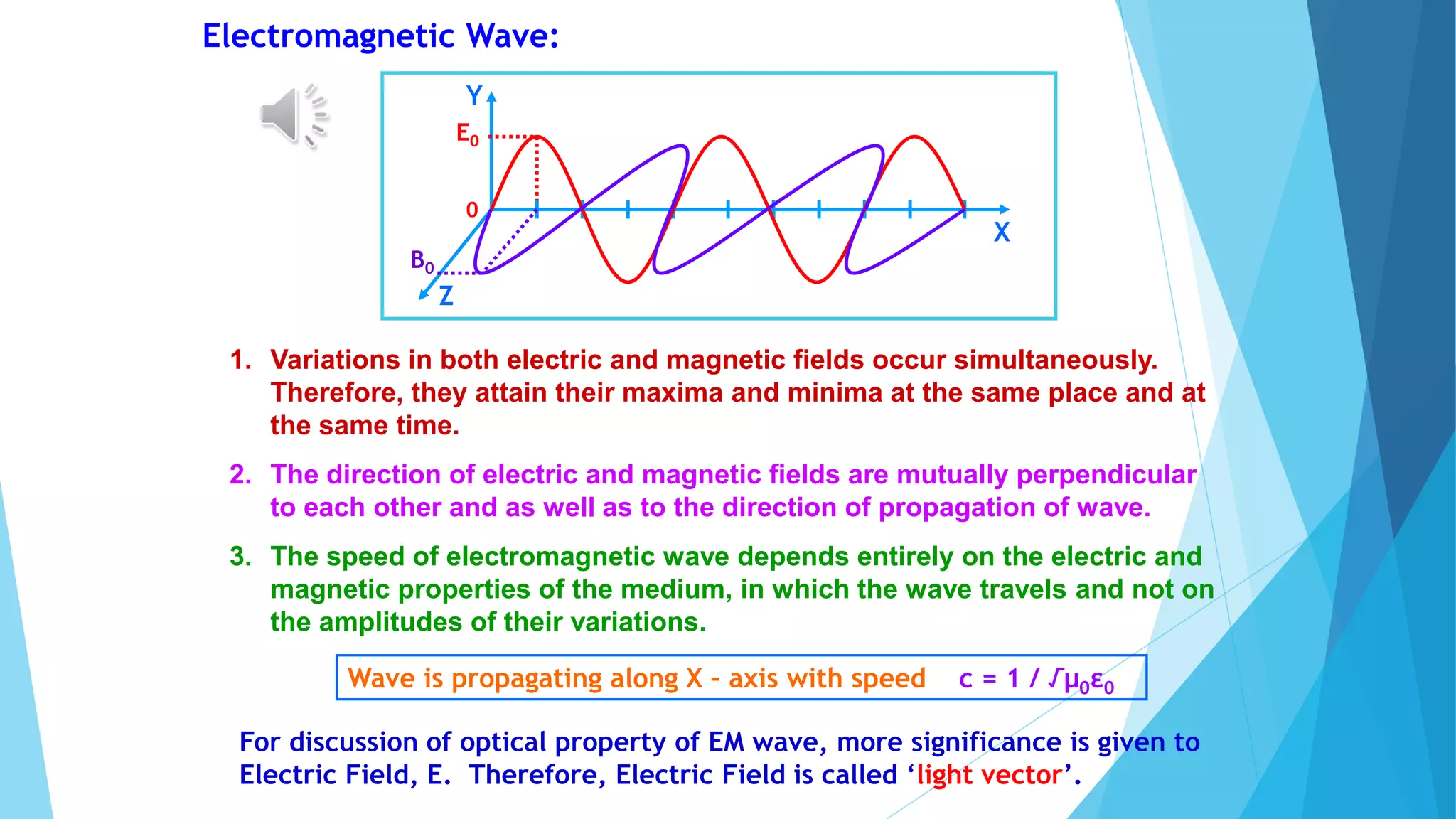
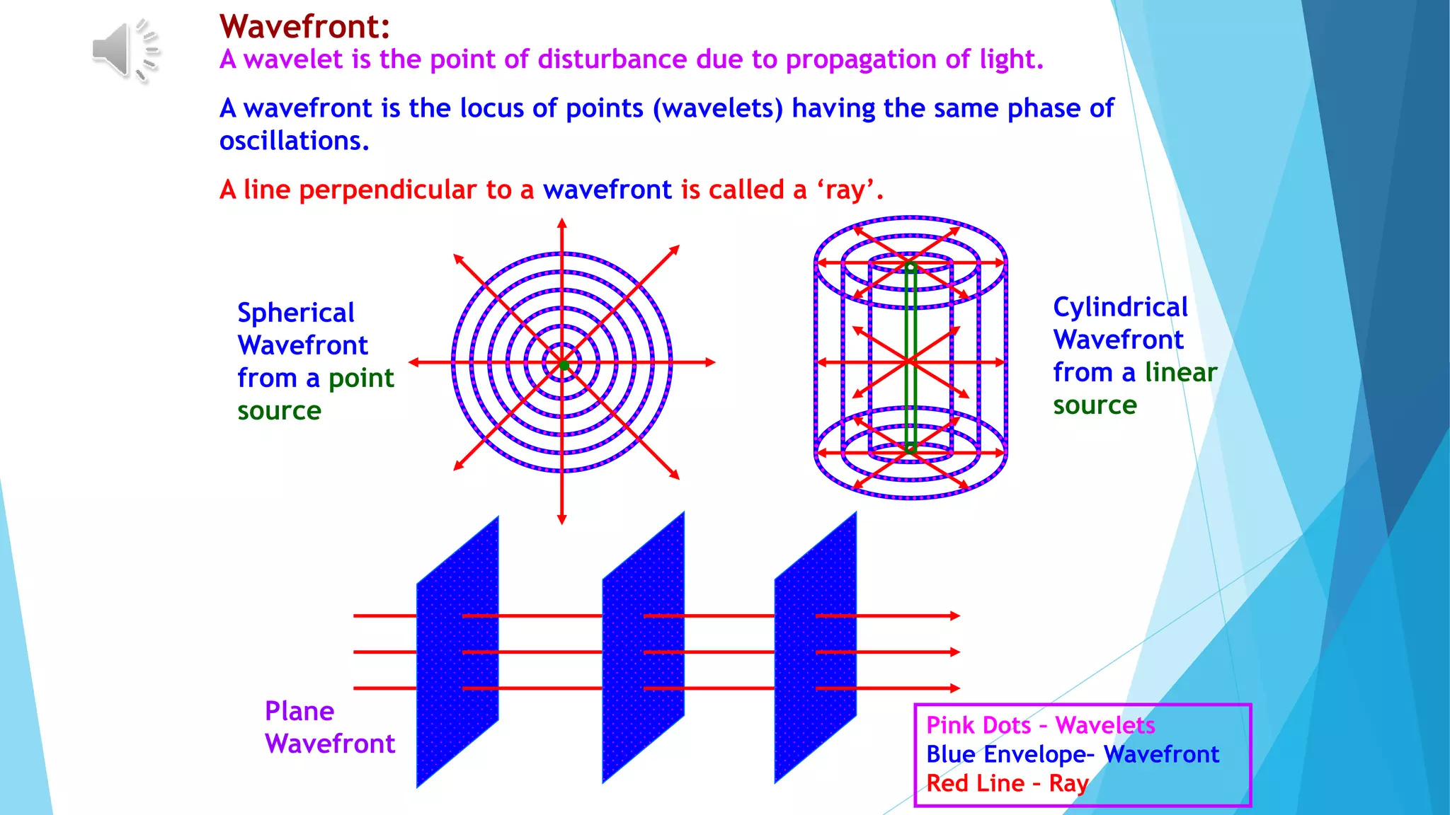
1. Electromagnetic waves propagate as oscillating electric and magnetic fields. Huygens' principle states that each point on a wavefront acts as a secondary source of waves.
2. Reflection and refraction of light can be explained by Huygens' principle and the requirement that light takes the same time to travel between corresponding points on wavefronts.
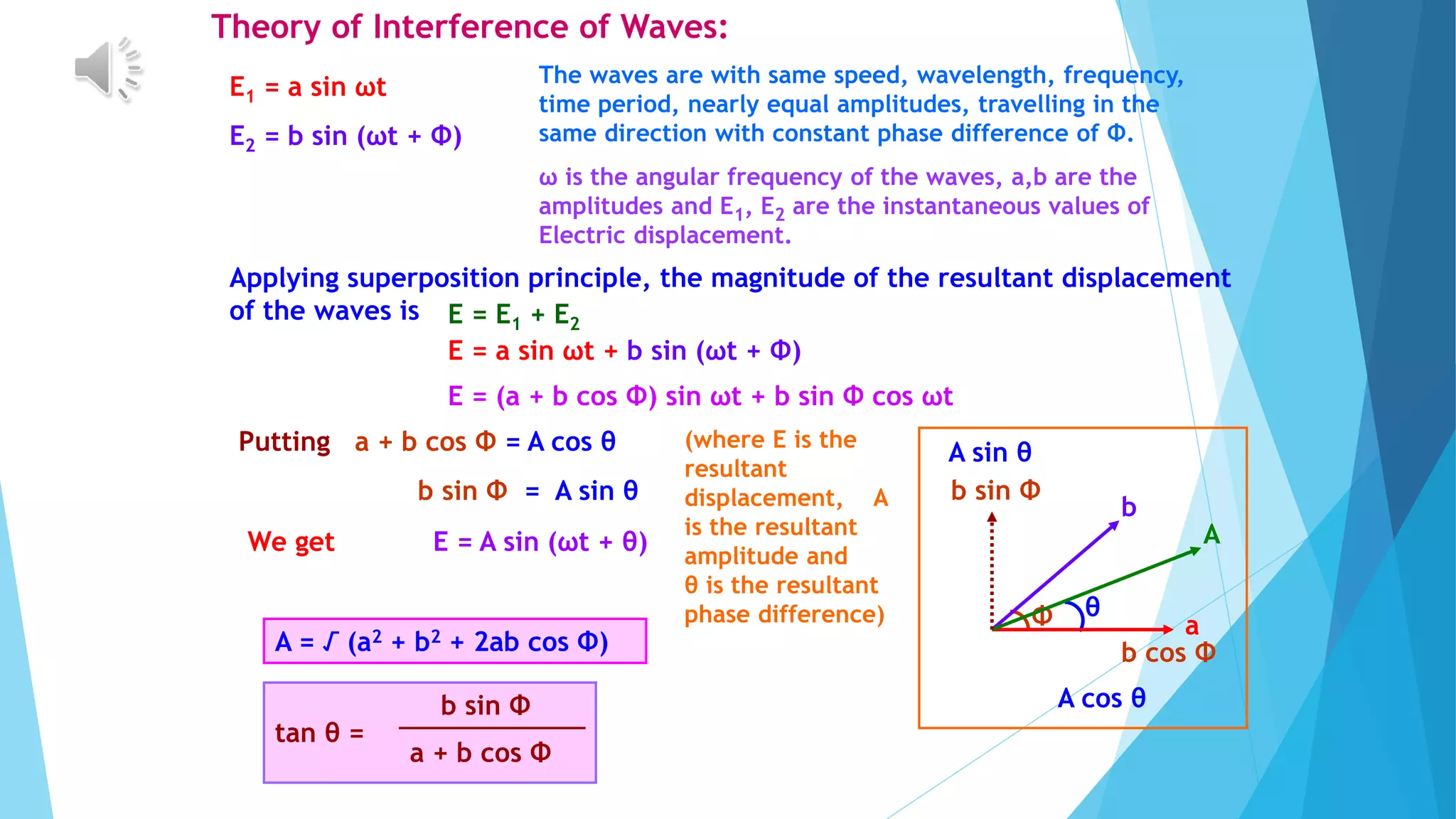
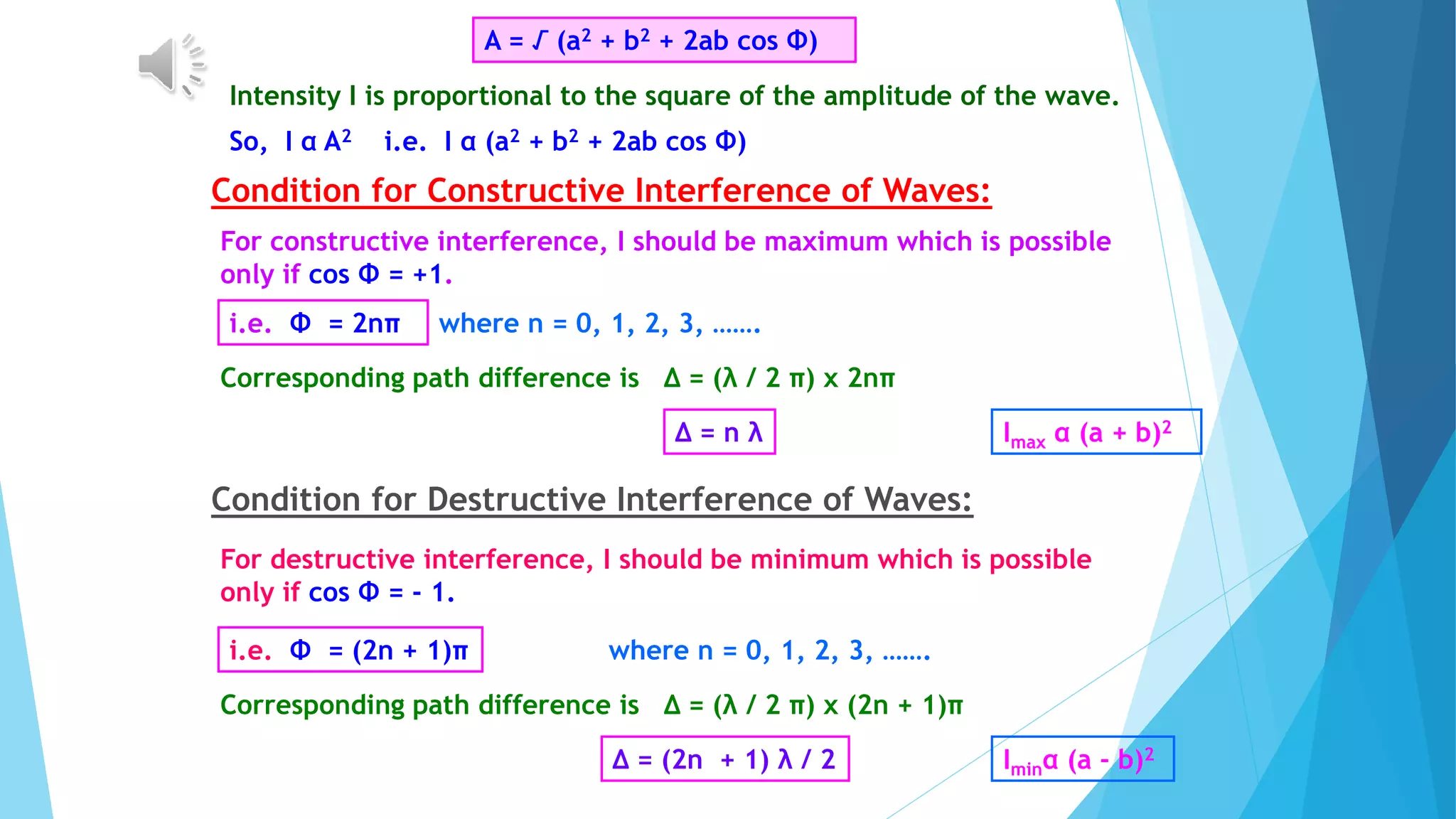
3. Interference patterns from coherent light sources like double slits arise from the constructive and destructive interference of light waves. Diffraction causes light to bend and spread beyond geometric shadows.


![Young’s Double Slit Experiment:
•
S
S • O
P
D
S1
S2
d
y
d/2
d/2
Single Slit Double Slit
Screen
The waves from S1 and S2 reach the point P with some
phase difference and hence path difference
∆ = S2P – S1P
S2P2 – S1P2 = [D2 + {y + (d/2)}2] - [D2 + {y - (d/2)}2]
(S2P – S1P) (S2P + S1P) = 2 yd ∆ (2D) = 2 yd ∆ = yd / D](https://image.slidesharecdn.com/ch-10waveoptics-230816170553-1c887d0f/75/ch-10-wave-optics-pptx-13-2048.jpg)


