Downloaded 297 times
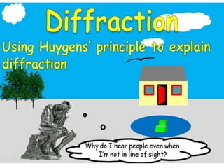
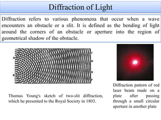

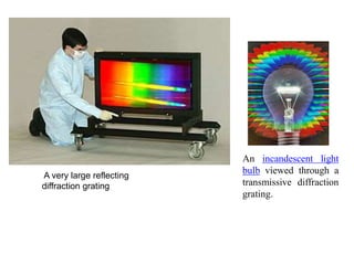

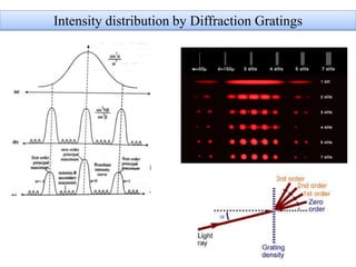
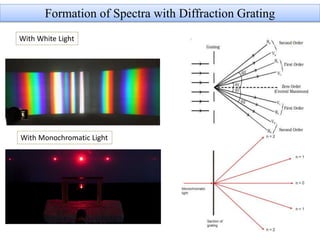
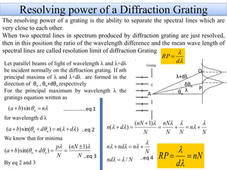


1. Diffraction refers to the bending of light around obstacles or through openings, and results in interference patterns. 2. There are two main types of diffraction: Fresnel diffraction occurs when light passes near an obstacle, while Fraunhofer diffraction occurs when light passes through or around objects and the observation is made far from the obstacle. 3. Diffraction gratings consist of many parallel slits and cause light to diffract into several beams. The angles and intensities of these beams can be determined through analysis of interference from the multiple slits.