Downloaded 103 times
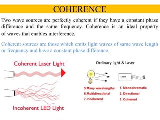
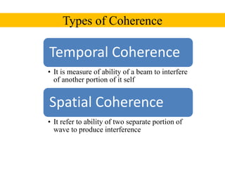
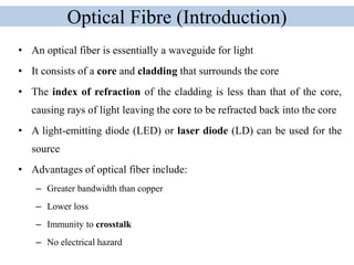

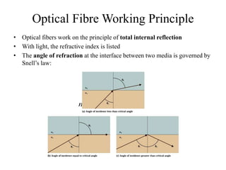
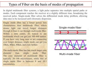

This document discusses coherence and optical fibers. It defines temporal and spatial coherence, which refer to the ability of waves to interfere with themselves or other waves at different times or positions, respectively. Coherence is necessary for interference. Optical fibers transmit light via total internal reflection within a core surrounded by cladding. Fibers can be single-mode or multi-mode depending on the number of propagation modes supported. Numerical aperture specifies the range of angles at which light can enter and propagate within the fiber.


![fiber_optics_1[1].pptx](https://cdn.slidesharecdn.com/ss_thumbnails/fiberoptics11-230305144733-f1e62adc-thumbnail.jpg?width=640&height=640&fit=bounds)