Downloaded 971 times
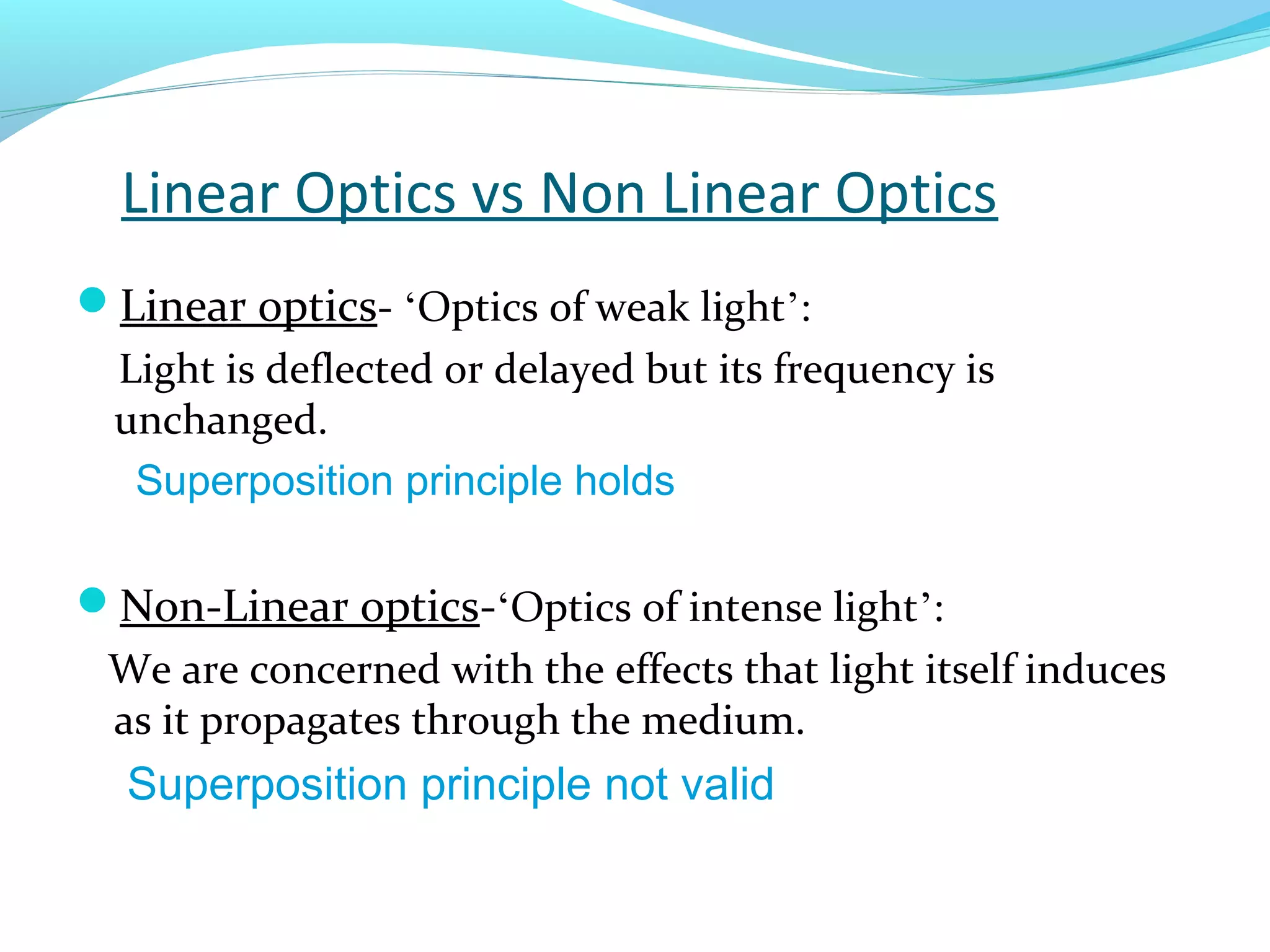
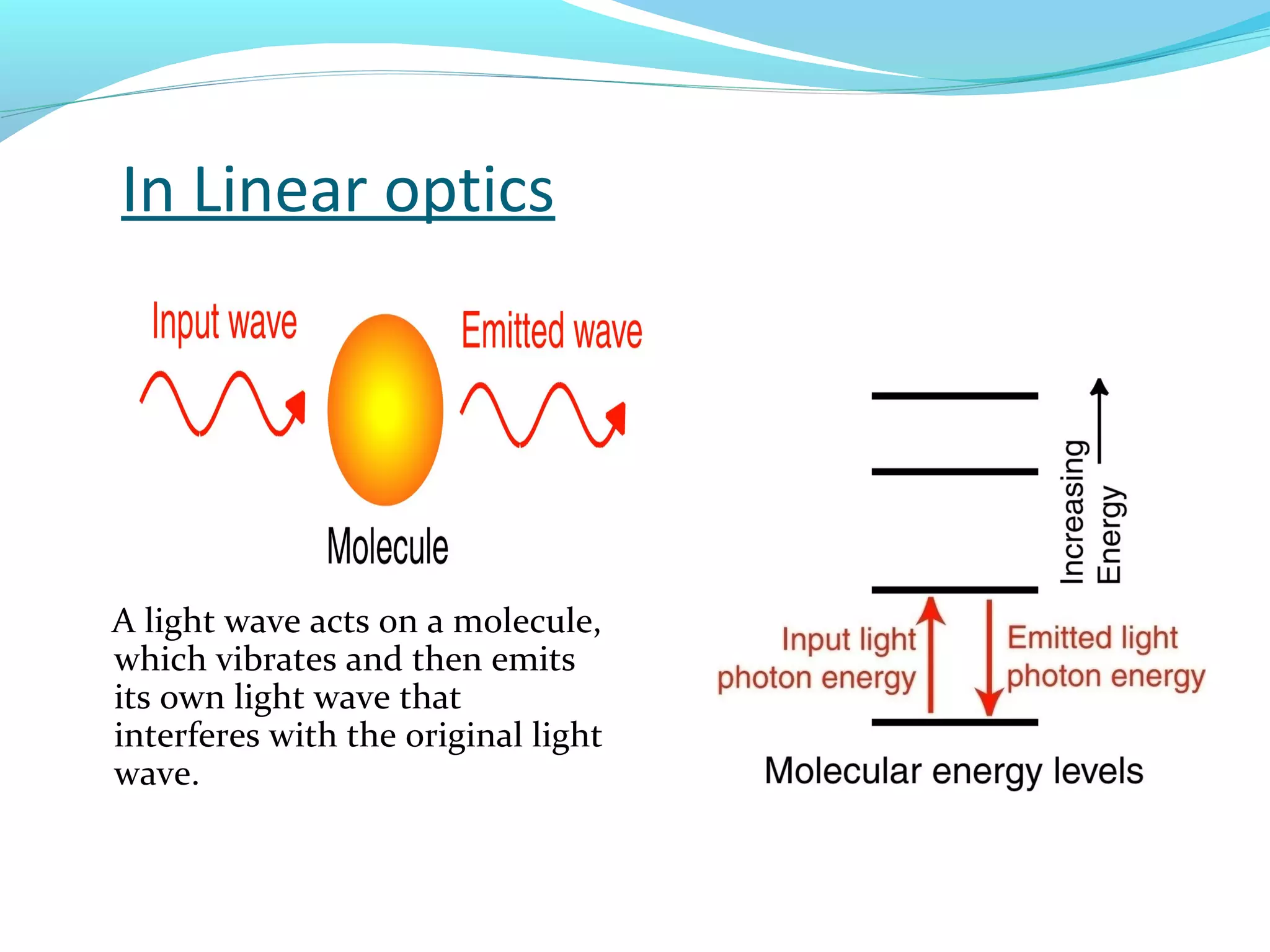

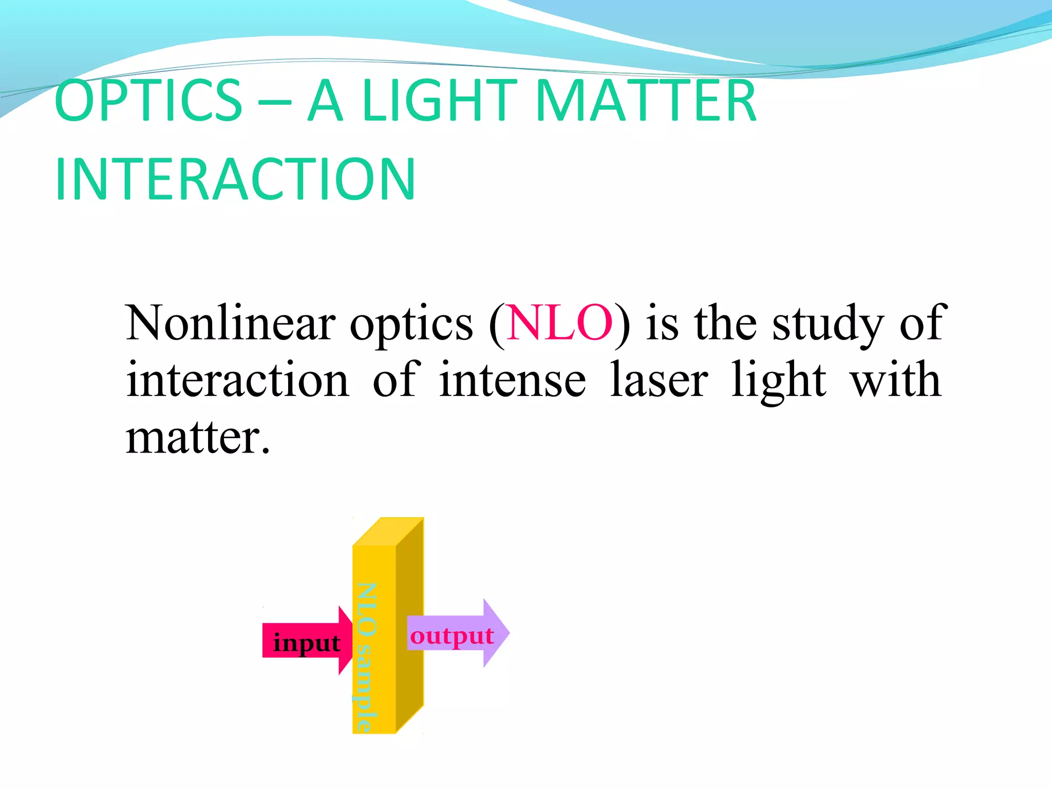
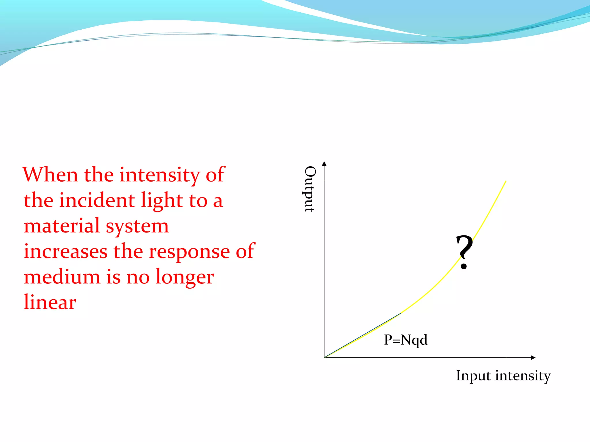

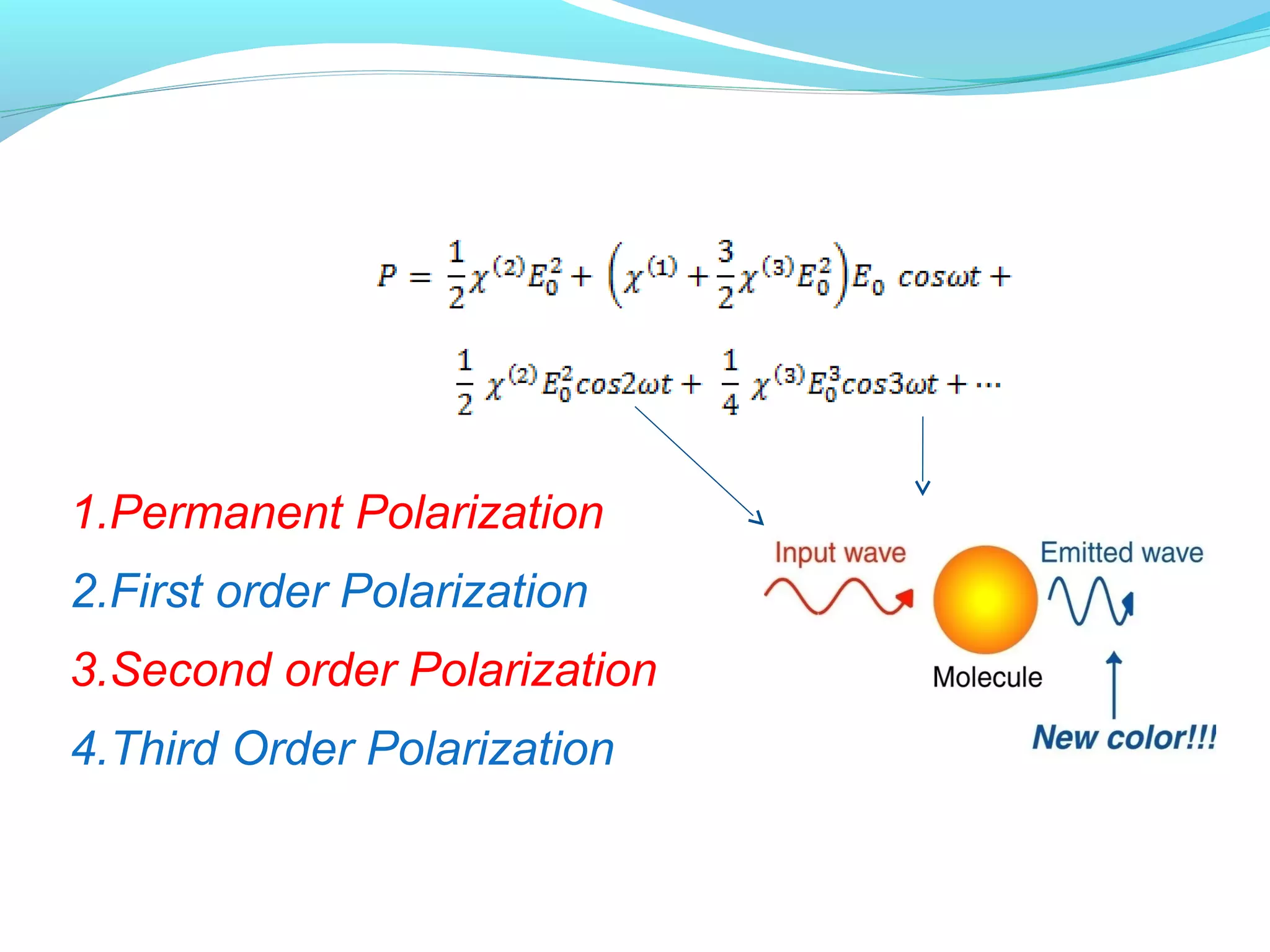
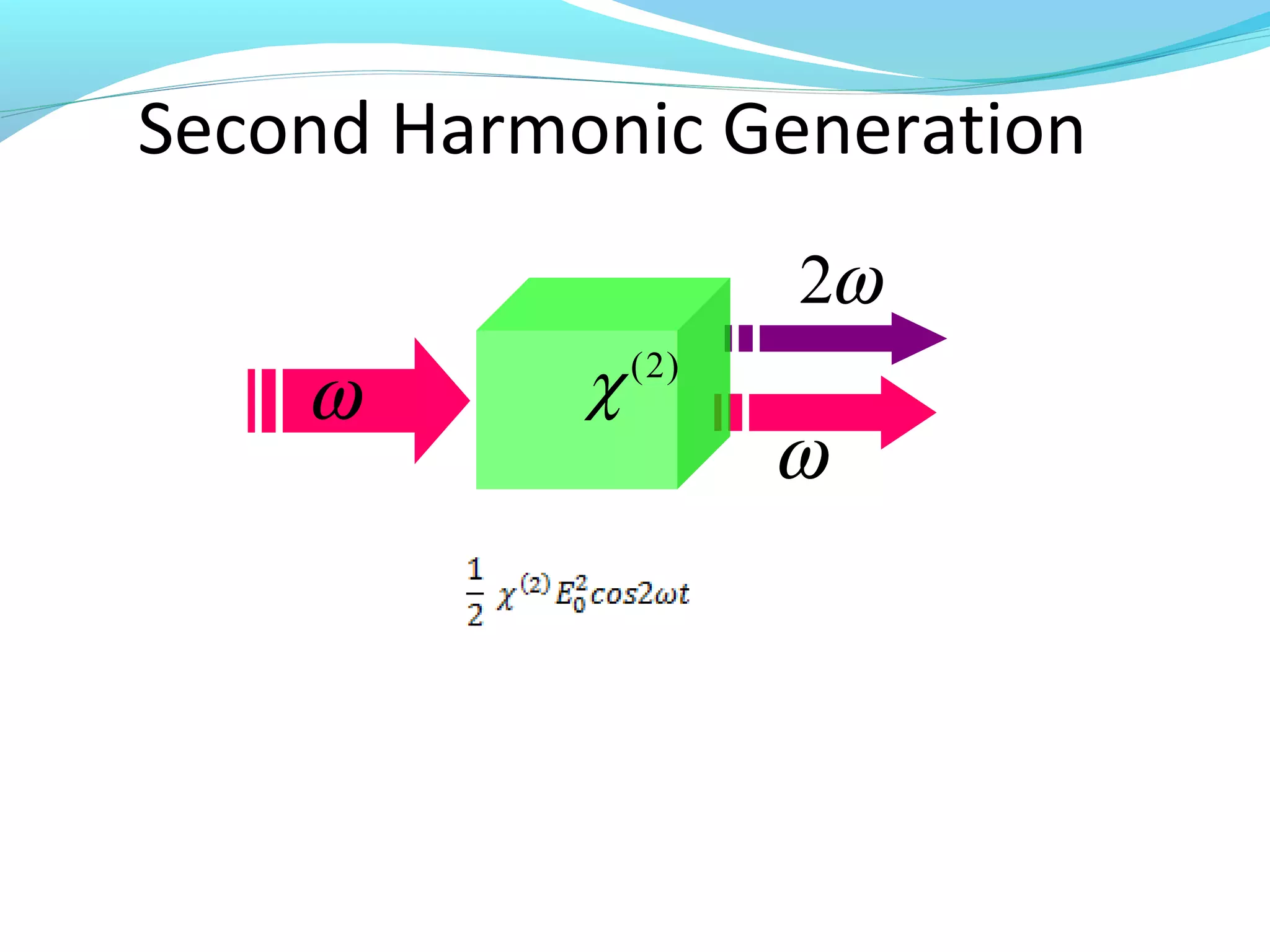
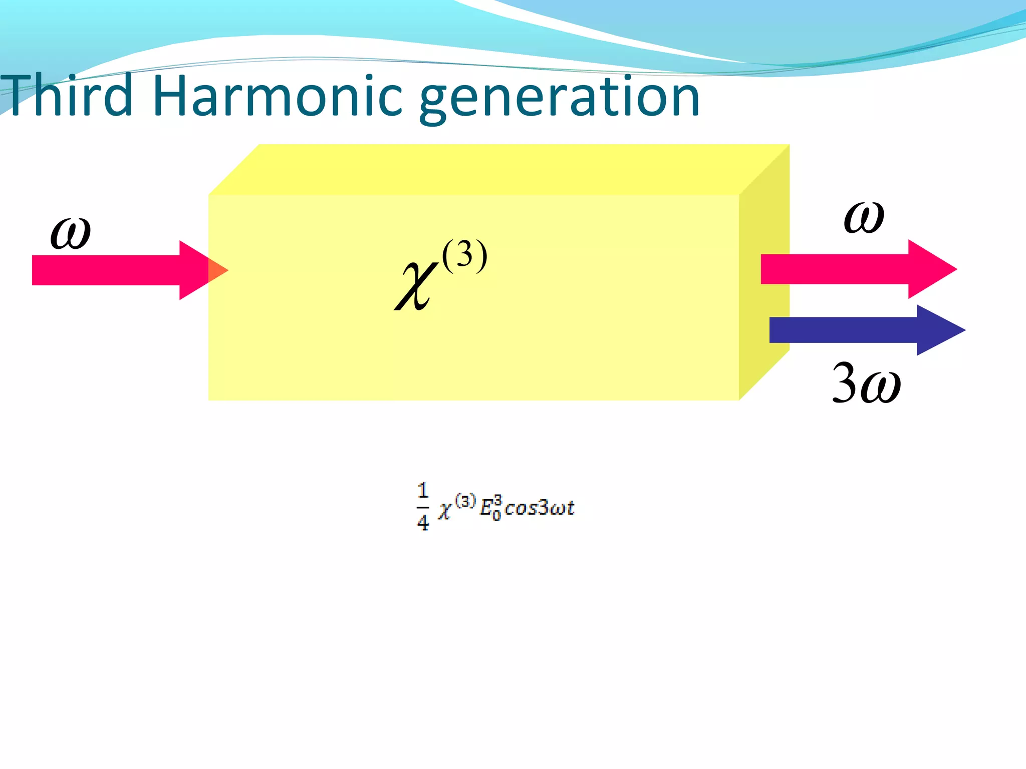
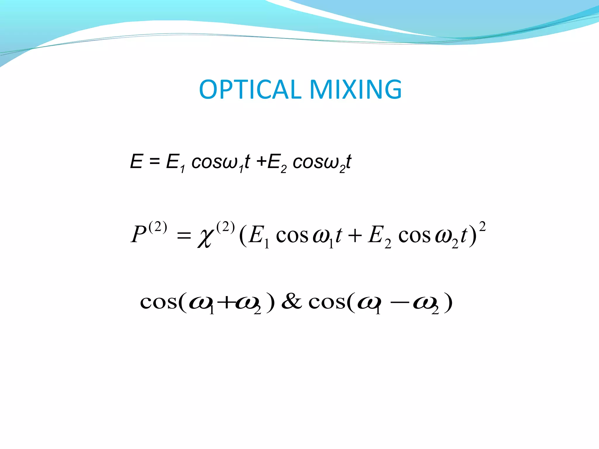
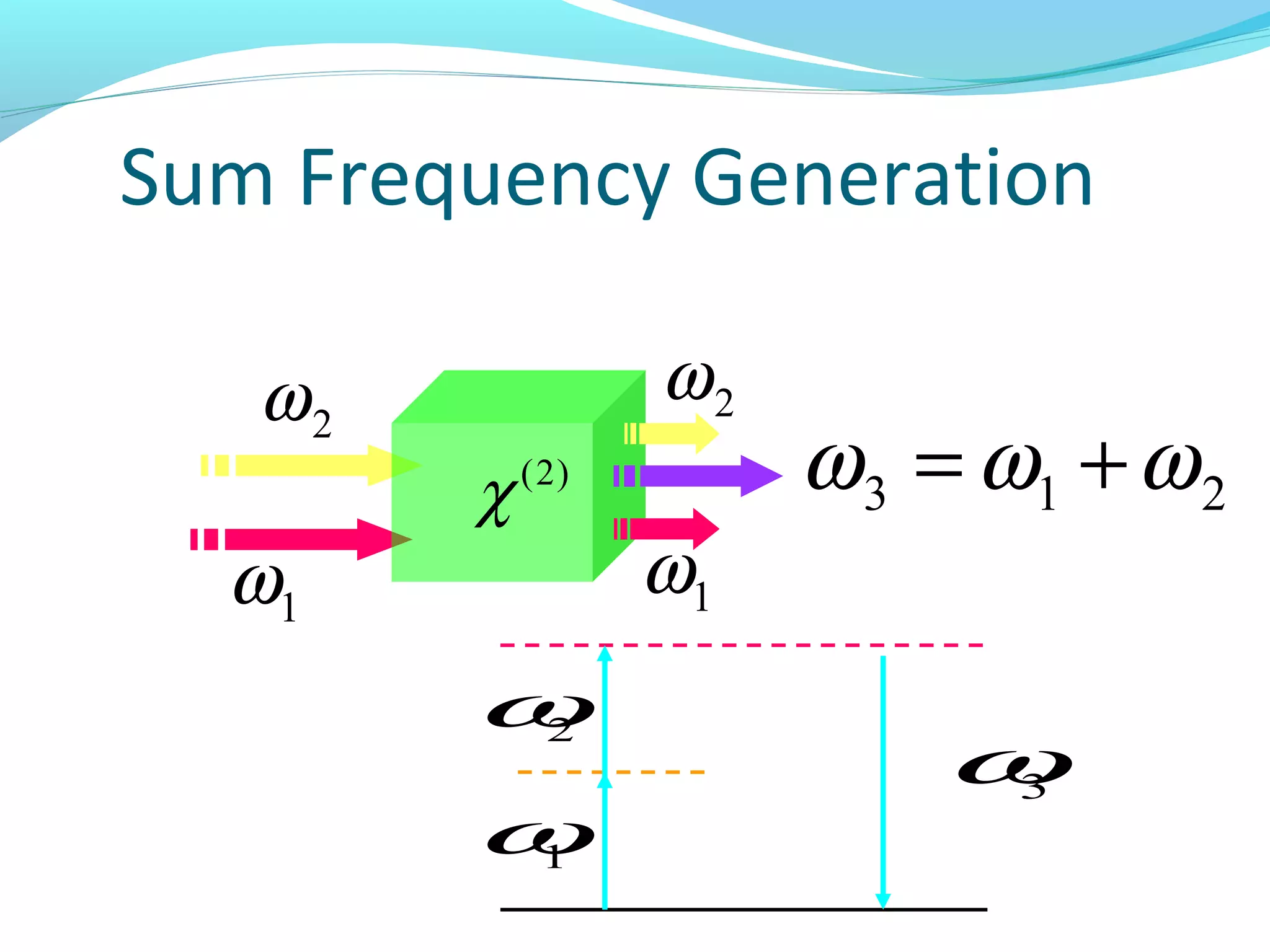
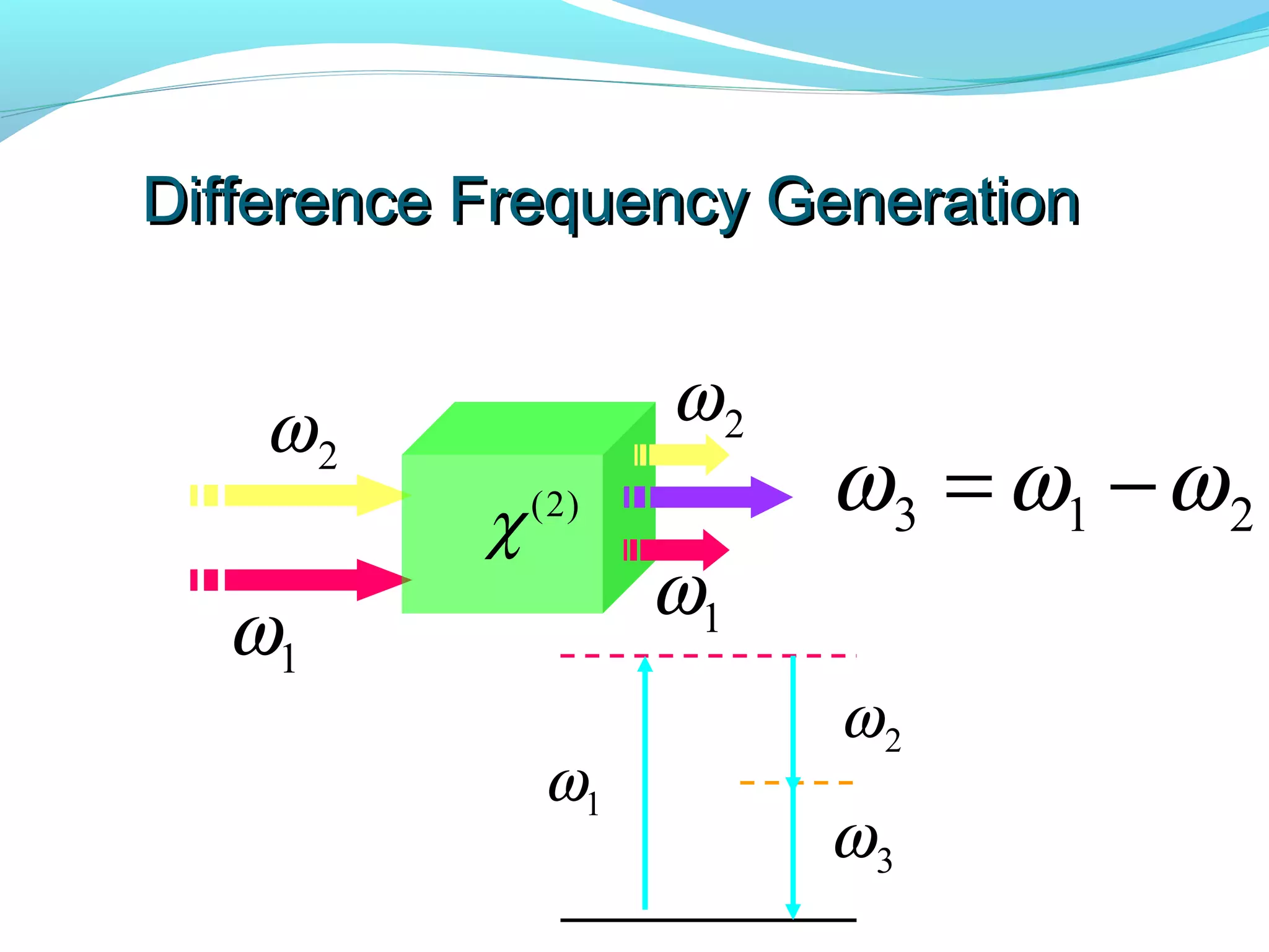
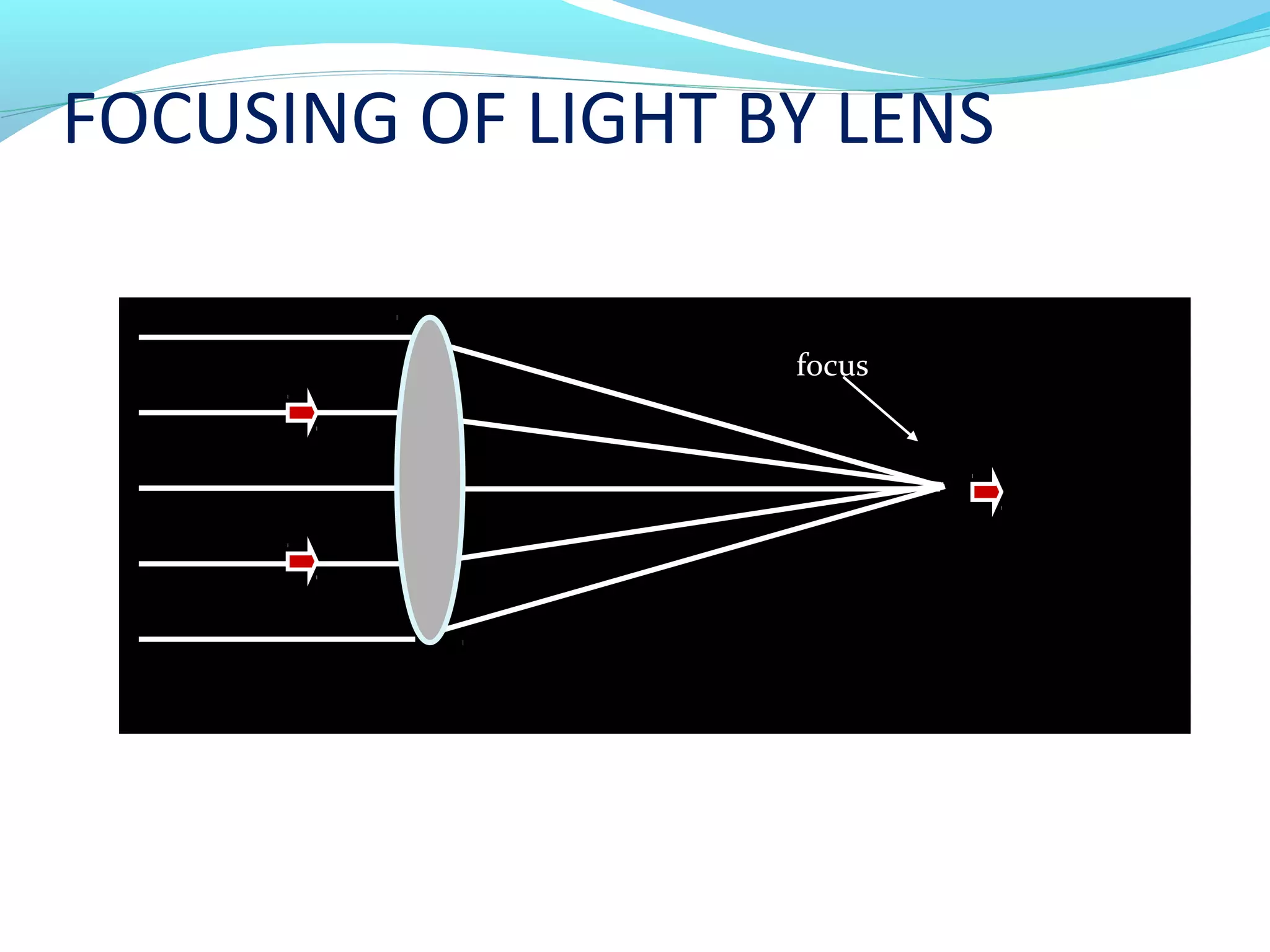
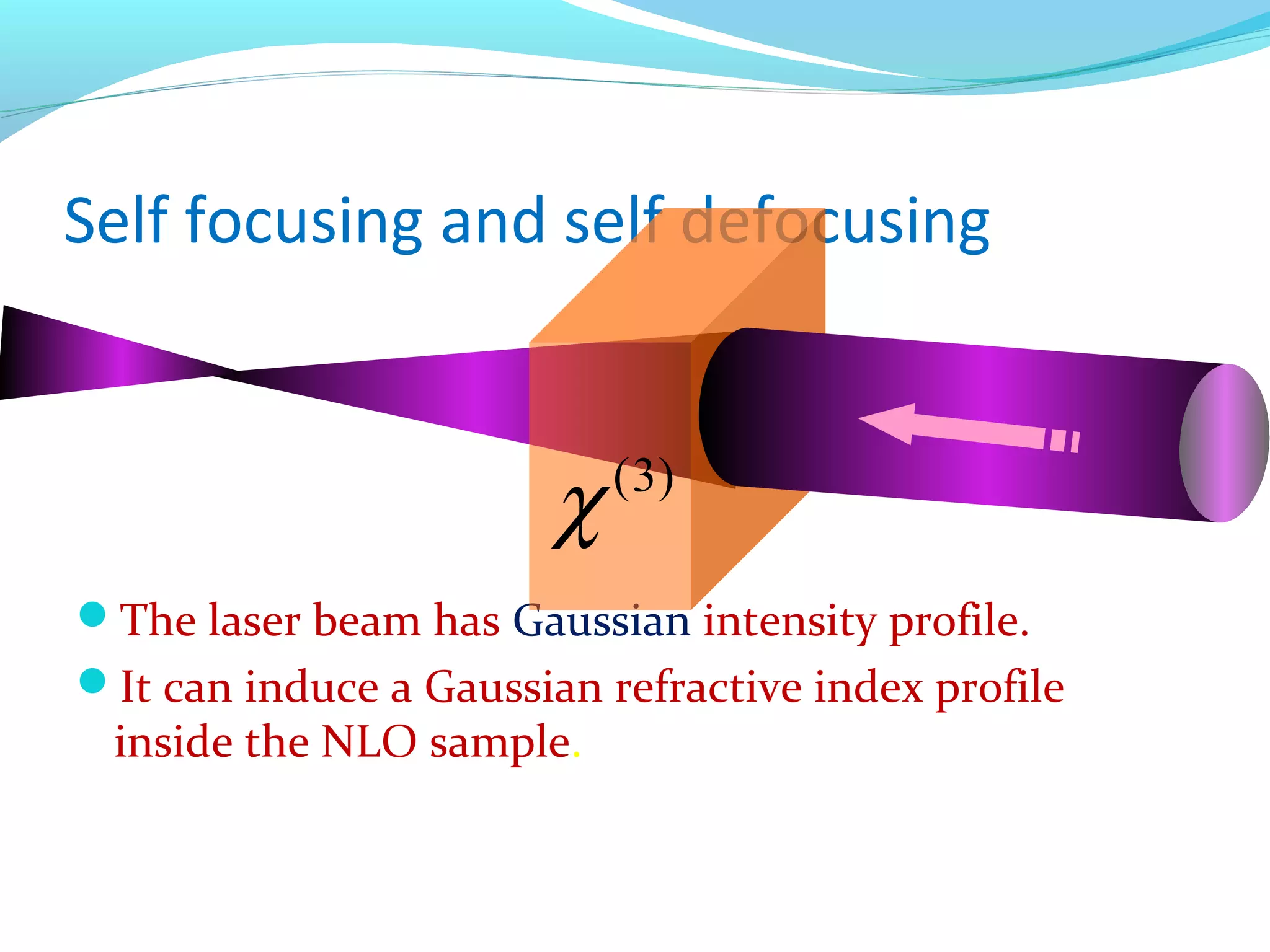
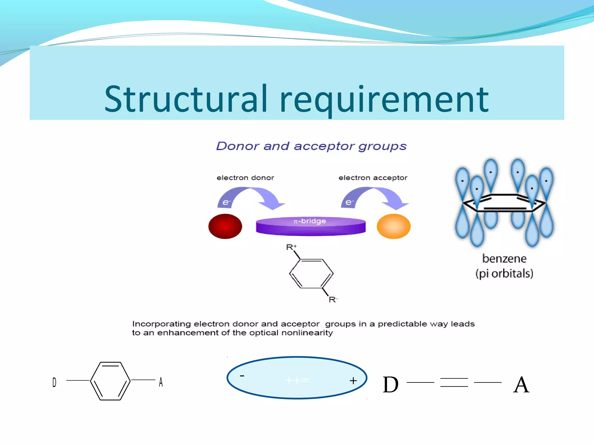
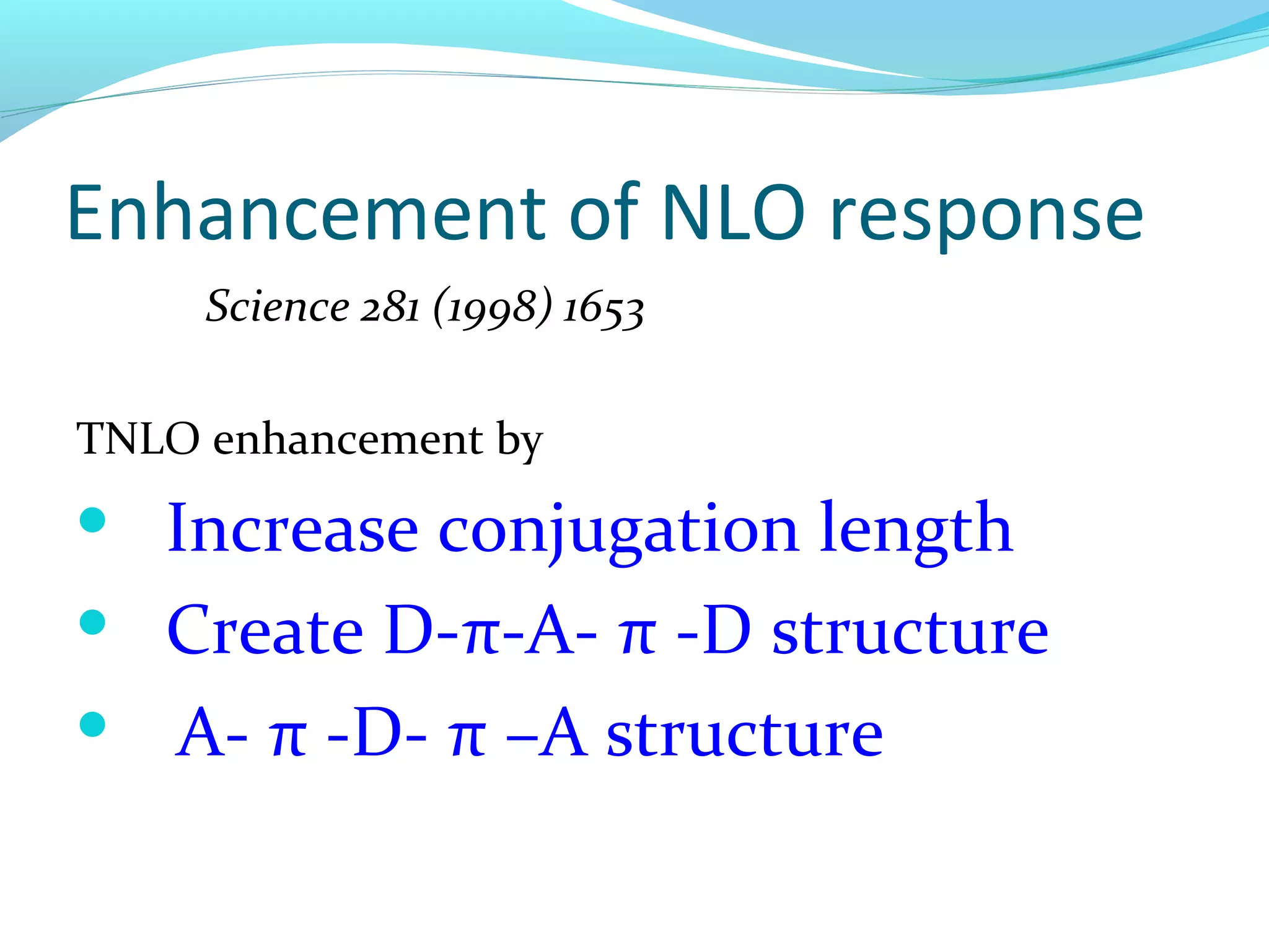
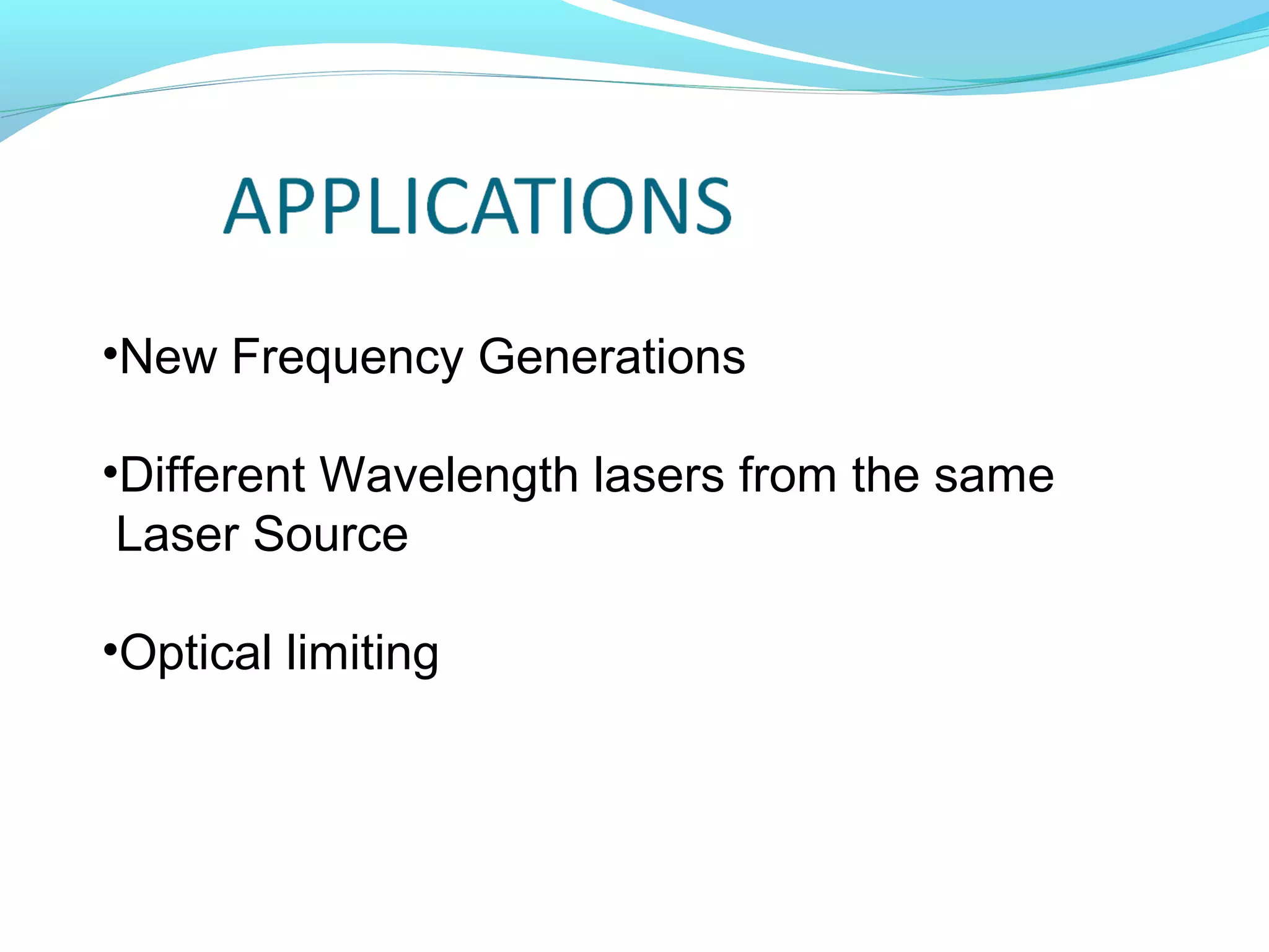
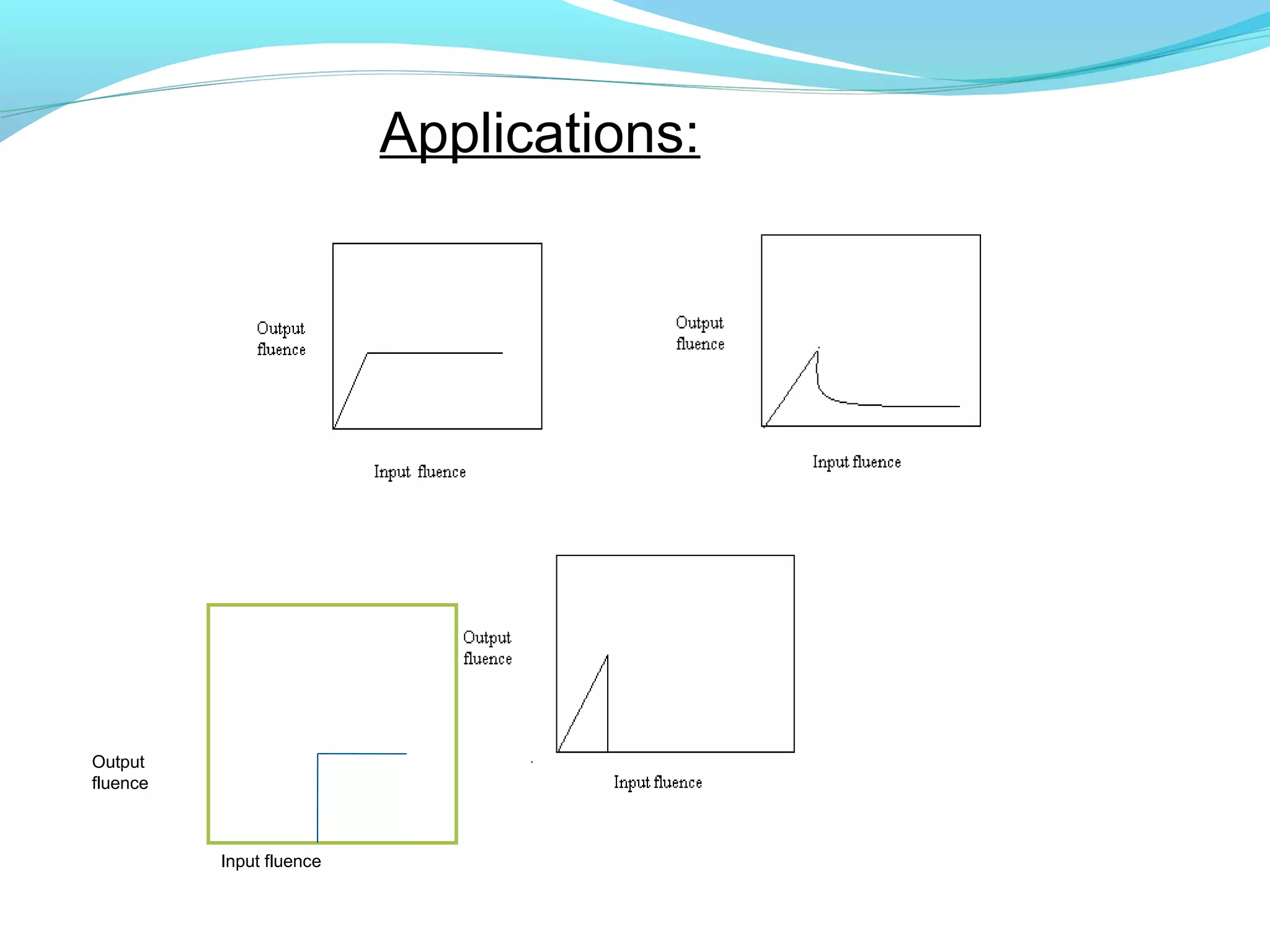

This document compares and contrasts linear and nonlinear optics. In linear optics, light propagates through a medium without changing frequency, while in nonlinear optics the medium's response depends on light intensity. Nonlinear optics involves effects where the induced polarization in a medium does not linearly depend on the electric field of the light. This allows frequency conversion via processes like second harmonic generation and sum frequency generation. Materials can exhibit a nonlinear refractive index, leading to self-focusing or defocusing of high intensity light beams. Nonlinear optical effects enable applications like frequency conversion, optical limiting, and all-optical signal processing.