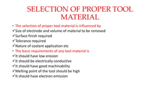
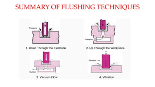
UNIT III
DIELECTRIC AND TOOL MATERIAL
BY
Dr. A. Asha, Professor/Mechanical Engineering
Kamaraj College of Engineering & Technology, Madurai 625701
DIELECTRIC FLUID
A dielectric is a medium that does not conduct electricity. It should not be
hazardous to operators or corrosive to equipment.
In EDM, material removal mainly occurs due to thermal evaporation and melting.
As thermal processing is required to be carried out in absence of oxygen so that the
process can be controlled and oxidation avoided.
Oxidation often leads to poor surface conductivity (electrical) of the workpiece
hindering further machining.
Hence, dielectric fluid should provide an oxygen free machining environment.
Further it should have enough strong dielectric resistance so that it does not
breakdown electrically too easily.
But at the same time, it should ionize when electrons collide with its molecule.
Moreover, during sparking it should be thermally resistant as well.
Generally kerosene and deionised water is used as dielectric fluid in EDM.
DIELECTRIC FLUID
 Tap water cannot be used as it ionises too early and thus breakdown due to presence of
salts as impurities occur.
 Dielectric medium is generally flushed around the spark zone.
 It is also applied through the tool to achieve efficient removal of molten material.
 Three important functions of a dielectric medium in EDM:
1.Insulates the gap between the tool and work, thus preventing a spark to form until the
gap voltage are correct.
2.Cools the electrode, workpiece and solidifies the molten metal particles.
3.Flushes the metal particles out of the working gap to maintain ideal cutting
conditions, increase metal removal rate.
4.It remains electrically non conducting until the required breakdown voltage has been
reached.
 It must be filtered and circulated at constant pressure.
DIELECTRIC FLUID
The main requirements of the EDM dielectric fluids are adequate viscosity, high
flash point, good oxidation stability, minimum odor, low cost, and good electrical
discharge efficiency.
For most EDM operations kerosene is used with certain additives that prevent gas
bubbles and de-odoring.
Silicon fluids and a mixture of these fluids with petroleum oils have given
excellent results.
Other dielectric fluids with a varying degree of success include aqueous solutions
of ethylene glycol, water in emulsions, and distilled water.
TOOL MATERIALS
 Electrode material should be such that it would not undergo much tool wear when it is
impinged by positive ions.
 Thus the localised temperature rise has to be less by properly choosing its properties or
even when temperature increases, there would be less melting.
 Further, the tool should be easily workable as intricate shaped geometric features are
machined in EDM.
 Thus the basic characteristics of electrode materials are:
 High electrical conductivity – electrons are cold emitted more easily and there is less
bulk electrical heating
 High thermal conductivity – for the same heat load, the local temperature rise would
be less due to faster heat conducted to the bulk of the tool and thus less tool wear.
TOOL MATERIALS
 Higher density – for less tool wear and thus less dimensional loss or inaccuracy of
tool
 High melting point – high melting point leads to less tool wear due to less tool
material melting for the same heat load
 Easy manufacturability
 Cost – cheap
 The followings are the different electrode materials which are used commonly in the
industry:
 Graphite
 Electrolytic oxygen free copper
 Tellurium copper – 99% Cu + 0.5% tellurium
 Brass
TOOL MATERIALS
• Graphite :
Generally used as tool material. A wide range of grades are available in
graphite.
Big advantage of graphite is though it is an abrasive it can be easily
produced by several methods like machining, moulding, milling and
grinding etc.
They have better metal removal rates and fine surface finishes than
metallic tool materials.
One disadvantage of copper is it is costlier than copper.
• Copper :
• It can be produced by casting
• Copper tools with very complex features are formed by chemical etching or electro
forming.
• It is generally used for better finishes in the range of Ra = 0.5 μm.
• Copper tungsten:
• The tool material is difficult to machine and it has low metal removal rate. It is costlier
than graphite and copper.
• Copper tungsten and silver tungsten are used for making deep slots under poor flushing
conditions especially in tungsten carbides.
• It has better electrical conductivity than graphite while the corner wear is higher.
• Brass :
• Brass ensures stable sparking conditions and is normally used for specialized applications
such as drilling of small holes where the high electrode wear is acceptable.
TOOL MATERIALS
SELECTION OF PROPER TOOL
MATERIAL
• The selection of proper tool material is influenced by
Size of electrode and volume of material to be removed
Surface finish required
Tolerance required
Nature of coolant application etc
• The basic requirements of any tool material is
It should have low erosion
It should be electrically conductive
It should have good machinability
Melting point of the tool should be high
It should have electron emission
10
EDM – Electrode Wear
 Graphite has shown a low tendency to wear and has the possibility of being molded or machined into
complicated electrode shapes.
 The wear rate of the electrode tool material (Wt) and the wear ratio (Rw) are given by Kalpakjian
(1997).
MRR AND SURFACE FINISH
• MRR : It depends upon the current density and it increases with
current. But high removal rate produces poor finish.
• Therefore the usual practice in EDM is a roughing cut with a
heavy current followed by a finishing cut with less current.
• MRR upto 80mm3/s can be achieved and surface finishes of 0.25
µm can be obtained at very low cutting rates.
• The MRR varies inversely with melting point of the metal
𝑀𝑅𝑅 =
2.44
(𝑀𝐸𝐿𝑇𝐼𝑁𝐺 𝑃𝑂𝐼𝑁𝑇 𝐼𝑁 °𝐶)1.25
• Tolerances of the order of ± 0.05 to 0.13 mm are commonly achieved by
EDM in normal production and with extra care tolerances of ± 0.003 to
0.013mm are possible
FACTORS AFFECTING THE MRR
• MRR increases with forced circulation of dielectric fluid
• It increases with capacitance
• It increases upto optimum value of work tool gap after
then it drops suddenly.
• It increases upto optimum value of spark discharge time
after that it decreases
• MRR is maximum when the pressure is below the
atmospheric pressure
FLUSHING OF DIELECTRIC FLUID
• Flushing refers to proper circulation of dielectric fluid at the gap
between the work and electrode tool in EDM.
• The efficiency of the cutting process depends on the flushing of the
dielectric fluid.
• As the machining progresses the dielectric fluid gets contaminated
with eroded metal particles and carbon particles resulting in the
cracking of dielectric fluid due to heat
• The contamination of fluid reduces its insulation strength leading to
early discharge of the spark.
• If the contamination becomes more than the permitted level bridges
are formed in the gap between the tool and the workpiece creating
short circuit, which damages the tool and workpiece.
• Proper flushing eliminates the bridges in the gap
TYPES OF FLUSHING
•Pressure Flushing
•Reverse Flushing
•Suction Flushing
•Jet Flushing
•Vibration Flushing
PRESSURE FLUSHING
• The fluid is forced through the holes in the electrode to pass through
the gap between the tool and work piece.
• The fluid under pressure flushes the solid particles and cools the tool
and the work.
• In the electrode hole a needle like work material will be left off. This is
removed to get a clean surface
REVERSE FLUSHING
• Particularly useful in machining deep cavity dies, where the taper
produced using the normal flow mode can be reduced.
• The gap is submerged in filtered dielectric, and instead of pressure
being applied at the source a vacuum is used.
• With clean fluid flowing between the work piece and the tool, there is
no side sparking and, therefore, no taper is produced.
SUCTION FLUSHING
• The dielectric fluid circulated is removed by using a vacuum pump
• Vacuum is created using a vacuum pump which in turn sucks the
dielectric fluid present in the gap between the tool and work.
• In this process also needle like work material is left, which is removed
later for smooth surface.
JET FLUSHING
• In jet flushing the dielectric fluid is fed into the gap between the tool
and the work using the nozzle.
• This flushes away the debris removed while metal removal.
• This method is found to be less effective and it is used only when
none of the other methods can be used.
VIBRATION FLUSHING
• The tool is vibrated to provide flushing action of the dielectric fluid
• This method is used for small tools that cannot accommodate the
fluid passage for the flow of the dielectric fluid.
• This method is used for drilling deep holes of small diameter
SUMMARY OF FLUSHING TECHNIQUES
SPARK GENERATING CIRCUITS
• Relaxation circuit
• Direct current flows through the resistor and
charges the capacitor.
• When the capacitor voltage reaches between
50 to 250 V the dielectric medium breaks
down.
• The dielectric ionizes and millions of
electrons are generated by creating a spark
between the gap of the tool and electrode.
• During sparking the voltage falls and it again
starts rising and the process is repeated.
R-C-L CIRCUIT
• In the relaxation circuit the metal
removal rate increases when the R
decreases.
• R cannot be decreased beyond the
critical value
• If decreased beyond the critical value
the arc produces instead of spark.
• The capacitor charging time also
increases.
• So an inductance is included in the
charging circuit.
ROTARY PULSE GENERATOR
• The R-C and R-C-L circuit yield low
metal removal rate.
• In this circuit the capacitor is charged
through the diode during the first half
of the cycle.
• During the next half of the cycle the
sum of voltages generated by the
capacitor and generator is applied to
the work and tool gap.
• This results in more MRR but the
surface finish is poor.
CONTROLLED PULSE GENERATOR
CIRCUIT
• In the above circuits discussed there is no
provision for an automatic prevention of the
current flow when a short circuit is
developed.
• To achieve an automatic control a vacuum
tube is used as the switching device.
• During sparking the current which flows
through the gap comes from the capacitor.
• When the current flows through the gap the
valve tube is biased to cut off and and
behaves like an infinite resistance. The bias
control is done through an electronic control.
• As soon as the current in the gap ceases the
conductivity of the tube increases allowing
the flow of current to charge the capacitor for
the next cycle
WIRE CUT EDM MACHINE
• A very thin wire 0.02 to 0.3 mm made of brass
or molybdenum having circular cross section is
used as a electrode
• The wire is stretched between two rollers and
the part of the wire is eroded by spark
• The prominent feature is that the complicated
cut can be easily machined without using an
electrode
• It consists of
a. workpiece control unit
b. workpiece mounting table
c. dielectric supply unit
d. Power supply unit
e. Wire drive section
WORKING OF WEDM MACHINE
• Work piece to be machined is
mounted on the table.
• A very small hole is predrilled in the
work piece through which a very thin
wire made of brass or molybdenum is
passed
• Dielectric fluid (distilled water) is
passed over the work piece and wire
using the pump
• When the DC supply is given to the
circuit and when it reaches the
required voltage spark is produced
across the gap
• The spark occurs at an interval of 10
to 30 microseconds with a current
density of 15-500A/mm2.
• So thousands of spark discharge
occurs per second which results in an
increase in temperature of 100000C.
• At this high temperature the work
piece metal is melted, eroded and
some of it is vaporized.
• The metal is thus removed from the
work piece
• The removed fine material particles
are carried away by dielectric fluid
circulated around it
ADVANTAGES OF WEDM PROCESS
1. Manufacturing electrode: In this process a very thin brass wire or
molybdenum is used as an electrode to machine the work piece.
There is no need to manufacture the electrode
2. Electrode wear: During the machining process the wire electrode is
constantly fed into the workpiece. So the wear of the tool is
practically ignored.
3. Surface finishing : A very thin wire electrode is constantly fed into
the work piece at a speed of about 10-30mm/s by wire feed
mechanism. Machining is continuous without the formation of
chips and gases. This gives high surface finish and reduces manual
finishing time.
4. Complicated Shapes : By using the programme very minute shapes
can be efficiently machined. So there is no need of skilled
operators.
ADVANTAGES OF WEDM PROCESS
5. Time utilization :Since all the motion of the machines of the EDM process are
controlled by NC hence it can be operated throughout the day without any fire hazards
6. Straight holes : The electrode wire is maintained is optimum tension by a tension
control mechanism. It prevents wire breakage and wire vibration.
7. Rejection : Rejection of material is minimized due to initial planning and checking the
programme
8. Economical : since most of the programming can be easily done it is economical for
small batch production.
9. Cycle Time : Cycle time is shorter
10. Inspection Time : Inspection time is reduced due to high positioning accuracy
Disadvantages :
Capital cost is high, Cutting rate is slow, Not suitable for large workpieces
Applications :
Best suited for the production of gears, tools, dies, rotors, turbine blades and cams
for small and medium size batch production

Dielectric

  • 1.
    UNIT III DIELECTRIC ANDTOOL MATERIAL BY Dr. A. Asha, Professor/Mechanical Engineering Kamaraj College of Engineering & Technology, Madurai 625701
  • 2.
    DIELECTRIC FLUID A dielectricis a medium that does not conduct electricity. It should not be hazardous to operators or corrosive to equipment. In EDM, material removal mainly occurs due to thermal evaporation and melting. As thermal processing is required to be carried out in absence of oxygen so that the process can be controlled and oxidation avoided. Oxidation often leads to poor surface conductivity (electrical) of the workpiece hindering further machining. Hence, dielectric fluid should provide an oxygen free machining environment. Further it should have enough strong dielectric resistance so that it does not breakdown electrically too easily. But at the same time, it should ionize when electrons collide with its molecule. Moreover, during sparking it should be thermally resistant as well. Generally kerosene and deionised water is used as dielectric fluid in EDM.
  • 3.
    DIELECTRIC FLUID  Tapwater cannot be used as it ionises too early and thus breakdown due to presence of salts as impurities occur.  Dielectric medium is generally flushed around the spark zone.  It is also applied through the tool to achieve efficient removal of molten material.  Three important functions of a dielectric medium in EDM: 1.Insulates the gap between the tool and work, thus preventing a spark to form until the gap voltage are correct. 2.Cools the electrode, workpiece and solidifies the molten metal particles. 3.Flushes the metal particles out of the working gap to maintain ideal cutting conditions, increase metal removal rate. 4.It remains electrically non conducting until the required breakdown voltage has been reached.  It must be filtered and circulated at constant pressure.
  • 4.
    DIELECTRIC FLUID The mainrequirements of the EDM dielectric fluids are adequate viscosity, high flash point, good oxidation stability, minimum odor, low cost, and good electrical discharge efficiency. For most EDM operations kerosene is used with certain additives that prevent gas bubbles and de-odoring. Silicon fluids and a mixture of these fluids with petroleum oils have given excellent results. Other dielectric fluids with a varying degree of success include aqueous solutions of ethylene glycol, water in emulsions, and distilled water.
  • 5.
    TOOL MATERIALS  Electrodematerial should be such that it would not undergo much tool wear when it is impinged by positive ions.  Thus the localised temperature rise has to be less by properly choosing its properties or even when temperature increases, there would be less melting.  Further, the tool should be easily workable as intricate shaped geometric features are machined in EDM.  Thus the basic characteristics of electrode materials are:  High electrical conductivity – electrons are cold emitted more easily and there is less bulk electrical heating  High thermal conductivity – for the same heat load, the local temperature rise would be less due to faster heat conducted to the bulk of the tool and thus less tool wear.
  • 6.
    TOOL MATERIALS  Higherdensity – for less tool wear and thus less dimensional loss or inaccuracy of tool  High melting point – high melting point leads to less tool wear due to less tool material melting for the same heat load  Easy manufacturability  Cost – cheap  The followings are the different electrode materials which are used commonly in the industry:  Graphite  Electrolytic oxygen free copper  Tellurium copper – 99% Cu + 0.5% tellurium  Brass
  • 7.
    TOOL MATERIALS • Graphite: Generally used as tool material. A wide range of grades are available in graphite. Big advantage of graphite is though it is an abrasive it can be easily produced by several methods like machining, moulding, milling and grinding etc. They have better metal removal rates and fine surface finishes than metallic tool materials. One disadvantage of copper is it is costlier than copper.
  • 8.
    • Copper : •It can be produced by casting • Copper tools with very complex features are formed by chemical etching or electro forming. • It is generally used for better finishes in the range of Ra = 0.5 μm. • Copper tungsten: • The tool material is difficult to machine and it has low metal removal rate. It is costlier than graphite and copper. • Copper tungsten and silver tungsten are used for making deep slots under poor flushing conditions especially in tungsten carbides. • It has better electrical conductivity than graphite while the corner wear is higher. • Brass : • Brass ensures stable sparking conditions and is normally used for specialized applications such as drilling of small holes where the high electrode wear is acceptable. TOOL MATERIALS
  • 9.
    SELECTION OF PROPERTOOL MATERIAL • The selection of proper tool material is influenced by Size of electrode and volume of material to be removed Surface finish required Tolerance required Nature of coolant application etc • The basic requirements of any tool material is It should have low erosion It should be electrically conductive It should have good machinability Melting point of the tool should be high It should have electron emission
  • 10.
  • 11.
  • 12.
    EDM – ElectrodeWear  Graphite has shown a low tendency to wear and has the possibility of being molded or machined into complicated electrode shapes.  The wear rate of the electrode tool material (Wt) and the wear ratio (Rw) are given by Kalpakjian (1997).
  • 13.
    MRR AND SURFACEFINISH • MRR : It depends upon the current density and it increases with current. But high removal rate produces poor finish. • Therefore the usual practice in EDM is a roughing cut with a heavy current followed by a finishing cut with less current. • MRR upto 80mm3/s can be achieved and surface finishes of 0.25 µm can be obtained at very low cutting rates. • The MRR varies inversely with melting point of the metal 𝑀𝑅𝑅 = 2.44 (𝑀𝐸𝐿𝑇𝐼𝑁𝐺 𝑃𝑂𝐼𝑁𝑇 𝐼𝑁 °𝐶)1.25 • Tolerances of the order of ± 0.05 to 0.13 mm are commonly achieved by EDM in normal production and with extra care tolerances of ± 0.003 to 0.013mm are possible
  • 14.
    FACTORS AFFECTING THEMRR • MRR increases with forced circulation of dielectric fluid • It increases with capacitance • It increases upto optimum value of work tool gap after then it drops suddenly. • It increases upto optimum value of spark discharge time after that it decreases • MRR is maximum when the pressure is below the atmospheric pressure
  • 15.
    FLUSHING OF DIELECTRICFLUID • Flushing refers to proper circulation of dielectric fluid at the gap between the work and electrode tool in EDM. • The efficiency of the cutting process depends on the flushing of the dielectric fluid. • As the machining progresses the dielectric fluid gets contaminated with eroded metal particles and carbon particles resulting in the cracking of dielectric fluid due to heat • The contamination of fluid reduces its insulation strength leading to early discharge of the spark. • If the contamination becomes more than the permitted level bridges are formed in the gap between the tool and the workpiece creating short circuit, which damages the tool and workpiece. • Proper flushing eliminates the bridges in the gap
  • 16.
    TYPES OF FLUSHING •PressureFlushing •Reverse Flushing •Suction Flushing •Jet Flushing •Vibration Flushing
  • 17.
    PRESSURE FLUSHING • Thefluid is forced through the holes in the electrode to pass through the gap between the tool and work piece. • The fluid under pressure flushes the solid particles and cools the tool and the work. • In the electrode hole a needle like work material will be left off. This is removed to get a clean surface
  • 18.
    REVERSE FLUSHING • Particularlyuseful in machining deep cavity dies, where the taper produced using the normal flow mode can be reduced. • The gap is submerged in filtered dielectric, and instead of pressure being applied at the source a vacuum is used. • With clean fluid flowing between the work piece and the tool, there is no side sparking and, therefore, no taper is produced.
  • 19.
    SUCTION FLUSHING • Thedielectric fluid circulated is removed by using a vacuum pump • Vacuum is created using a vacuum pump which in turn sucks the dielectric fluid present in the gap between the tool and work. • In this process also needle like work material is left, which is removed later for smooth surface.
  • 20.
    JET FLUSHING • Injet flushing the dielectric fluid is fed into the gap between the tool and the work using the nozzle. • This flushes away the debris removed while metal removal. • This method is found to be less effective and it is used only when none of the other methods can be used.
  • 21.
    VIBRATION FLUSHING • Thetool is vibrated to provide flushing action of the dielectric fluid • This method is used for small tools that cannot accommodate the fluid passage for the flow of the dielectric fluid. • This method is used for drilling deep holes of small diameter
  • 22.
  • 23.
    SPARK GENERATING CIRCUITS •Relaxation circuit • Direct current flows through the resistor and charges the capacitor. • When the capacitor voltage reaches between 50 to 250 V the dielectric medium breaks down. • The dielectric ionizes and millions of electrons are generated by creating a spark between the gap of the tool and electrode. • During sparking the voltage falls and it again starts rising and the process is repeated.
  • 24.
    R-C-L CIRCUIT • Inthe relaxation circuit the metal removal rate increases when the R decreases. • R cannot be decreased beyond the critical value • If decreased beyond the critical value the arc produces instead of spark. • The capacitor charging time also increases. • So an inductance is included in the charging circuit.
  • 25.
    ROTARY PULSE GENERATOR •The R-C and R-C-L circuit yield low metal removal rate. • In this circuit the capacitor is charged through the diode during the first half of the cycle. • During the next half of the cycle the sum of voltages generated by the capacitor and generator is applied to the work and tool gap. • This results in more MRR but the surface finish is poor.
  • 26.
    CONTROLLED PULSE GENERATOR CIRCUIT •In the above circuits discussed there is no provision for an automatic prevention of the current flow when a short circuit is developed. • To achieve an automatic control a vacuum tube is used as the switching device. • During sparking the current which flows through the gap comes from the capacitor. • When the current flows through the gap the valve tube is biased to cut off and and behaves like an infinite resistance. The bias control is done through an electronic control. • As soon as the current in the gap ceases the conductivity of the tube increases allowing the flow of current to charge the capacitor for the next cycle
  • 27.
    WIRE CUT EDMMACHINE • A very thin wire 0.02 to 0.3 mm made of brass or molybdenum having circular cross section is used as a electrode • The wire is stretched between two rollers and the part of the wire is eroded by spark • The prominent feature is that the complicated cut can be easily machined without using an electrode • It consists of a. workpiece control unit b. workpiece mounting table c. dielectric supply unit d. Power supply unit e. Wire drive section
  • 28.
    WORKING OF WEDMMACHINE • Work piece to be machined is mounted on the table. • A very small hole is predrilled in the work piece through which a very thin wire made of brass or molybdenum is passed • Dielectric fluid (distilled water) is passed over the work piece and wire using the pump • When the DC supply is given to the circuit and when it reaches the required voltage spark is produced across the gap • The spark occurs at an interval of 10 to 30 microseconds with a current density of 15-500A/mm2. • So thousands of spark discharge occurs per second which results in an increase in temperature of 100000C. • At this high temperature the work piece metal is melted, eroded and some of it is vaporized. • The metal is thus removed from the work piece • The removed fine material particles are carried away by dielectric fluid circulated around it
  • 29.
    ADVANTAGES OF WEDMPROCESS 1. Manufacturing electrode: In this process a very thin brass wire or molybdenum is used as an electrode to machine the work piece. There is no need to manufacture the electrode 2. Electrode wear: During the machining process the wire electrode is constantly fed into the workpiece. So the wear of the tool is practically ignored. 3. Surface finishing : A very thin wire electrode is constantly fed into the work piece at a speed of about 10-30mm/s by wire feed mechanism. Machining is continuous without the formation of chips and gases. This gives high surface finish and reduces manual finishing time. 4. Complicated Shapes : By using the programme very minute shapes can be efficiently machined. So there is no need of skilled operators.
  • 30.
    ADVANTAGES OF WEDMPROCESS 5. Time utilization :Since all the motion of the machines of the EDM process are controlled by NC hence it can be operated throughout the day without any fire hazards 6. Straight holes : The electrode wire is maintained is optimum tension by a tension control mechanism. It prevents wire breakage and wire vibration. 7. Rejection : Rejection of material is minimized due to initial planning and checking the programme 8. Economical : since most of the programming can be easily done it is economical for small batch production. 9. Cycle Time : Cycle time is shorter 10. Inspection Time : Inspection time is reduced due to high positioning accuracy Disadvantages : Capital cost is high, Cutting rate is slow, Not suitable for large workpieces Applications : Best suited for the production of gears, tools, dies, rotors, turbine blades and cams for small and medium size batch production

Editor's Notes