Downloaded 857 times


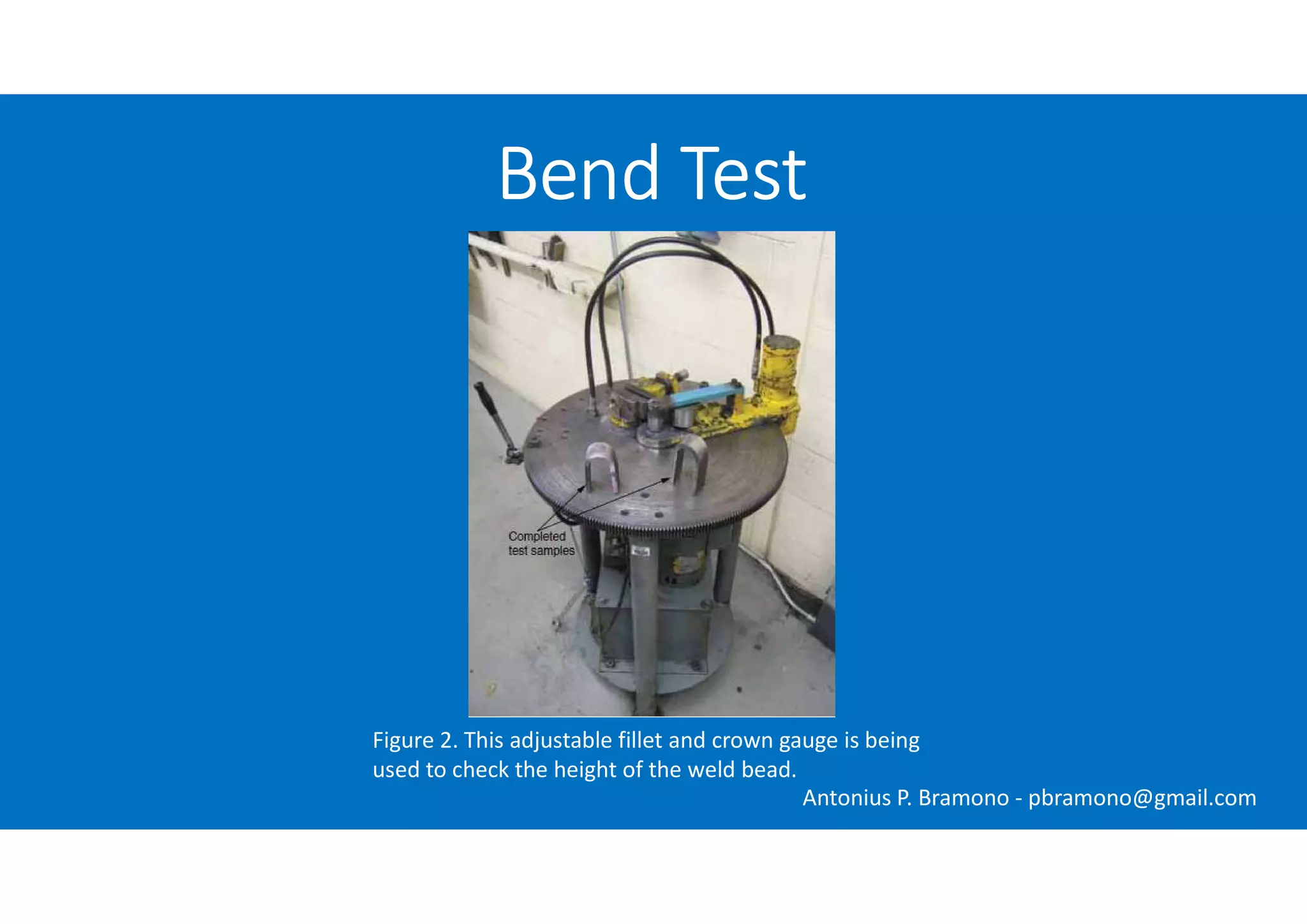
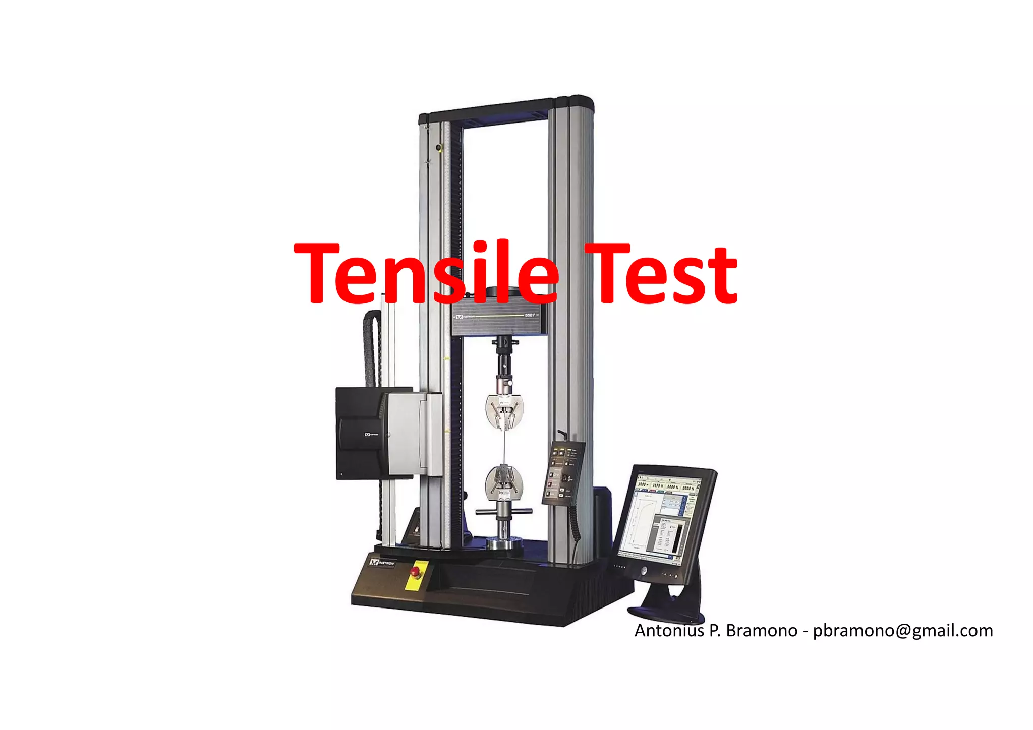
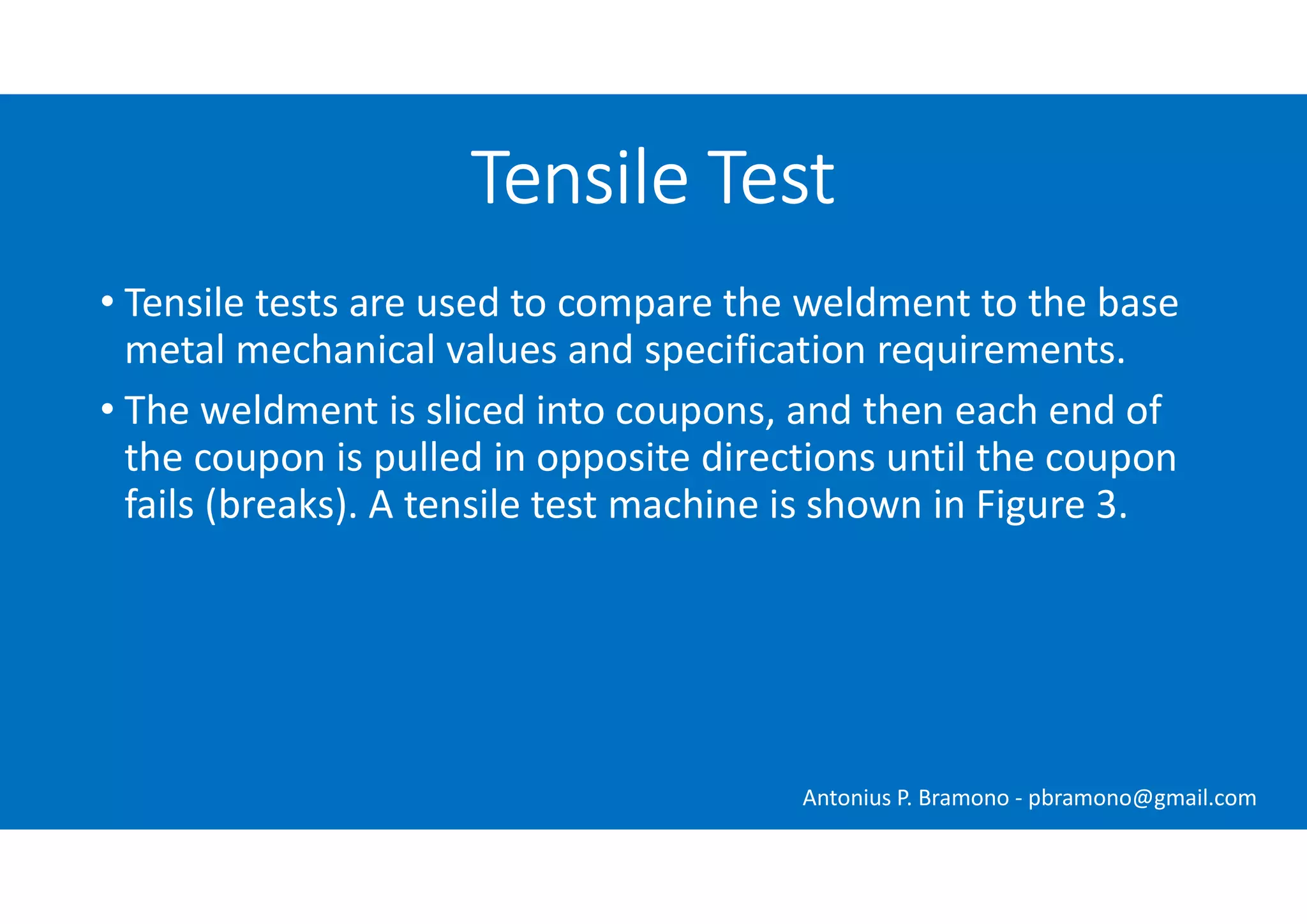
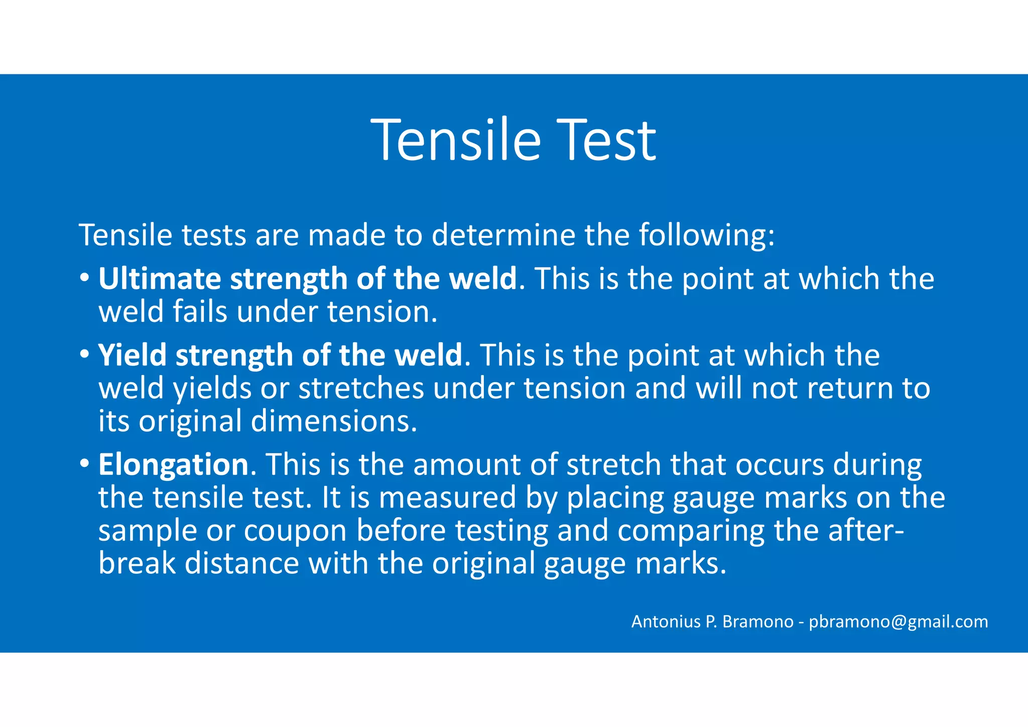
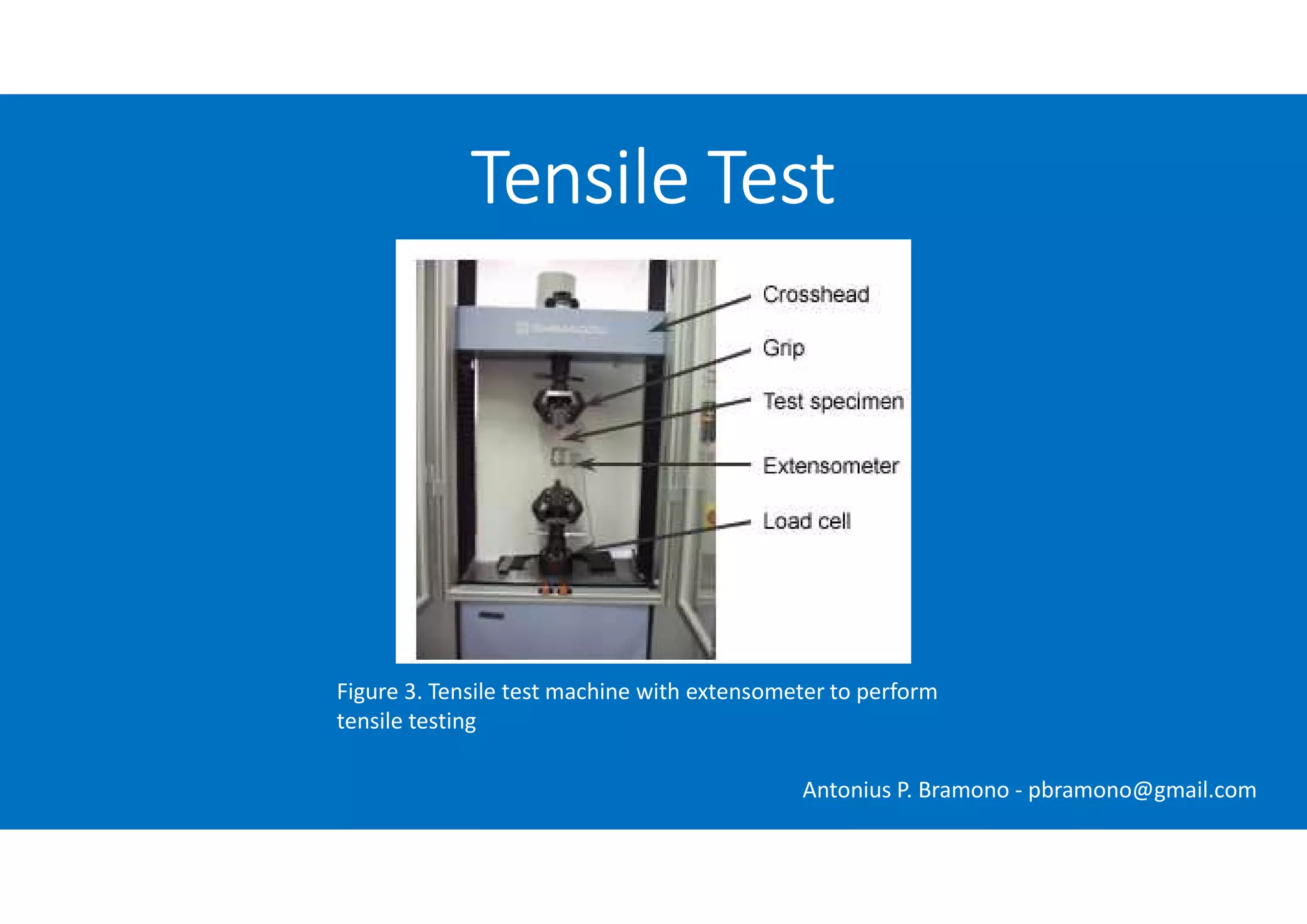
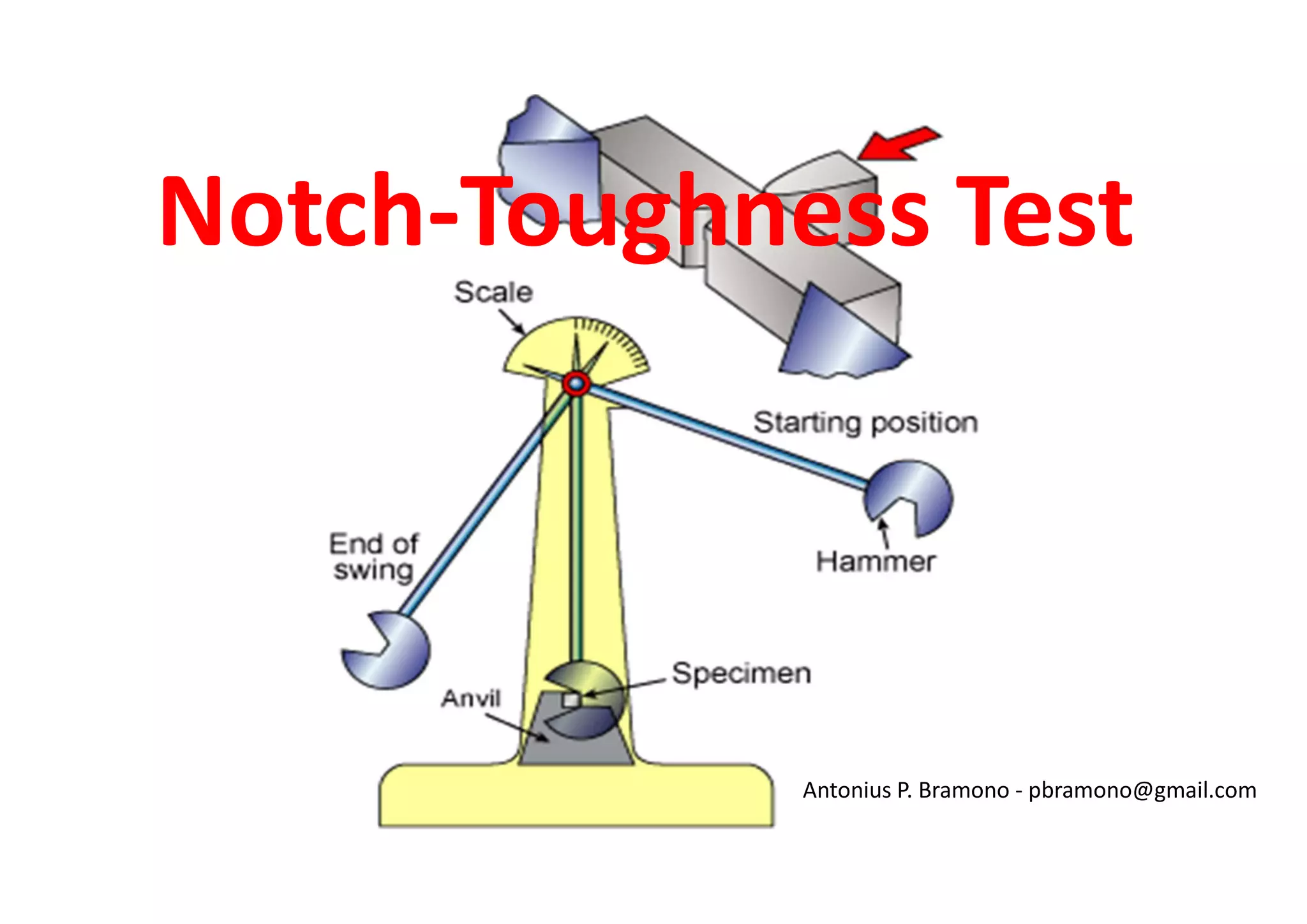
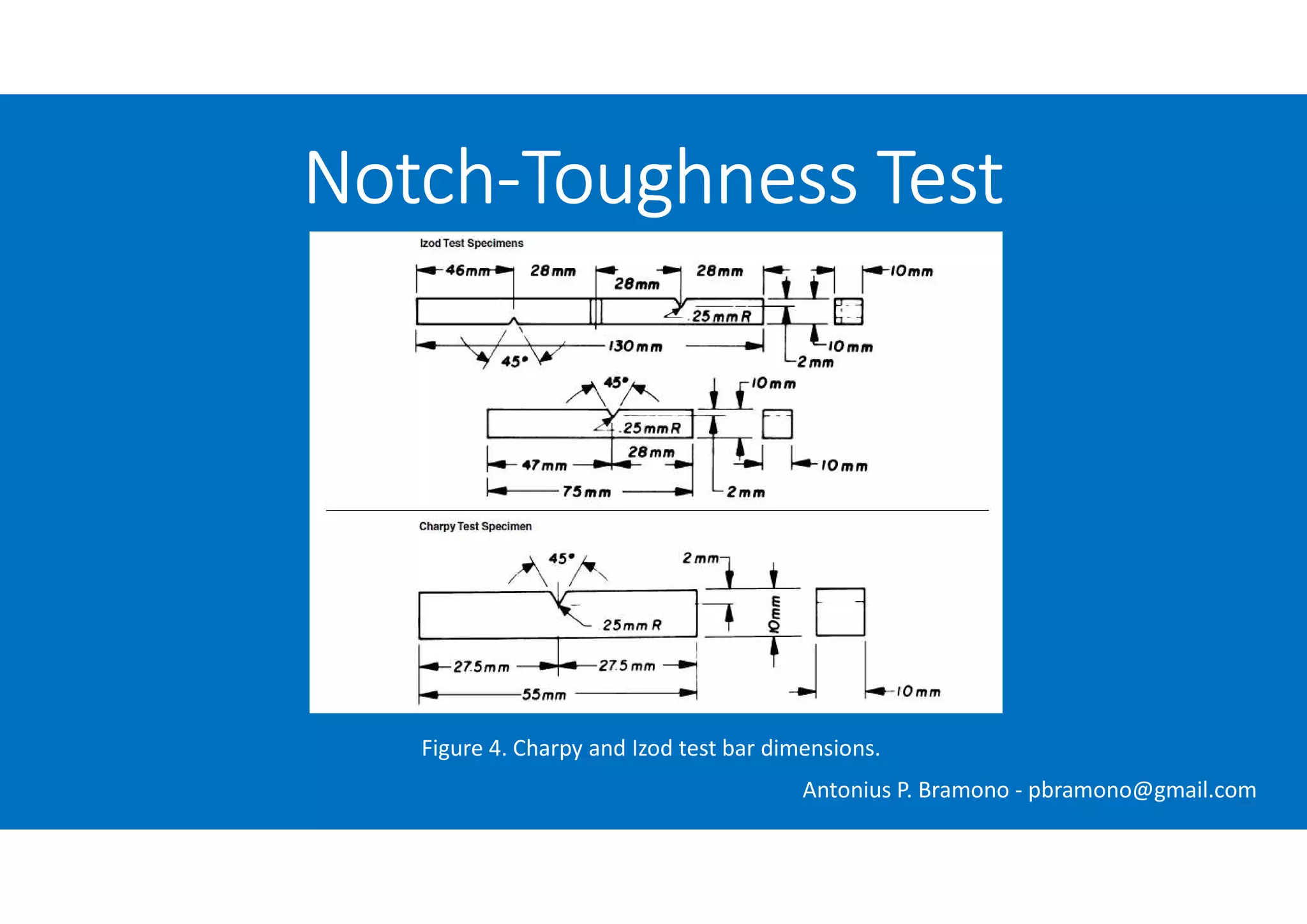
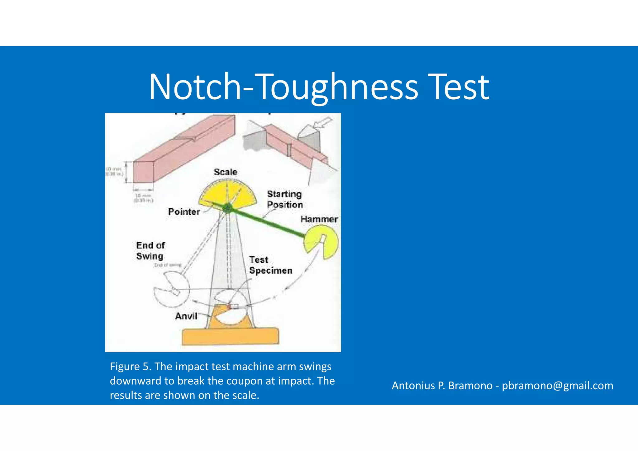
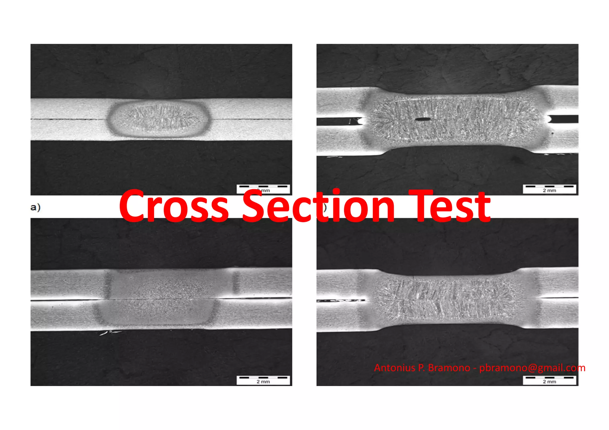
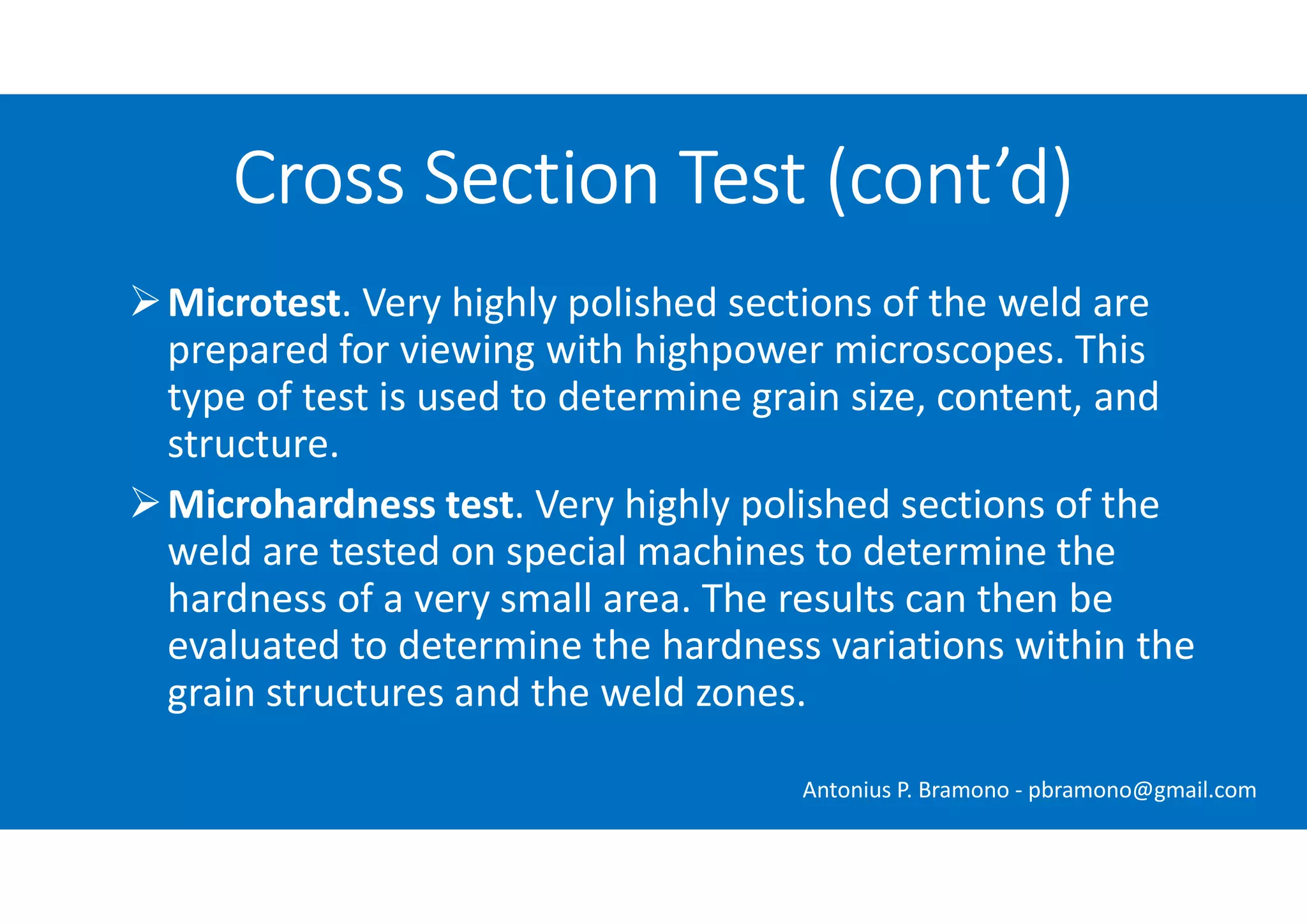
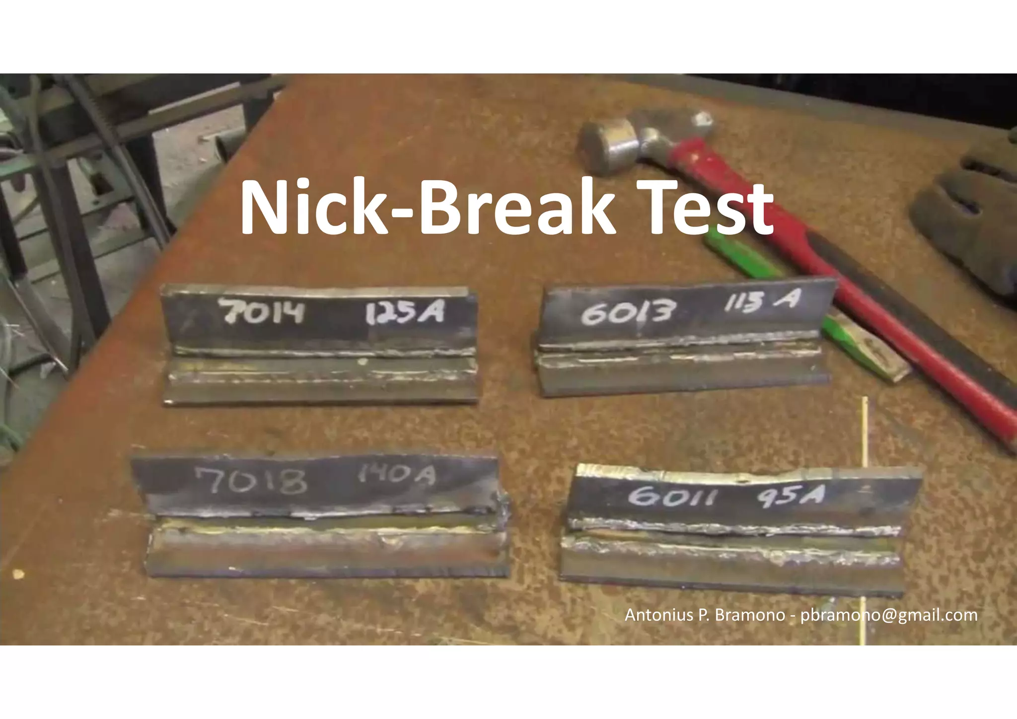

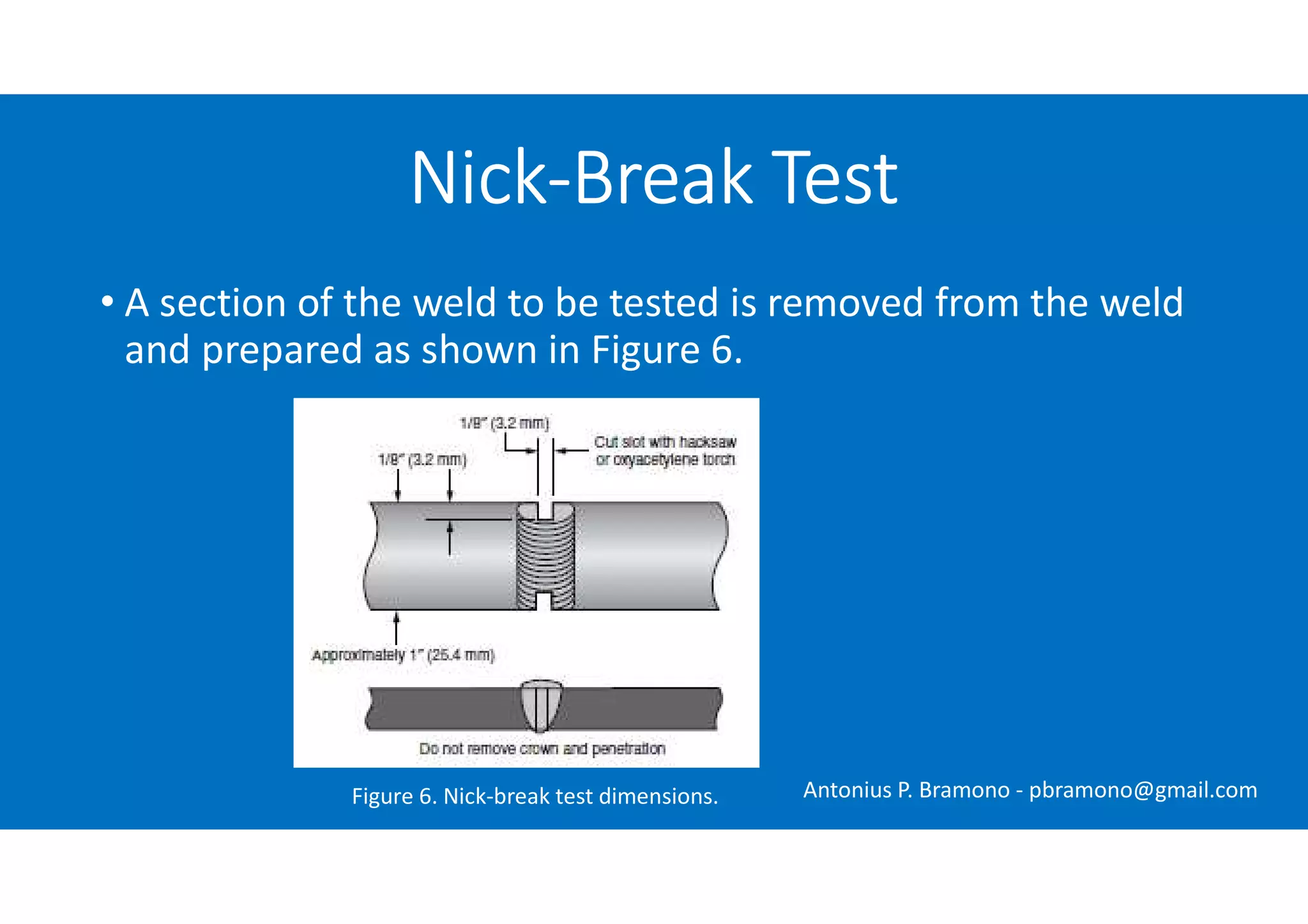
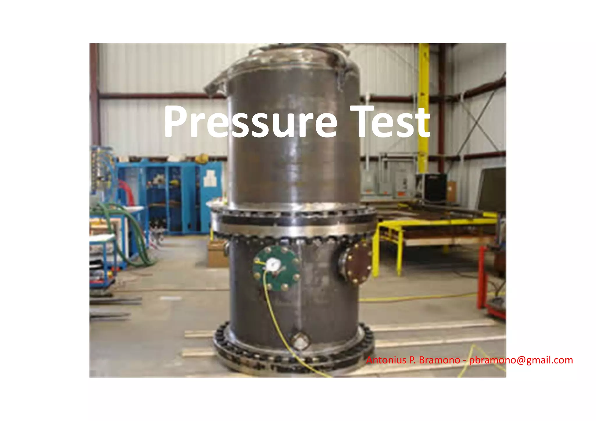

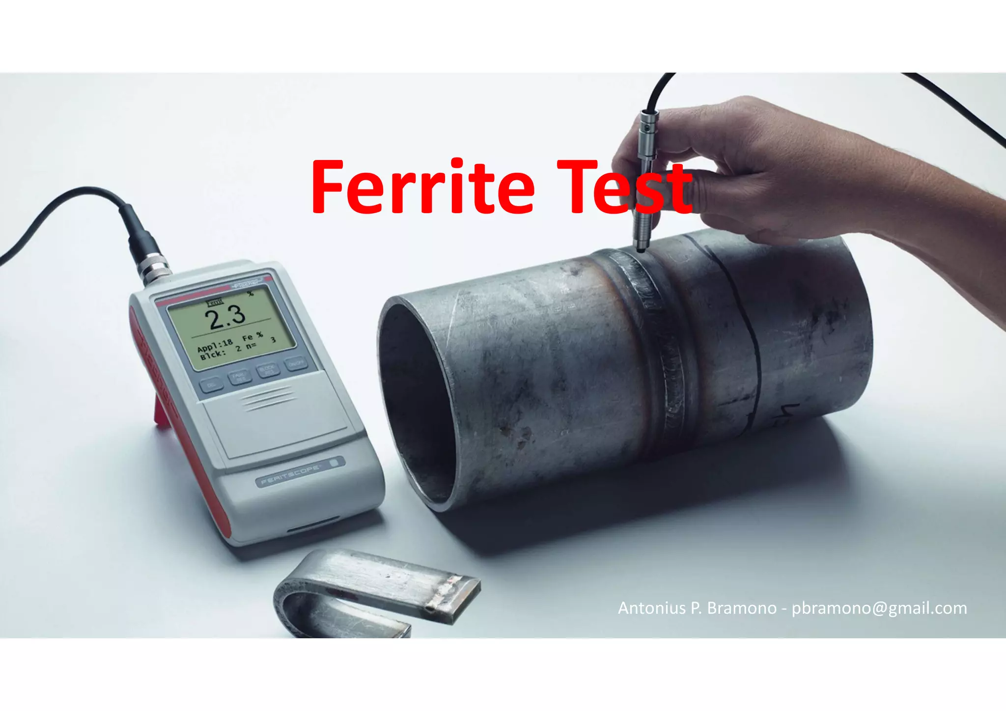


This document discusses various types of weld inspection and testing methods, including: - Destructive tests like bend tests, tensile tests, and notch-toughness tests that involve breaking samples to evaluate weld strength and integrity. - Nondestructive tests like visual inspections, hardness tests, pressure tests, and corrosion tests that examine weld properties without damaging the sample. - Specific tests are used to qualify welders and procedures or inspect production parts by examining factors like weld strength, microstructure, and corrosion resistance. The results of tests are compared to specifications.