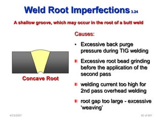
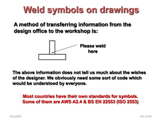
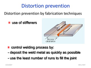
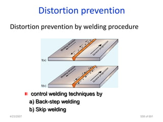
The document discusses key terminology and concepts related to welding inspection. Some key points:
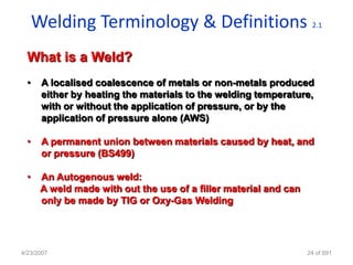
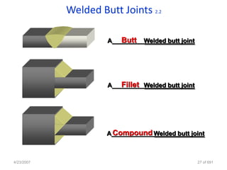
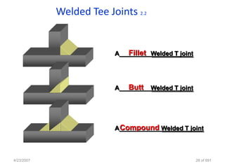
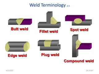
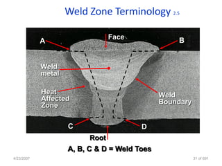
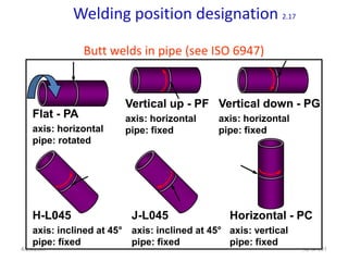
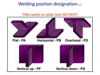
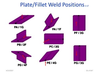
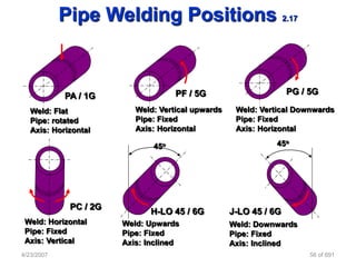
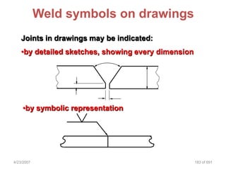
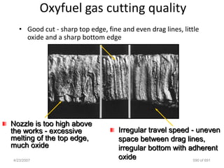
- It defines different types of welds (e.g. butt weld, fillet weld), joints (e.g. butt, tee, lap), and weld zones (e.g. weld metal, heat affected zone).
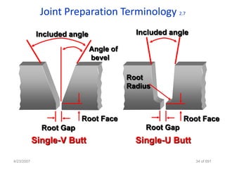
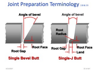
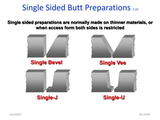
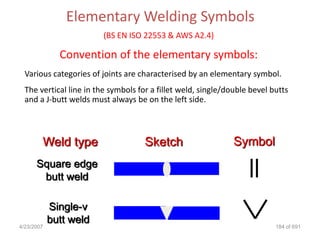
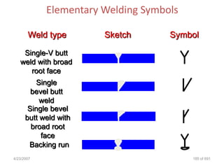
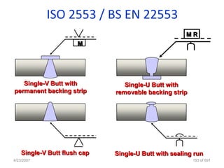
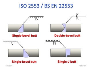
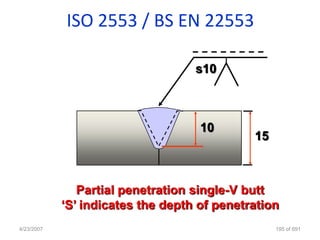
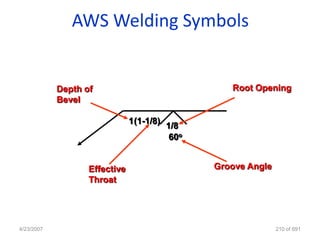
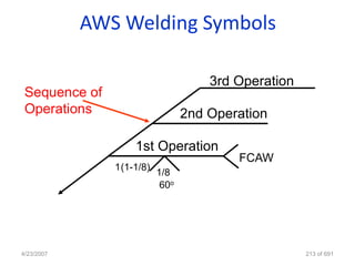
- It discusses joint preparation details like bevel angles, root faces, gaps for different joint types (e.g. single V, single J).
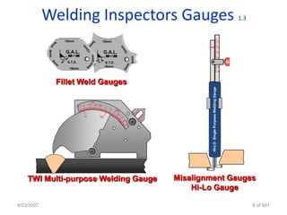
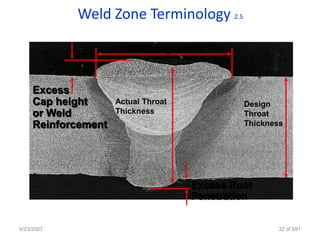
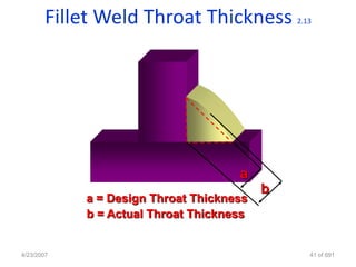
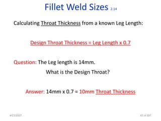
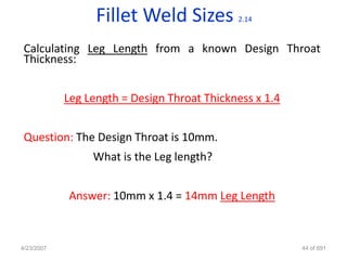
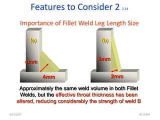
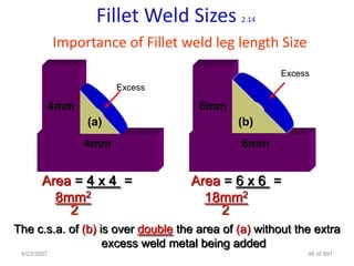
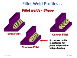
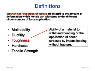
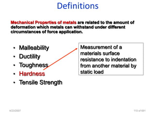
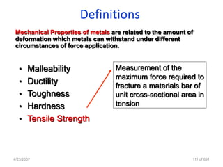
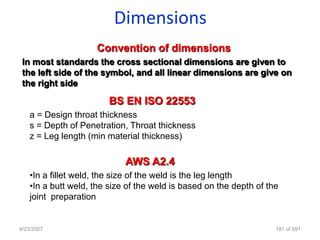
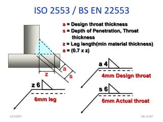
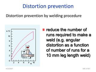
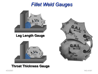
- It covers features of fillet welds like leg length, throat thickness, and how they relate. Leg length and throat thickness determine weld strength.
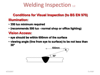
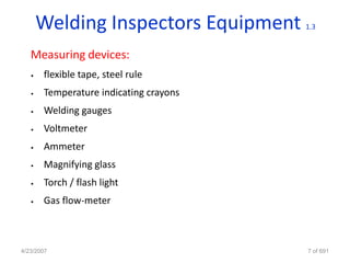
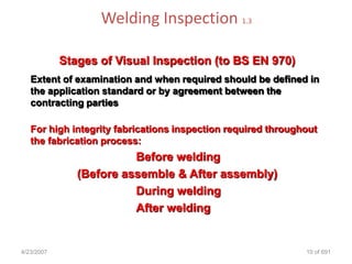
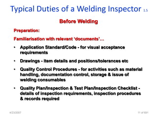
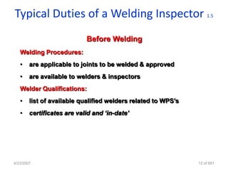
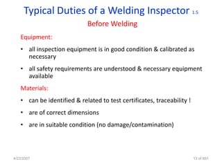
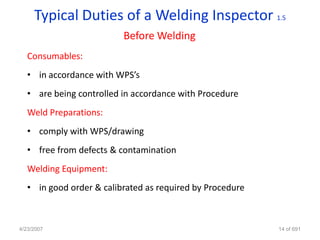
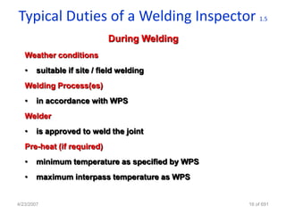
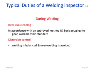
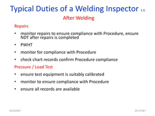
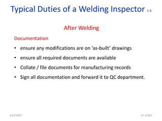
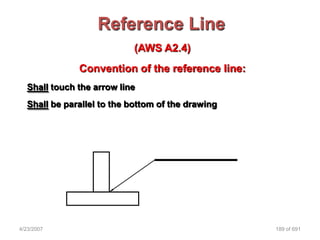
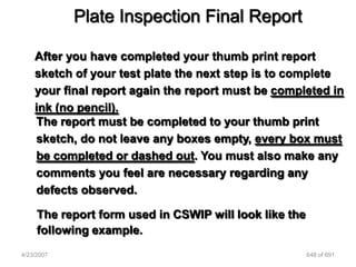
- It also discusses duties of a welding inspector like observing welding, recording