Download as PDF, PPTX

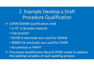
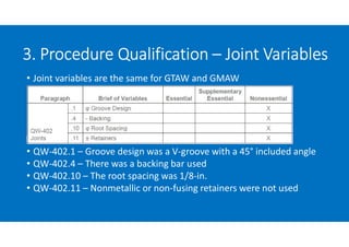
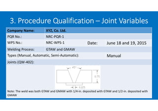
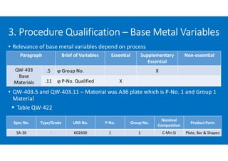
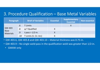
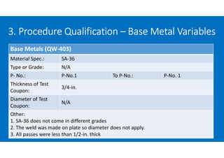
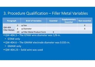
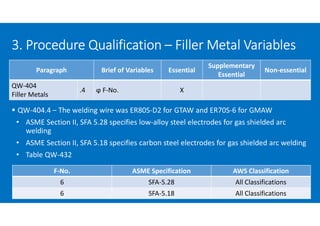
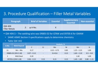
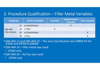
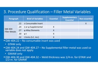
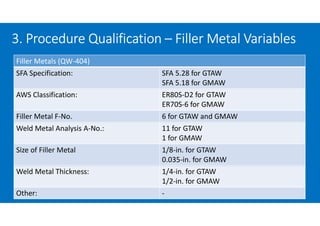
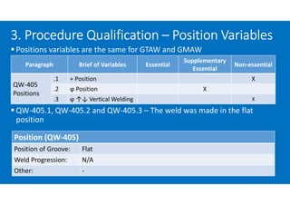
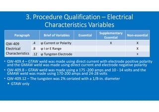
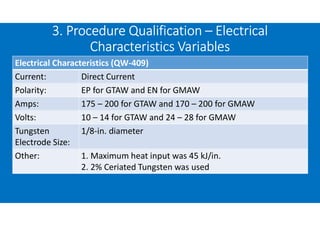
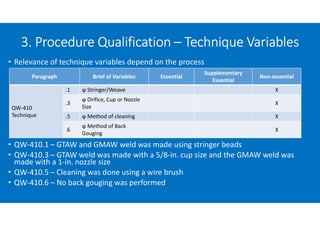
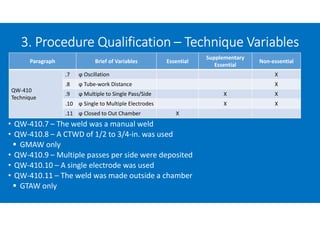
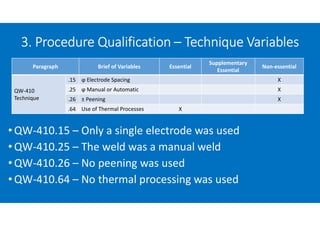
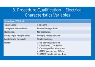
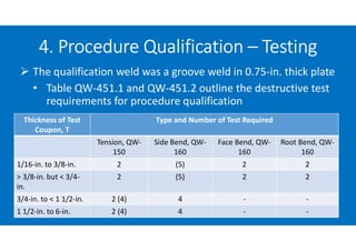
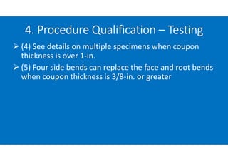
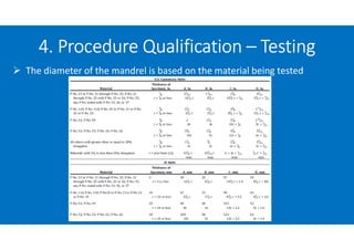
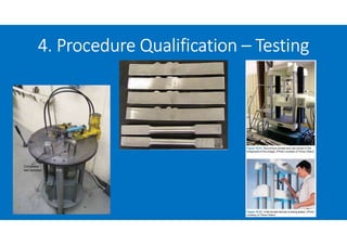
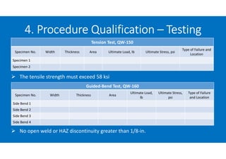
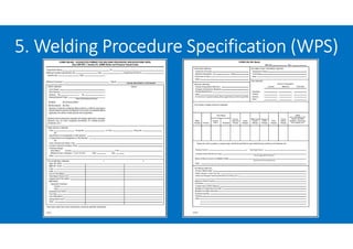


The document outlines the five step process to qualify a welding procedure according to ASME Section IX. It provides details on developing a draft procedure using 0.75" A36 steel plate welded in the flat position using GTAW and GMAW. Variables such as joint design, base metal and thickness, filler metal type and size, welding position, and electrical parameters are documented. The qualification weld was tested to verify it results in an acceptable weld with proper mechanical properties before the welding procedure specification can be used in construction.