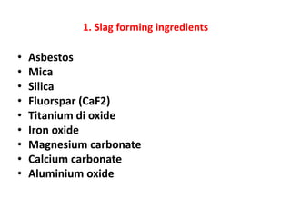
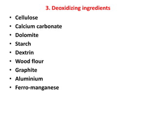
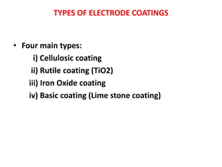
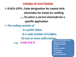
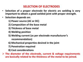
WELDING ELECTRODE
P.GANESAN
ASSISTANT PROFESSOR
DEPARTMENT OF MECHANICAL ENGINEERING
KAMARAJ COLLEGE OF ENGINEERING AND TECHNOLOGY
VIRUDHUNAGAR
1. Specifications of AC transformer / DC generator
2. AC Vs DC welding
3. MIG Vs TIG welding
4. Flux coatings
5. Coding of electrodes
6. Selection of electrodes
SPECIFICATIONS
• AC transformer
• Step down transformer
• Oil cooled
• 3 Ø
• 50 Hz
• 50 to 400 A
• OCV: 50 to 90 V
• Energy consumption: 4
KWh per kg of metal
deposit
• Power Factor = 0.4
• Ƞ = 85 %
• DC generator
• Motor generator
• 3 Ø
• 50 Hz
• 125 to 600 A
• OCV: 30 to 80 V
• Energy consumption: 6 to
10 KWh per kg of metal
deposit
• Power Factor = 0.4
• Ƞ = 60 %
Comparison between AC & DC arc welding
Sl.
No.
Aspect AC welding DC welding
1 Power consumption Low High
2 Arc stability Arc unstable Arc stable
3 Electrode Only coated electrodes Bare electrodes are also used
4 Polarity Work cathode, Electrode
anode.
Vice versa is also possible
Electrode is mostly negative,
Work is positive
5 Suitability Non-ferrous metals cannot
be joined
Suitable for both ferrous &
non-ferrous metals
6 Welding of thin
sections
Not preferred Preferred
7 Operation Noiseless (transformer) Noisy (generator)
8 Efficiency High (85%) Low (60%)
9 Weight Light Heavy
10 Cost Less More
Differences between MIG & TIG welding
Sl.
No.
Aspect MIG TIG
1 Name Metal Inert Gas Welding Tungsten Inert Gas welding
2 Electrode Consumable metallic Non-consumable Tungsten
3 Electrode feed Motor feeds the wire from the
reel
Not required
4 Electrode holder Welding gun or Torch with facility
to continuously feed the wire
Welding torch, with a cap
fitted at the back to cover the
tungsten electrode
5 Welding current DC, reverse polarity Both AC & DC can be used
6 Feed metal Fine wire Filler metal may or may not be
used
7 Base metal
thickness
Upto 40 mm Upto 5 mm
8 Welding speed Fast Slow
Flux coatings
➢ Coating layer thickness: 1 to 3 mm
➢ Weight of the coating: 15 to 30 % of the electrode
INGREDIENTS:
1. Slag forming ingredients
2. Arc stabilising ingredients
3. Deoxidizing ingredients
4. Alloying constituents (to improve strength & quality of weld)
5. Binding materials
1. Slag forming ingredients
• Asbestos
• Mica
• Silica
• Fluorspar (CaF2)
• Titanium di oxide
• Iron oxide
• Magnesium carbonate
• Calcium carbonate
• Aluminium oxide
2. Arc stabilising ingredients
(ionising agents)
• Potassium silicate
• Ti O2 + Zr O2 (Rutile)
• Mica
• Calcium oxide
• Sodium oxide
• Magnesium oxide
• Feldspar (K Al Si3 O8)
Major types of feldspars:
i) Potash feldspar (K2 O. Al2O3. 6SiO2)
ii) Sodium feldspar (Na2O. Al2O3. 6SiO2)
iii) Lime feldspar (CaO. Al2O3. 6SiO2)
3. Deoxidizing ingredients
• Cellulose
• Calcium carbonate
• Dolomite
• Starch
• Dextrin
• Wood flour
• Graphite
• Aluminium
• Ferro-manganese
4. Alloying constituents
(to improve strength & quality of weld)
• TiO2 & Potassium compounds:
To increase the melting rate of the base metal
for better penetration
• Fe powder:
For higher deposition rate
• Va, Ca, Mb, Zr, Cr, Ni, Mn, W
5. Binding materials
• Sodium silicate
• Potassium silicate
• Asbestos
TYPES OF ELECTRODE COATINGS
• Four main types:
i) Cellulosic coating
ii) Rutile coating (TiO2)
iii) Iron Oxide coating
iv) Basic coating (Lime stone coating)
CODING OF ELECTRODES
➢ IS:815-1974…Code designation for coated stick
electrodes for metal arc welding
……To select a correct electrode for a
specific application
➢ The coding consists of
i) a prefix letter,
ii) a code number of 6 digits,
iii) one or more suffix letters.
e.g. E 426 513 H
Method of Manufacture
Type of Covering
Welding Position
Current
Tensile strength
Yield stress
% elongation
Special properties
➢ Prefix letter indicates the method of manufacturing
of electrode
e.g. E…solid extrusion
R…extruded with reinforcement
➢The first digit indicates the type of covering
e.g.
1…high cellulose content
2…high titania content; fairly viscous slag
3…appreciable amount of titania; fluid slag
4…high content of oxides/silicates of Fe, Mn;
produces an inflated slag
5…high content of oxides/silicates of Fe;
heavy solid slag
6…high content of Ca Co3, Ca F2
9…a covering of any other type, not classified
above
➢The second digit indicates the welding position
e.g.
0…F, H, V, D, O
1…F, H, V, O
2…F, H
3…F
4…F, Hf
9…any other welding position not classified
above
F = Flat welding
H = Horizontal
V = Vertical up
D = Vertical down
O = Overhead
Hf = Horizontal fillet
➢The third digit indicates the welding current
conditions recommended by the electrode
manufacturer
e.g.
0…D +
1…D +, A 90
2…D -, A 70
3…D -, A 50
4…D +, A 70
5…D±, A 90
6…D±, A 70
7…D±, A 50
9…any other current conditions not classified above
D + means DC with electrode positive
D – means DC with electrode negative
D ± means electrode positive or negative
A 90 means AC, with an open circuit voltage not less than 90
V
A 70 means AC, with an open circuit voltage not less than 70
V
A 50 means AC, with an open circuit voltage not less than 50
V
➢Fourth & fifth digits indicate mechanical properties
viz. tensile strength & yield stress
e.g.
Range of tensile
strength (N/mm2)
Minimum yield stress
(N/mm2)
41 410 to 510 330
51 510 to 610 360
➢Sixth digit indicates the % elongation in combination
with impact value of deposited metal
e.g.
Strength code Minimum elongation in %
0 41 0 %
1 41 20 %
2 41 22 %
3 41 24 %
4 41 24 %
5 41 24 %
0 51 0 %
1 51 18 %
2 51 18%
3 51 20 %
4 51 20 %
5 51 20 %
➢Suffix letters indicate the special
properties/characteristics
e.g.
H…hydrogen controlled electrode
J…iron powder covering; metal recovery 110 to 130 %
K…iron powder covering; metal recovery 130 to 150 %
L…iron powder covering; metal recovery above 150 %
P…deep penetration
X…radiographic weld quality
SELECTION OF ELECTRODES
• Selection of a proper electrode for electric arc welding is very
important to obtain a good welded joint with proper strength.
• Selection depends on:
1) Power source (AC or DC)
2) Composition of the base metal
3) Thickness of base metal
4) Welding position
5) Welding current (as per electrode manufacturer’s
recommendation)
6) Mechanical properties desired in the joint
7) Penetration required
8) Cost considerations
➢ The diameter of the electrode, current & voltage requirements
are basically related to the thickness of the metal to be joined.
SELECTION OF ELECTRODE

Welding electrode

  • 1.
    WELDING ELECTRODE P.GANESAN ASSISTANT PROFESSOR DEPARTMENTOF MECHANICAL ENGINEERING KAMARAJ COLLEGE OF ENGINEERING AND TECHNOLOGY VIRUDHUNAGAR
  • 2.
    1. Specifications ofAC transformer / DC generator 2. AC Vs DC welding 3. MIG Vs TIG welding 4. Flux coatings 5. Coding of electrodes 6. Selection of electrodes
  • 3.
    SPECIFICATIONS • AC transformer •Step down transformer • Oil cooled • 3 Ø • 50 Hz • 50 to 400 A • OCV: 50 to 90 V • Energy consumption: 4 KWh per kg of metal deposit • Power Factor = 0.4 • Ƞ = 85 % • DC generator • Motor generator • 3 Ø • 50 Hz • 125 to 600 A • OCV: 30 to 80 V • Energy consumption: 6 to 10 KWh per kg of metal deposit • Power Factor = 0.4 • Ƞ = 60 %
  • 4.
    Comparison between AC& DC arc welding Sl. No. Aspect AC welding DC welding 1 Power consumption Low High 2 Arc stability Arc unstable Arc stable 3 Electrode Only coated electrodes Bare electrodes are also used 4 Polarity Work cathode, Electrode anode. Vice versa is also possible Electrode is mostly negative, Work is positive 5 Suitability Non-ferrous metals cannot be joined Suitable for both ferrous & non-ferrous metals 6 Welding of thin sections Not preferred Preferred 7 Operation Noiseless (transformer) Noisy (generator) 8 Efficiency High (85%) Low (60%) 9 Weight Light Heavy 10 Cost Less More
  • 5.
    Differences between MIG& TIG welding Sl. No. Aspect MIG TIG 1 Name Metal Inert Gas Welding Tungsten Inert Gas welding 2 Electrode Consumable metallic Non-consumable Tungsten 3 Electrode feed Motor feeds the wire from the reel Not required 4 Electrode holder Welding gun or Torch with facility to continuously feed the wire Welding torch, with a cap fitted at the back to cover the tungsten electrode 5 Welding current DC, reverse polarity Both AC & DC can be used 6 Feed metal Fine wire Filler metal may or may not be used 7 Base metal thickness Upto 40 mm Upto 5 mm 8 Welding speed Fast Slow
  • 6.
    Flux coatings ➢ Coatinglayer thickness: 1 to 3 mm ➢ Weight of the coating: 15 to 30 % of the electrode INGREDIENTS: 1. Slag forming ingredients 2. Arc stabilising ingredients 3. Deoxidizing ingredients 4. Alloying constituents (to improve strength & quality of weld) 5. Binding materials
  • 7.
    1. Slag formingingredients • Asbestos • Mica • Silica • Fluorspar (CaF2) • Titanium di oxide • Iron oxide • Magnesium carbonate • Calcium carbonate • Aluminium oxide
  • 8.
    2. Arc stabilisingingredients (ionising agents) • Potassium silicate • Ti O2 + Zr O2 (Rutile) • Mica • Calcium oxide • Sodium oxide • Magnesium oxide • Feldspar (K Al Si3 O8) Major types of feldspars: i) Potash feldspar (K2 O. Al2O3. 6SiO2) ii) Sodium feldspar (Na2O. Al2O3. 6SiO2) iii) Lime feldspar (CaO. Al2O3. 6SiO2)
  • 9.
    3. Deoxidizing ingredients •Cellulose • Calcium carbonate • Dolomite • Starch • Dextrin • Wood flour • Graphite • Aluminium • Ferro-manganese
  • 10.
    4. Alloying constituents (toimprove strength & quality of weld) • TiO2 & Potassium compounds: To increase the melting rate of the base metal for better penetration • Fe powder: For higher deposition rate • Va, Ca, Mb, Zr, Cr, Ni, Mn, W
  • 11.
    5. Binding materials •Sodium silicate • Potassium silicate • Asbestos
  • 12.
    TYPES OF ELECTRODECOATINGS • Four main types: i) Cellulosic coating ii) Rutile coating (TiO2) iii) Iron Oxide coating iv) Basic coating (Lime stone coating)
  • 13.
    CODING OF ELECTRODES ➢IS:815-1974…Code designation for coated stick electrodes for metal arc welding ……To select a correct electrode for a specific application ➢ The coding consists of i) a prefix letter, ii) a code number of 6 digits, iii) one or more suffix letters. e.g. E 426 513 H Method of Manufacture Type of Covering Welding Position Current Tensile strength Yield stress % elongation Special properties
  • 14.
    ➢ Prefix letterindicates the method of manufacturing of electrode e.g. E…solid extrusion R…extruded with reinforcement
  • 15.
    ➢The first digitindicates the type of covering e.g. 1…high cellulose content 2…high titania content; fairly viscous slag 3…appreciable amount of titania; fluid slag 4…high content of oxides/silicates of Fe, Mn; produces an inflated slag 5…high content of oxides/silicates of Fe; heavy solid slag 6…high content of Ca Co3, Ca F2 9…a covering of any other type, not classified above
  • 16.
    ➢The second digitindicates the welding position e.g. 0…F, H, V, D, O 1…F, H, V, O 2…F, H 3…F 4…F, Hf 9…any other welding position not classified above F = Flat welding H = Horizontal V = Vertical up D = Vertical down O = Overhead Hf = Horizontal fillet
  • 17.
    ➢The third digitindicates the welding current conditions recommended by the electrode manufacturer e.g. 0…D + 1…D +, A 90 2…D -, A 70 3…D -, A 50 4…D +, A 70 5…D±, A 90 6…D±, A 70 7…D±, A 50 9…any other current conditions not classified above D + means DC with electrode positive D – means DC with electrode negative D ± means electrode positive or negative A 90 means AC, with an open circuit voltage not less than 90 V A 70 means AC, with an open circuit voltage not less than 70 V A 50 means AC, with an open circuit voltage not less than 50 V
  • 18.
    ➢Fourth & fifthdigits indicate mechanical properties viz. tensile strength & yield stress e.g. Range of tensile strength (N/mm2) Minimum yield stress (N/mm2) 41 410 to 510 330 51 510 to 610 360
  • 19.
    ➢Sixth digit indicatesthe % elongation in combination with impact value of deposited metal e.g. Strength code Minimum elongation in % 0 41 0 % 1 41 20 % 2 41 22 % 3 41 24 % 4 41 24 % 5 41 24 % 0 51 0 % 1 51 18 % 2 51 18% 3 51 20 % 4 51 20 % 5 51 20 %
  • 20.
    ➢Suffix letters indicatethe special properties/characteristics e.g. H…hydrogen controlled electrode J…iron powder covering; metal recovery 110 to 130 % K…iron powder covering; metal recovery 130 to 150 % L…iron powder covering; metal recovery above 150 % P…deep penetration X…radiographic weld quality
  • 21.
    SELECTION OF ELECTRODES •Selection of a proper electrode for electric arc welding is very important to obtain a good welded joint with proper strength. • Selection depends on: 1) Power source (AC or DC) 2) Composition of the base metal 3) Thickness of base metal 4) Welding position 5) Welding current (as per electrode manufacturer’s recommendation) 6) Mechanical properties desired in the joint 7) Penetration required 8) Cost considerations ➢ The diameter of the electrode, current & voltage requirements are basically related to the thickness of the metal to be joined.
  • 22.