Downloaded 10,666 times


![Rev 1 January 2009
Practical Visual Inspection
Copyright © TWI Ltd 2009
MEASURE
FROM
THIS
8
Slag inclusion
51
87
22
S DENT
153
Underfill
40
WELD FACE
230
Gas pore
1.5 Ø
Test piece ident:
236
241
30
Arc Strike
Undercut
smooth
1.5 max
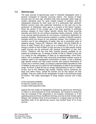
001
C
Date 8 Nov 2001
Joint type: Single V Butt
Length & thickness of plate: 300mm x 10 mm
Welding process: MMA/SMAW
Lack of sidewall fusion
Excess weld metal height : 4mm.
Weld width: 12-14mm
Toe blend: Poor
Linear misalignment: 2mm
Spatter along weld length
A
Welding position: Flat /PA
Code/Specification used: TWI 09-09-02
Signature:
EXAMPLE PLATE REPORT
Name: [Block capitals] STUART DENT
Page 1 of 3
319
DATUM
EDGE](https://image.slidesharecdn.com/138538263-cswip-3-1-new-book-140219061950-phpapp01/85/cswip-3-1-new-book-320-320.jpg)

![321
Page 3 of 3
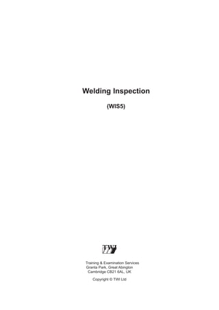
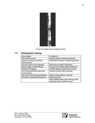
SENTENCE SHEET for PIPE/PLATE INSPECTION REPORT
PRINT FULL NAME S.DENT
SPECIMEN NUMBER 001
Face imperfections
Imperfection types
Excess weld metal
(height)
Toe blend/inter-run blend
Incomplete filling
Slag inclusions
Undercut
Surface porosity
Cracks
Lack of fusion
Arc strikes
Mechanical damage
Misalignment
Imperfections
reported
Maximum value
or total length
1
Code or specification reference
Maximum
Code
allowed by code
section or
2
Table No.3
Sentence
Accept or
reject
4
4mm
2mm
15
Reject
Poor/uneven
40mm
8mm
1.5mm deep
Smooth
None
15mm
10%t Max 1mm
–
–
20mm
None
Seek advice
1.5mm
15
10
7
8
–
–
4
13
11
Reject
Reject
Accept
Reject
Accept
Accept
Reject
Reject?
Refer ?
Reject
1.5mm
1.5mm
20mm
20mm
10%t max 1mm
–
–
Max 1mm ∅
N/A
11
16
6
5
8
–
–
2
NA
Reject
Reject
Reject
Reject
Reject
Accept
Accept
Accept
Accept
None
None
87mm
3
Grinding mark
2mm
ROOT IMPERFECTIONS
Misalignment
Penetration (height)
Lack of root penetration
Lack of root fusion
Root concavity
Root undercut
Cracks
Porosity
Burn through
2mm
4mm
50mm
20mm
10mm L 2mm
None
None
Cluster <1mm
None
This pipe/plate* has been examined to the requirements of [code/specification] TWI 1
and is accepted/rejected* accordingly.
[*Delete whichever is not applicable]
Signature.
S DENT
Comments:
Rev 1 January 2009
Practical Visual Inspection
Copyright © TWI Ltd 2009
Date.00/00/0000.](https://image.slidesharecdn.com/138538263-cswip-3-1-new-book-140219061950-phpapp01/85/cswip-3-1-new-book-322-320.jpg)
![322
Training Sample Only
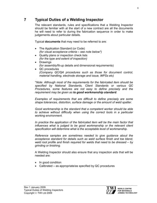
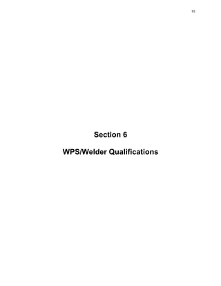
MACRO INSTRUCTION/REPORT SHEET [I.D: AM1030]
CHECK PHOTOGRAPH I.D MATCHES THIS REPORT I.D
All defects to be reported [and sized if required]
Then sentenced to ISO 5817 Level B [StringenT]
Note: Photograph is at X10 Magnification
Chapter 1 Material: Low carbon steel
Chapter 2 Welding process: [MMA/SMAW]
#
1
2
3
4
5
6
7
8
9
10
11
Defect
Excess weld metal
12
Size
Excess penetration
Comments
Signature:
Print full name:
Rev 1 January 2009
Practical Visual Inspection
Copyright © TWI Ltd 2009
Date:
Accept/Reject](https://image.slidesharecdn.com/138538263-cswip-3-1-new-book-140219061950-phpapp01/85/cswip-3-1-new-book-323-320.jpg)


![327
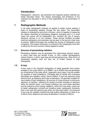
Visual Inspection Plate Report
Name [Block capitals]_______________________Signature ____________________ Test piece identification
Code/Specification used ______________________ Welding process ________________ Joint type__________________
Welding position______________
Length and thickness of plate _______________________ Date
Weld face
M
E
A
S
U
R
E
F
R
O
M
T
H
I
S
D
A
T
U
M
E
D
G
E
A
B
C](https://image.slidesharecdn.com/138538263-cswip-3-1-new-book-140219061950-phpapp01/85/cswip-3-1-new-book-328-320.jpg)

![Sentence Sheet for Pipe/Plate Inspection Report
329
Print Full Name ………………………………………………………………..
Specimen Number …………………….
Face Imperfections
Imperfection Types
Excess weld metal (height)
Imperfections
reported
Maximum Value
or Total Length
1
Code or specification reference
Maximum
Code Section
Allowed by
or
Code
Table No
2
3
Sentence
Accept or
Reject
4
Toe blend / inter-run blend
Incomplete filling
Slag inclusions
Undercut
Surface porosity
Cracks
Lack of fusion
Arc strikes
Mechanical damage
Misalignment
Root Imperfections
Misalignment
Penetration (Height)
Lack of root penetration
Lack of root fusion
Root concavity
Root undercut
Cracks
Porosity
Burnthrough
This pipe/plate* has been examined to the requirements of [code/specification]
..........................…...
and is accepted/rejected* accordingly.
[*Delete whichever is not applicable]
Signature..............….................................…….…
Date...............................
Use this space for any comments](https://image.slidesharecdn.com/138538263-cswip-3-1-new-book-140219061950-phpapp01/85/cswip-3-1-new-book-330-320.jpg)

![Visual Inspection Pipe Report
331
Name [Block capitals]____________ Signature_________________ Pipe Ident#___________
Code/Specification used____________Welding Process________
Joint type____________
Welding position___________ Outside ∅ and Thickness________
Date________________
Weld face
B
A
C
D
1
C
A](https://image.slidesharecdn.com/138538263-cswip-3-1-new-book-140219061950-phpapp01/85/cswip-3-1-new-book-332-320.jpg)

![333
Sentence Sheet for Pipe/Plate Inspection Report
Print Full Name
………………………………………………………………..
Specimen Number …………………….
Face Imperfections
Imperfection Types
Imperfections
Reported
Code or Specification Reference
Maximum
Allowed by
Code
2
Maximum Value
or Total Length
1
Code Section or
Table No
3
Sentence
Accept or
Reject
4
Excess weld metal (height)
Toe blend/inter-run blend
Incomplete filling
Slag inclusions
Undercut
Surface porosity
Cracks
Lack of fusion
Arc strikes
Mechanical damage
Misalignment
Root Imperfections
Misalignment
Penetration (height)
Lack of root penetration
Lack of root fusion
Root concavity
Root undercut
Cracks
Porosity
Burnthrough
This pipe/plate* has been examined to the requirements of [code/specification]..................…...
and is accepted/rejected* accordingly.
[*Delete whichever is not applicable]
Signature..............….................................…….…
Date...............................
Use this space for any comments
3](https://image.slidesharecdn.com/138538263-cswip-3-1-new-book-140219061950-phpapp01/85/cswip-3-1-new-book-334-320.jpg)
![334
Visual Inspection Pipe Report
Name [Block capitals]_STEVE HUGHES___Signature SE Hughes______Pipe Ident__E9___
Welding Process____MMA__Joint type Single V
Code/Specification used YOUR CODE
Welding position_____5G___________Outside Ø and Thickness_mm Date__12 March 03
Weld face
Cap height 6 max
Cap width 17-20
Toe blend poor
Cap height 5 max
Cap width 16-20
Toe blend poor
Hi/Lo 1mm
Stray
flash
A
70
B
3
C
27
10
48
3
5
Poor
25
1
138
Undercut
0.5 sharp
Stray flash
B
Light spatter both
sides
C
Smooth mechanical markings and pitting < 0.5mm deep is evident throughout parent materials over whole pipe
Cap height 4 max
Cap width 17-20
Toe blend poor
Cap height 3.5 max
Cap width 19-24
Toe blend smooth
Poor
restart +
overlap
C
132
Hammer
mark
1 deep
smooth
118
15
14
3
20
16
Arc strike
65
D
A
15
48
72
12
Arc
strike
6
Grinding
0.5 smooth
Grinding
0.5 deep
smooth
pto [for root]
104
10
34
Grinding
0.5 smooth](https://image.slidesharecdn.com/138538263-cswip-3-1-new-book-140219061950-phpapp01/85/cswip-3-1-new-book-335-320.jpg)

![336
Print Full Name
Specimen Number
STEVEN HUGHES
E9
External Defects
Defect Type
Reinforcement (height)
Reinforcement (appearance)
Incomplete filling
Inadequate weld width
Slag Inclusions
Undercut
Surface porosity
Cracks/cracklike defects
Lack of fusion
Arc strikes
Mechanical damage
Laps/Laminations
Misalignment
Longitudinal seams
Pipe/Plate
Section
1
A-A
A-A
A-D
A-A
A-A
A-A
A-A
A-A
A-A
D-C
C-B
A-A
A-A
A-A
Root Defects
Misalignment
Excessive root penetration
Lack of root penetration
Lack of root fusion
Root concavity
Root undercut
Cracks/cracklike defects
Slag inclusions
Porosity
Laps/laminations
A-A
A-A
A-A
A-A
D-A
A-A
A-A
A-B
A-A
A-A
Defects Noted
Accumulative
Total
2
6 max
Non Uniform
None
None
None
0.5 sharp
None
None
None
x4 Total 80mm
1 deep smooth
None
1 max
None
1.5 mm max
4 mm max
None
None
None
1 deep sharp
None
None
None
None
Code or Specification Reference
Maximum
Section/
Accept/Reject
Allowance
Table No
3
4
5
1min 5max
Table 9
REJECT
Smooth
40.2
REJECT
--------------------ACCEPT
--------------------ACCEPT
--------------------ACCEPT
0.5
Table 9
REJECT*
--------------------ACCEPT
---------------------ACCEPT
---------------------ACCEPT
None
15
REJECT **
Not referenced
REJECT ***
---------------------ACCEPT
1.5
26.1
ACCEPT
---------------------ACCEPT
1.5
3
------------------------------------0.5
-------------------------------------------------
Table 7
Table 8
-----------------------------Table 9
-----------------------------------------
ACCEPT****
REJECT
ACCEPT
ACCEPT
ACCEPT
REJECT
ACCEPT
ACCEPT
ACCEPT
ACCEPT
This *pipe/plate has been examined to the requirements of [code/specification]…BS 2633:1987…
.and is accepted/rejected accordingly.
Signature.......SE Hughes..............................
Date...........12 March 2003..........................................
*Delete which is not applicable
Use the other side for any comments
E233-97
* Rejected on sharpness but only 1mm long. Blend smooth and then accept.
** Arc strikes to be ground off and MPI/crack detected.
*** Mechanical damage not referenced but 3mm area exceeds undercut limit-company to confirm rejection.
****No actual limit given for external misalignment so internal limit used – refer to company
Spatter in root to be referred to higher authority for acceptance/rejection.](https://image.slidesharecdn.com/138538263-cswip-3-1-new-book-140219061950-phpapp01/85/cswip-3-1-new-book-337-320.jpg)
![337
Visual Inspection Pipe Report
Name [Block capitals]_STEVE HUGHES_Signature SE Hughes_Pipe Ident__E14__
Code/Specification used YOUR CODE Welding Process_MMAJoint type Single V
Welding position___5G_Outside Ø and Thickness_168 x 12mm Date__12 March 03
Weld Face
Cap height 5max
Cap width 18-21
Toe blend poor
Hi/Lo 1.5
A
Cap height 3mm
Cap width 20-22
Toe blend smooth
Hi/Lo 0.5mm
Stray arc
56
Intermittent Undercut
0.5 deep smooth
A
Stray
103
8
B
Incomplet
e fill
B
50
131
11
C
Poor restart
10
80
28
Mechanical damage
1 deep smooth
10
Poor restart
31
89
98
10
6
Intermittent Undercut
0.5 deep smooth
A
3 x Stray
B
Intermittent Undercut
<1 deep sharp
B
Cap height 3
Cap width 18-21
Toe blend poor
Hi/Lo 1mm
C
Underfill
0
71
65
Intermittent
undercut
0.5 deep
smooth
3
7
80
102
Grinding 1 deep
Undercut
0.5 deep
sharp
50
0
70
C
Undercut
0.5 deep
sharp
93
6
Undercut
0.5 deep
smooth D
124
3
6
10
50
Pipe Ident__E14___
D
D
Spatte
95
25
10
Grinding
1.5 deep
sharp
A
Arc
strike
3x grinding
marks on
weld
65
30
35
Poor
restart
Undercut intermittent
<0.5 deep sharp
2
20
26
10
Grinding 1
deep smooth
PIPE [FOR ROOT]
P.T.O. ROOT FACE
A
Undercut
intermittent
<0.5 deep
smooth
A
118
4
Stray arc
Cap height 5
Cap width 17-20
Toe blend poor
Hi/Lo 1.5mm](https://image.slidesharecdn.com/138538263-cswip-3-1-new-book-140219061950-phpapp01/85/cswip-3-1-new-book-338-320.jpg)
![338
Weld Inspection Report/Sentence Sheet
Sheet 3 of 3
Print Full Name
Specimen Number
STEVEN HUGHES
E 14
External Defects
Defect Type
Reinforcement (height)
Reinforcement
(appearance)
Incomplete filling
Inadequate weld width
Slag Inclusions
Undercut
Surface porosity
Cracks/cracklike
Defects
Lack of fusion
Arc strikes
Mechanical damage
Laps/Laminations
Misalignment
Longitudinal seams
Root Defects
Misalignment
Excessive root
penetration
Lack of root penetration
Lack of root fusion
Root concavity
Root undercut
Cracks/cracklike defects
Slag inclusions
Porosity
Laps/laminations
Pipe/Plate
Section
1
A-A
A-A
Defects Noted
Accumulative
Total
2
5 max
Non Uniform
Code or specification reference
Maximum
Section/
Accept/Reject
Allowance
Table No
3
4
5
1 min 5 max Table 9
ACCEPT
Smooth
40.2
REJECT
A-D
A-A
A-A
A-A
A-A
A-A
130mm
None
None
1mm deep max
None
None
None
----------------------0.5
-----------------------
A-A
D-C
C-B
A-A
A-A
A-A
None
x7 Total 31mm
1.5deep sharp
None
1.5 max
None
---------------------None
15
Not referenced
---------------------1.5
26.1
----------------------
ACCEPT
REJECT*
REJECT **
ACCEPT
ACCEPT***
ACCEPT
Table 9
------------------Table 9
--------------------
REJECT
ACCEPT
ACCEPT
REJECT
ACCEPT
ACCEPT
A-A
A-A
1mm max
3mm max
1.5
3
Table 7
Table 8
ACCEPT
REJECT****
A-A
A-A
D-A
A-A
A-A
A-B
A-A
A-A
None
None
1 deep
1 deep
None
None
None
None
------------------------1.5 max
0.5
-------------------------------------------------
-------------------40.5
Table 9
-----------------------------------------
ACCEPT
ACCEPT
ACCEPT
REJECT
ACCEPT
ACCEPT
ACCEPT
ACCEPT
This *pipe/plate has been examined to the requirements of
[code/specification]…BS2633:1987……
.and is accepted/rejected accordingly.
Signature.......SE Hughes..............................
Date...........12 March 2003..........................................
*Delete which is not applicable
Use the other side for any comments
E233-97
* Arc strikes to be ground off and MPI/crack detected.
** Mechanical damage not referenced but is excessively deep and sharp-refer to company for
rejection.
***No actual limit given for external misalignment so internal limit used – refer to company
**** Rejected on toe blend (see clause 40.6 Profile of root bead)](https://image.slidesharecdn.com/138538263-cswip-3-1-new-book-140219061950-phpapp01/85/cswip-3-1-new-book-339-320.jpg)
![339
Visual Inspection Pipe Report
Name [Block capitals]_STEVE HUGHES Signature SE Hughes__Pipe Ident__E17_
Code/Specification used (YOUR CODE) Welding ProcessMMA__Joint type Single V
Welding position_____2G__Outside Ø and Thickness_219 x 7 mm Date__12 march 03
Weld face
Cap height 3max
Cap width 12-15
Toe blend smooth
Hi/Lo 0.5mm
Stop/start
Smooth
0.5 high
A
5
103
B Undercut
Undercut
1mm sharp
138
5
67
Cap height 3mm
Cap width 12-14
Toe blend sharp
Hi/Lo 0.5mm
Undercut
Undercut
Intermittent
intermittent
2mm sharp
1mm sharp
1mm sharp
15
60
165
5
5
75
Pores (x3)
C
35
25
To
50
100
Arc strikes
Undercut
Intermittent
1mm sharp
0
15
Grinding marks
< 0 5 smooth
Undercut intermittent
<0.5mm smooth
D
Undercut
C
C
Undercut
1mm
1mm
sharp
sharp
0
16
65
5
4
20
10
30
Arc strike
3
Porosity
60
Arc
strike
Arc strike
5
154
Stop/start
Smooth
0.5 high
D
100
4
7
Underfill
3
70
5
Arc strike
Cap height 1-4
Cap width 12-15
Toe blend sharp
Pipe Ident__E17___
Hi/Lo 0.5mm
0
7
Undercut
0.5 sharp
75
5
Undercut
<0.5 sharp
90
5
Undercut
<0.5 sharp
Cap height 3
Cap width 12-15
Toe blend sharp
Hi/Lo
1mm
PTO [FOR ROOT]
P.T.O.for Root
A](https://image.slidesharecdn.com/138538263-cswip-3-1-new-book-140219061950-phpapp01/85/cswip-3-1-new-book-340-320.jpg)

![Print Full Name
Specimen Number
External Defects
Defect Type
Reinforcement (Height)
Reinforcement (Appearance)
Incomplete filling
Inadequate weld width
Slag Inclusions
Undercut
Surface porosity
Cracks/cracklike defects
Lack of fusion
Arc strikes
Mechanical damage
Laps/Laminations
Misalignment
Longitudinal seams
Pipe/Plate
Section
1
A-A
A-A
C-D
A-A
A-A
A-A
A-B/C-D
A-A
A-A
B-D
A-A
A-A
D-A
A-A
Root Defects
Misalignment
Excessive root penetration
Lack of root penetration
Lack of root fusion
Root concavity
Root undercut
Cracks/cracklike defects
Slag inclusions
Porosity
Laps/laminations
341
STEVEN HUGHES
E17
A-A
D-B
D-A
A-A
B-D
B-C/D-A
A-A
A-B
A-A
A-A
Defects Noted
Accumulative
Total
2
4 max
Non uniform
7mm
None
None
2mm deep
max
5mm/3mm
None
None
x4
0.5 smooth
None
1 max
None
Code or Specification Reference
Accept/Reject
Maximum
Section/
o
Allowance
Table N
4
5
3
1.6
7.8.2
REJECT
Uniform
7.8.2
REJECT
None
7.8.2
REJECT
--------------------ACCEPT
--------------------ACCEPT
0.8
9.7.2
REJECT
13mm long 9.3.9.3
------------------------------------------Not referenced
Not referenced
---------------------3
7.2
----------------------
ACCEPT
ACCEPT
ACCEPT
ACCEPT *
ACCEPT **
ACCEPT
ACCEPT
ACCEPT
1mm max
4mm max
1mm
None
0.5 deep
0.5 deep
None
2mm
None
None
3
7.2
Not referenced
25
9.3.1
----------------------1.6 max
9.3.6
0.8
9.7.2
----------------------13
9.3.8.2
---------------------------------------------
ACCEPT
ACCEPT ***
ACCEPT
ACCEPT
ACCEPT ****
ACCEPT
ACCEPT
ACCEPT
ACCEPT
ACCEPT
This *pipe/plate has been examined to the requirements of [code/specification]…API 1104 (19th
edition)....
.and is accepted/rejected accordingly.
Signature.......SE Hughes..............................
Date...........12 March 2003..........................................
*Delete which is not applicable
Use the other side for any comments
E233-97
* Arc strikes not referenced – grind off and MPI/crack detect at company discretion.
** Mechanical damage not referenced but is smooth and not excessively deep-refer to
company.
*** Root penetration not referenced but appears excessive at burnthrough – refer to company.
****Root concavity assessed on radiographic density therefore must not exceed cap height-refer
to graphs.](https://image.slidesharecdn.com/138538263-cswip-3-1-new-book-140219061950-phpapp01/85/cswip-3-1-new-book-342-320.jpg)

This document provides an overview of welding inspection including: - Typical duties of welding inspectors such as visual inspection, reviewing documentation, and checking welding processes - Terms and definitions used in welding inspection - Features that inspectors examine on completed welds such as penetration and types of joints - Conditions required for visual inspection including lighting and access - Stages when inspection is typically required including before, during, and after welding - Records and documentation that inspectors are responsible for collecting and maintaining The document serves as a reference for welding inspectors, outlining their key responsibilities and areas of focus.