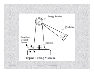
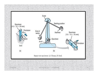
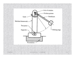
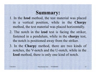
This document discusses various methods for testing materials, including destructive and non-destructive testing. It provides details on hardness testing methods like Rockwell and Brinell, as well as impact testing methods like Izod and Charpy. Specifically, it compares the Izod and Charpy impact testing methods, noting that Izod places the test material vertically and has a single notch type, while Charpy places the material horizontally and uses either a V-notch or U-notch. The document also briefly outlines tensile testing.
This presentation is for mechanical engineering/ civil engineering students to help them understand the different type of destructive mechanical testing of materials. The tensile testing, hardness, impact test procedures are explained in detail.
Unit-II Mechanical Testing
Subject Name: OML751 Testing of Materials
Topics: Various Mechanical Tests [Hardness, Tensile, Impact, Bend, Shear, Creep & Fatigue]
B.E. Mechanical Engineering
Final Year, VII Semester, Open Elective Subject
[As per Anna University R-2017]
Subject Name: Testing of Materials (TOM)
Subject code: OML751
Unit I: Introduction to Materials Testing
B.E. Mechanical Engineering
Final year, VII Semester.
Open Elective Subject
[As per Anna university syllabus; R-2017]
Unit-III Non Destructive Testing (NDT)
Subject Name: OML751 Testing of Materials
Topics: Various NDT tests [Visual inspection, Liquid penetrant test, Magnetic particle test, Thermography test, Radiographic test, Eddy current test, Ultrasonic test, Acoustic emission test]
B.E. Mechanical Engineering
Final Year, VII Semester, Open Elective Subject
[As per Anna University R-2017]
NON DESTRUCTIVE TESTING TECHNIQUES ARE USEFUL FOR FINDING DEFECTS LIKE CRACKS,POROSITY,FLAWS,BLOWHOLES IN MATERIALS WITHOUT DESTRUCTING COMPONENT. IT IS ALSO USEFUL FOR TAKING DECISIONS RELATED TO QUALITY OF MATERIAL OR PRODUCT. Non destructive testing includes study and testing of components by various methods such as dye penetration test, eddy current test, magnetic particle test, ndt, radiography test, ultrasonic test.
This is a ppt which will give u a better understanding of fracture toughness of a material in short time. It also has great exposure to testing method that we do in our laboratory class in undergraduate courses. So good luck with slide.
1. OBJECT
The hardness test is a mechanical test for material properties which are used in engineering
design, analysis of structures, and materials development. The principal purpose of the
hardness test is to determine the suitability of a material for a given application, or the
particular treatment to which the material has been subjected. The ease with which the
hardness test can be made has made it the most common method of inspection for metals and
alloys.
This paper involves an experimental investigation on the flexural behaviour of curved beams and comparison of its results with conventional beams. Curved beams of size 1200 x 150 x 100 mm with varying initial curvature as 4000mm, 2000mm and the concrete strength as M40 is considered. Various reinforcement are provided in the curved beams to predict which reinforcement detail would give more resistant over maximum loading. The material properties of cement, fine aggregate, coarse aggregate and the compressive strength of concrete cube were found out. A total of 12 specimens of curved beams were casted with various combination of reinforcement along with three control specimens. The beams are tested under two point loading both horizontally and vertically. The deflection and maximum moment carrying capacity are investigated to understand its strength. Also analytical modelling is done to determine the ultimate moment carrying capacity using Finite Element Software ABAQUS to compare with the experimental model.
Comparison and Optimization of Wear Rates of Two Types of Dental Composites O...inventionjournals
International Journal of Engineering and Science Invention (IJESI) is an international journal intended for professionals and researchers in all fields of computer science and electronics. IJESI publishes research articles and reviews within the whole field Engineering Science and Technology, new teaching methods, assessment, validation and the impact of new technologies and it will continue to provide information on the latest trends and developments in this ever-expanding subject. The publications of papers are selected through double peer reviewed to ensure originality, relevance, and readability. The articles published in our journal can be accessed online.
"Fracture Toughness I" is the first half of a 2-hour presentation on Fracture Mechanics by metallurgical expert Carl Ziegler of Stork Testing and Metallurgical Consulting , Houston, Texas. In this webinar, Mr. Ziegler will cover many aspects of Fracture Toughness, including theory, applications, specifications, testing methods, and the effects of various stresses, strains and environmental conditions on your materials.
The talent management process is how you organize the management of your human resources. It is how you choose employees, how you hire them, and how (or if) you train them, motivate them, fire them, and so on.
Steps
1.Specify What Skills You Need.
2.Attract the Right People.
3.Onboard and Organize Work.
4.Strategize to Retain Your Best Talent.
5.Plan for Successions.
Principles
Alignment with strategy.
Internal consistency.
Cultural embeddedness.
Management involvement.
Balance of global and local needs.
Employer branding through differentiation
Casting is a manufacturing process in which a liquid material is usually poured into a mold, which contains a hollow cavity of the desired shape, and then allowed to solidify.
Whirling of shafts occurs due to rotational imbalance of a shaft, even in the absence of external loads, which causes resonance to occur at certain speeds, known as critical speeds.
Tenses play a crucial role in the general life of human. It denotes the time an action takes place, whether sometime in the past, in the present or will take some time in the future.
Proper and good education is very important for all of us. It facilitates quality learning all through the life among people of any age group, cast, creed, religion and region. It is the process of achieving knowledge, values, skills, beliefs, and moral habits.
working capital to small scale industrial units. Commercial Banks extend two types of short term assistance to industry namely, granting loans, advances, cash.
Porter Governor is a modification of Watt Governor with central load attached to the sleeve. This load moves up and down the central spindle. The additional force increases the speed of revolution required to enable the balls to rise to any predetermined level.
A governor is a system that is used to maintain the mean speed of an engine, within certain limits, under fluctuating load conditions. It does this by regulating and controlling the amount of fuel supplied to the engine.
Forging is the operation where the metal is heated and then a force is applied to manipulates the metals in such a way that the required final shape is obtained.
phase transition (or phase change) is most commonly used to describe transitions between solid, liquid and gaseous states of matter, and, in rare cases, plasma.
Recrystallization is the process in which deformed grains of the crystal structure are replaced by a new set of stress-free grains that nucleate and grow until all the original grains have been consumed. The process is accomplished by heating the material to temperatures above that of crystallization.
Cosmetic shop management system project report.pdfKamal Acharya
Buying new cosmetic products is difficult. It can even be scary for those who have sensitive skin and are prone to skin trouble. The information needed to alleviate this problem is on the back of each product, but it's thought to interpret those ingredient lists unless you have a background in chemistry.
Instead of buying and hoping for the best, we can use data science to help us predict which products may be good fits for us. It includes various function programs to do the above mentioned tasks.
Data file handling has been effectively used in the program.
The automated cosmetic shop management system should deal with the automation of general workflow and administration process of the shop. The main processes of the system focus on customer's request where the system is able to search the most appropriate products and deliver it to the customers. It should help the employees to quickly identify the list of cosmetic product that have reached the minimum quantity and also keep a track of expired date for each cosmetic product. It should help the employees to find the rack number in which the product is placed.It is also Faster and more efficient way.
Hybrid optimization of pumped hydro system and solar- Engr. Abdul-Azeez.pdffxintegritypublishin
Advancements in technology unveil a myriad of electrical and electronic breakthroughs geared towards efficiently harnessing limited resources to meet human energy demands. The optimization of hybrid solar PV panels and pumped hydro energy supply systems plays a pivotal role in utilizing natural resources effectively. This initiative not only benefits humanity but also fosters environmental sustainability. The study investigated the design optimization of these hybrid systems, focusing on understanding solar radiation patterns, identifying geographical influences on solar radiation, formulating a mathematical model for system optimization, and determining the optimal configuration of PV panels and pumped hydro storage. Through a comparative analysis approach and eight weeks of data collection, the study addressed key research questions related to solar radiation patterns and optimal system design. The findings highlighted regions with heightened solar radiation levels, showcasing substantial potential for power generation and emphasizing the system's efficiency. Optimizing system design significantly boosted power generation, promoted renewable energy utilization, and enhanced energy storage capacity. The study underscored the benefits of optimizing hybrid solar PV panels and pumped hydro energy supply systems for sustainable energy usage. Optimizing the design of solar PV panels and pumped hydro energy supply systems as examined across diverse climatic conditions in a developing country, not only enhances power generation but also improves the integration of renewable energy sources and boosts energy storage capacities, particularly beneficial for less economically prosperous regions. Additionally, the study provides valuable insights for advancing energy research in economically viable areas. Recommendations included conducting site-specific assessments, utilizing advanced modeling tools, implementing regular maintenance protocols, and enhancing communication among system components.
Overview of the fundamental roles in Hydropower generation and the components involved in wider Electrical Engineering.
This paper presents the design and construction of hydroelectric dams from the hydrologist’s survey of the valley before construction, all aspects and involved disciplines, fluid dynamics, structural engineering, generation and mains frequency regulation to the very transmission of power through the network in the United Kingdom.
Author: Robbie Edward Sayers
Collaborators and co editors: Charlie Sims and Connor Healey.
(C) 2024 Robbie E. Sayers
Water scarcity is the lack of fresh water resources to meet the standard water demand. There are two type of water scarcity. One is physical. The other is economic water scarcity.
Industrial Training at Shahjalal Fertilizer Company Limited (SFCL)MdTanvirMahtab2
This presentation is about the working procedure of Shahjalal Fertilizer Company Limited (SFCL). A Govt. owned Company of Bangladesh Chemical Industries Corporation under Ministry of Industries.
Sachpazis:Terzaghi Bearing Capacity Estimation in simple terms with Calculati...Dr.Costas Sachpazis
Terzaghi's soil bearing capacity theory, developed by Karl Terzaghi, is a fundamental principle in geotechnical engineering used to determine the bearing capacity of shallow foundations. This theory provides a method to calculate the ultimate bearing capacity of soil, which is the maximum load per unit area that the soil can support without undergoing shear failure. The Calculation HTML Code included.
2. Why Study Materials Science and
Engineering?
To be able to select a material for a given use based on
considerations of cost and performance.
To understand the limits of materials and the change of their
properties with use.
To be able to create a new material that will have some
desirable properties.
All engineering disciplines need to know about materials.
Even the most "immaterial", like software or system
engineering depend on the development of new materials,
which in turn alter the economics, like software-hardware
trade-offs. Increasing applications of system engineering are
in materials manufacturing (industrial engineering) and
complex environmental systems.
7/28/2018 2Prem Kumar Soni 9755084093
3. classificaTion of MaTerials
Metals: valence electrons are detached from atoms, and spread in an
'electron sea' that "glues" the ions together. Metals are usually strong,
conduct electricity and heat well and are opaque to light (shiny if polished).
Examples: aluminum, steel, brass, gold.
Semiconductors: the bonding is covalent (electrons are shared between
atoms). Their electrical properties depend extremely strongly on minuteatoms). Their electrical properties depend extremely strongly on minute
proportions of contaminants. They are opaque to visible light but
transparent to the infrared. Examples: Si, Ge, GaAs.
Ceramics: atoms behave mostly like either positive or negative ions, and
are bound by Coulomb forces between them. They are usually
combinations of metals or semiconductors with oxygen, nitrogen or carbon
(oxides, nitrides, and carbides). Examples: glass, porcelain, many
minerals.
7/28/2018 3Prem Kumar Soni 9755084093
4. Polymers: are bound by covalent forces and also by weak
van der Waals forces, and usually based on H, C and other
non-metallic elements. They decompose at moderate
temperatures (100 – 400 C), and are lightweight. Other
properties vary greatly. Examples: plastics (nylon, Teflon,
polyester) and rubber.
Other categories are not based on bonding.
A particular microstructure identifies composites, made of
different materials in intimate contact
A particular microstructure identifies composites, made of
different materials in intimate contact
(example: fiberglass, concrete, wood) to achieve specific
properties. Biomaterials can be any type of material that is
biocompatible and used, for instance, to replace human
body parts.
7/28/2018 4Prem Kumar Soni 9755084093
5. Modern Material's Needs
Engine efficiency increases at high temperatures:
requires high temperature structural materials
Use of nuclear energy requires solving problem with
residues, or advances in nuclear waste processing.
Hypersonic flight requires materials that are light,
strong and resist high temperatures.
Hypersonic flight requires materials that are light,
strong and resist high temperatures.
Optical communications require optical fibers that
absorb light negligibly.
Civil construction – materials for unbreakable
windows.
Structures: materials that are strong like metals and
resist corrosion like plastics.
7/28/2018 5Prem Kumar Soni 9755084093
7. Destructive Testing (DT)
• Destructive testing (DT) includes methods
where your material is broken down in order to
determine mechanical properties, such as
strength, toughness and hardness.strength, toughness and hardness.
• In practice it means, for example, finding out if
the quality of a weld is good enough to
withstand extreme pressure or to verify the
properties of a material.
7/28/2018 Prem Kumar Soni 9755084093 7
8. Benefits of Destructive Testing (DT)
It verifies properties of a material
It determines quality of welds
It helps you to reduce failures, accidents and costs
It ensures compliance with regulationsIt ensures compliance with regulations
7/28/2018 Prem Kumar Soni 9755084093 8
9. Types of Destructive testing
Bend test
Break test
Tensile test
Hardness testHardness test
Impact test
7/28/2018 Prem Kumar Soni 9755084093 9
10. 1. Hardness Test
A) Rockwell method
The Rockwell method measures the permanent depth of indentation
produced by a force/load on an indenter. First, a preliminary test force
(commonly referred to as preload or minor load) is applied to a sample
using a diamond or ball indenter. This preload breaks through the surface
to reduce the effects of surface finish. After holding the preliminary test
force for a specified dwell time, the baseline depth of indentation is
measured.measured.
After the preload, an additional load, call the major load, is added to reach
the total required test load. This force is held for a predetermined amount
of time (dwell time) to allow for elastic recovery. This major load is then
released, returning to the preliminary load. After holding the preliminary
test force for a specified dwell time, the final depth of indentation is
measured. The Rockwell hardness value is derived from the difference in
the baseline and final depth measurements. This distance is converted to a
hardness number. The preliminary test force is removed and the indenter is
removed from the test specimen.
7/28/2018 Prem Kumar Soni 9755084093 10
11. • Preliminary test loads (preloads) range from 3 kgf (used in the
“Superficial” Rockwell scale) to 10 kgf (used in the “Regular” Rockwell
scale). Total test forces range from 15kgf to 150 kgf (superficial and
regular) to 500 to 3000 kgf (macrohardness).
• Test Method Illustration
A = Depth reached by indenter after application of
preload (minor load)
B = Position of indenter during Total load, Minor plusB = Position of indenter during Total load, Minor plus
Major loads
C = Final position reached by indenter after elastic
recovery of sample material
D = Distance measurement taken representing
difference between preload and major load position.
This distance is used to calculate the Rockwell
Hardness Number.
7/28/2018 Prem Kumar Soni 9755084093 11
13. • A variety of indenters may be used: conical diamond with a
round tip for harder metals to ball indenters ranges with a
diameter ranging from 1/16” to ½” for softer materials.
When selecting a Rockwell scale, a general guide is to
select the scale that specifies the largest load and the largest
indenter possible without exceeding defined operation
conditions and accounting for conditions that may influence
the test result. These conditions include test specimens thatthe test result. These conditions include test specimens that
are below the minimum thickness for the depth of
indentation; a test impression that falls too close to the edge
of the specimen or another impression; or testing on
cylindrical specimens.
7/28/2018 Prem Kumar Soni 9755084093 13
14. b) Brinell hardness test method
The Brinell hardness test method as used to determine Brinell
hardness, is defined in ASTM E10. Most commonly it is used to test
materials that have a structure that is too coarse or that have a
surface that is too rough to be tested using another test method, e.g.,
castings and forgings.
Brinell testing often use a very high test load (3000 kgf) and a
10mm diameter indenter so that the resulting indentation averages
out most surface and sub-surface inconsistencies.
The Brinell method applies a predetermined test load (F) to a
carbide ball of fixed diameter (D) which is held for a predetermined
The Brinell method applies a predetermined test load (F) to a
carbide ball of fixed diameter (D) which is held for a predetermined
time period and then removed. The resulting impression is
measured with a specially designed Brinell microscope or optical
system across at least two diameters – usually at right angles to each
other and these results are averaged (d). Although the calculation
below can be used to generate the Brinell number, most often a chart
is then used to convert the averaged diameter measurement to a
Brinell hardness number.
7/28/2018 Prem Kumar Soni 9755084093 14
15. Common test forces
range from 500kgf
often used for non-
ferrous materials to
3000kgf usually used
for steels and cast iron.
There are other Brinell
scales with load as low
as 1kgf and 1mm
diameter indenters but
7/28/2018 Prem Kumar Soni 9755084093 15
D = Ball diameter
d = impression diameter
F = load
HB = Brinell result
diameter indenters but
these are infrequently
used.
16. Typically the greatest source of error in Brinell testing is the
measurement of the indentation. Due to disparities in
operators making the measurements, the results will vary
even under perfect conditions. Less than perfect conditions
can cause the variation to increase greatly. Frequently the
test surface is prepared with a grinder to remove surface
conditions.
The jagged edge makes interpretation of the indentation The jagged edge makes interpretation of the indentation
difficult. Furthermore, when operators know the
specifications limits for rejects, they may often be
influenced to see the measurements in a way that increases
the percentage of “good” tests and less re-testing.
7/28/2018 Prem Kumar Soni 9755084093 16
17. c). Vickers hardness test method
The Vickers hardness test method, also referred to as a
micro hardness test method, is mostly used for small parts,
thin sections, or case depth work.
The Vickers method is based on an optical measurement
system. The Microhardness test procedure, ASTM E-384,
specifies a range of light loads using a diamond
indenter to make an indentation which is measured andindenter to make an indentation which is measured and
converted to a hardness value. It is very useful for testing
on a wide type of materials, but test samples must be highly
polished to enable measuring the size of the impressions. A
square base pyramid shaped diamond is used for testing in
the Vickers scale. Typically loads are very light, ranging
from 10gm to 1kgf, although "Macro" Vickers loads can
range up to 30 kg or more.
7/28/2018 Prem Kumar Soni 9755084093 17
18. The Microhardness methods are used to test on metals, ceramics,
composites - almost any type of material.
Since the test indentation is very small in a Vickers test, it is useful
for a variety of applications: testing very thin materials like foils or
measuring the surface of a part, small parts or small areas,
measuring individual microstructures, or measuring the depth of
case hardening by sectioning a part and making a series of
indentations to describe a profile of the change in hardness.
Sectioning is usually necessary with a microhardness test in order to
provide a small enough specimen that can fit into the tester.provide a small enough specimen that can fit into the tester.
Additionally, the sample preparation will need to make the
specimen’s surface smooth to permit a regular indentation shape and
good measurement, and to ensure the sample can be held
perpendicular to the indenter.
Often the prepared samples are mounted in a plastic medium to
facilitate the preparation and testing. The indentations should be as
large as possible to maximize the measurement resolution. (Error is
magnified as indentation sizes decrease) The test procedure is
subject to problems of operator influence on the test results.
7/28/2018 Prem Kumar Soni 9755084093 18
20. 2. Impact Test
The purpose of impact testing is to measure an object's
ability to resist high-rate loading. It is usually thought
of in terms of two objects striking each other at high
relative speeds. A part, or material's ability to resist
impact often is one of the determining factors in the
service life of a part, or in the suitability of a designatedservice life of a part, or in the suitability of a designated
material for a particular application. Impact resistance
can be one of the most difficult properties to quantify.
The ability to quantify this property is a great
advantage in product liability and safety.
Impact Testing most commonly consists
of Charpy and IZOD Specimen configurations.
7/28/2018 Prem Kumar Soni 9755084093 20
21. The Izod test
The Izod test involved the striker, the testing material, and the
pendulum. The striker was fixed at the end of the pendulum.
The test material was fastened at a vertical position at the
bottom, and the notch was facing the striker. The striker
swings downward, hitting the test material in the middle, at the
bottom of it’s swing, and is left free at the top.
The notch is placed to concentrate the stress, and provoke
delicate failure. It lowers distortion and decreases the ductiledelicate failure. It lowers distortion and decreases the ductile
fracture. The test was done easily and quickly to examine the
quality of the materials, and test whether it meets the specific
force of collision properties. It is also used to evaluate the
materials for overall hardiness. It is not applicable to
compound materials because of the influence of complicated
and inconsistent failure modes.
7/28/2018 Prem Kumar Soni 9755084093 21
22. • The notch is very important because it can affect the
result of the test. The making of the notch has been a
problem. Initially, the radius of the notch is crucial. The
radius should not change. It has an essential effect on
the competence of the sample to absorb the collision.
• The blades in the notch can overheat the polymers, and• The blades in the notch can overheat the polymers, and
deteriorate the materials surrounding the notch, which
could lead to an inaccurate test result. The Izod method
chose a short projection, supported at one end, to
produce better steel tools for cutting metal
7/28/2018 Prem Kumar Soni 9755084093 22
23. The Charpy method
The Charpy method includes striking an appropriate test material
with a striker fastened at the end of a pendulum. The test material is
secured horizontally in place at both ends, and the striker hits the
center of the test material, behind a machined notch. The notch is
positioned away from the striker, fastened in a pendulum. The test
material usually measures 55x10x10 millimeters.
The Charpy method has a machined notch across one of the larger
faces. There are two types of charpy notch, a V-notch or a U-notch.faces. There are two types of charpy notch, a V-notch or a U-notch.
The V-notch, or the AV-shaped notch, measures 2 millimeters deep,
with a 45 degree angle and 0.25 millimeter radius, parallel to the
base. The U-notch, or keyhole notch, is 5 millimeters deep notch,
with a 1 millimeter radius at the bottom of the notch. Higher speeds
and collision energy could be achieved in a vertical style fall. This
method proved to be reliable, and gave qualitative collision data.
7/28/2018 Prem Kumar Soni 9755084093 23
27. Summary:
1. In the Izod method, the test material was placed
in a vertical position, while in the Charpy
method, the test material was placed horizontally.
2. The notch in the izod test is facing the striker,
fastened in a pendulum, while in the charpy test,fastened in a pendulum, while in the charpy test,
the notch is positioned away from the striker.
3. In the Charpy method, there are two kinds of
notches, the V-notch and the U-notch, while in the
Izod method, there is only one kind of notch.
7/28/2018 Prem Kumar Soni 9755084093 27
28. 3. Tensile testing
Tensile testing is a way of determining how
something will react when it is pulled apart -
when a force is applied to it in tension.
Tensile testing is one of the simplest and most
widely used mechanical tests. By measuring thewidely used mechanical tests. By measuring the
force required to elongate a specimen to breaking
point, material properties can be determined that
will allow designers and quality managers to
predict how materials and products will behave in
their intended applications.
7/28/2018 Prem Kumar Soni 9755084093 28
29. Benefit of tensile test
The data produced in a tensile test can be used in
many ways including:
To determine batch quality
To determine consistency in manufactureTo determine consistency in manufacture
To aid in the design process
To reduce material costs and achieve lean
manufacturing goals
To ensure compliance with international and
industry standards
7/28/2018 Prem Kumar Soni 9755084093 29
34. Procedure
• A material is gripped at both ends by an
apparatus, which slowly pulls lengthwise on
the piece until it fractures. The pulling force is
called a load, which is plotted against thecalled a load, which is plotted against the
material length change, or displacement. The
load is converted to a stress value and the
displacement is converted to a strain value.
7/28/2018 Prem Kumar Soni 9755084093 34
35. • First, the point on the graph labeled number 1
indicates the end of the elastic region of the curve. Up
to this point, the material stretches in an elastic or
reversible manner.
• All materials are made up of a collection of atoms.
Elasticity can be best understood by imaging the atoms
are connected by springs. As we pull on the material,
the springs between the atoms get longer and thethe springs between the atoms get longer and the
material lengthens. The elastic portion of the curve is a
straight line. A straight line indicates that the material
will go back to its original shape when the load is
removed.
7/28/2018 Prem Kumar Soni 9755084093 35
36. • At this point the curve has begun to bend over, or is no longer
linear. This point is known as the 0.2% offset yield strength. It
indicates the strength of the material just as it starts to
permanently change shape. It is determined as the value of the
stress at which a line of the same slope as the initial portion (elastic
region) of the curve that is offset by a strain of 0.2% or a value of
0.002 strain intersects the curve.
• In our example, the 0.2% offset yield strength is a 88 ksi.
• This is a very important aspect of strength. It basically tells us the
amount of stress we can apply before the material starts to
This is a very important aspect of strength. It basically tells us the
amount of stress we can apply before the material starts to
permanently change shape, putting it on a path to eventual failure.
Those who design parts that are used under stress must see that
the stress or force on the part never exceeds this value.
7/28/2018 Prem Kumar Soni 9755084093 36
37. • As we move up from point 2 the load or "stress" on the
material increases until we reach a maximum applied stress,
while the material deforms or changes shape uniformly
along the entire gauge length. When we reach point 3, we
can determine the tensile strength or maximum stress (or
load) the material can support. It is not a very useful
property, since the material has permanently deformed at
this point. After we reach this point, the stress begins tothis point. After we reach this point, the stress begins to
curve drastically downward. This corresponds to localized
deformation, which is observed by a noticeable “necking”
or reduction in the diameter and corresponding cross-
section of the sample within a very small region. If we
release the load in this area, the material will spring back a
little but will still suffer a permanent shape change.
7/28/2018 Prem Kumar Soni 9755084093 37
38. • Finally, as we follow the curve we eventually reach a point
where the material breaks or fails. Of interest here is the
final degree to which the material changes shape. This is the
“ductility” of the material. It is determined by the
intersection of line number 4, having the same slope as the
linear portion of the curve, with the strain axis.
• Our example shows a strain of 0.15. The 15% change in
length is the amount of “ductility”.length is the amount of “ductility”.
• When the sample fractures or breaks the load is released.
Therefore, the atoms elastically stretched will return to their
non-loaded positions. Other information about the
mechanical response of a material can also be gathered from
a fracture test.
7/28/2018 Prem Kumar Soni 9755084093 38
39. • For further understanding the topic you can go
to following link
• http://me.aut.ac.ir/staff/solidmechanics/alizade
h/Tensile%20Testing.htmh/Tensile%20Testing.htm
7/28/2018 Prem Kumar Soni 9755084093 39
40. 4. Compression Test
• Compression testing is a very common testing method that
is used to establish the compressive force or crush
resistance of a material and the ability of the material to
recover after a specified compressive force is applied and
even held over a defined period of time. Compression tests
are used to determine the material behaviour under a load.
The maximum stress a material can sustain over a period
are used to determine the material behaviour under a load.
The maximum stress a material can sustain over a period
under a load (constant or progressive) is determined.
Compression testing is often done to a break (rupture) or to
a limit. When the test is performed to a break, break
detection can be defined depending on the type of material
being tested. When the test is performed to a limit, either a
load limit or deflection limit is used.
7/28/2018 Prem Kumar Soni 9755084093 40
41. Common compression testing results are:
- Load at Rupture
- Deflection at Rupture
- Work at Rupture
- Maximum Load
- Deflection at Maximum Load
- Work at Maximum Load- Work at Maximum Load
- Stiffness
- Chord Slope
- Offset Yield
- Stress
- Strain
7/28/2018 Prem Kumar Soni 9755084093 41
44. 5. Shear testing
• Shear testing is performed to determine the
shear strength of a material. It measures the
maximum shear stress that may be sustained
before a material will rupture. Shear is
typically reported as MPa (psi) based on thetypically reported as MPa (psi) based on the
area of the sheared edge.
• Shear testing is commonly used with adhesives
and can be used in either a tensile or
comprehensive method
7/28/2018 Prem Kumar Soni 9755084093 44
46. Theory and procedure
• Shear testing is different from tensile and
compression testing in that the forces applied
are parallel to the upper and lower faces of the
object under test. Materials behave differentlyobject under test. Materials behave differently
in shear than in tension or compression,
resulting in different values for strength and
stiffness. Shear testing applies a lateral shear
force to the specimen until failure results.
7/28/2018 Prem Kumar Soni 9755084093 46
47. Fasteners, such as bolts, may be pulled in single or double
shear to SAE or ASTM specification. A single shear test
fixture uses two blades with centrally located transverse
holes. One blade is kept stationary with the fastener in place
while the second blade is moved in a parallel plane, which
shears the fastener. Double shear testing uses a second
stationary blade support behind the shearing blade.
Lap shear testing is performed to determine the shear
strength of an adhesive that is applied to two metal plates
and pulled to failure. It can be used to compare between
strength of an adhesive that is applied to two metal plates
and pulled to failure. It can be used to compare between
adhesive types or different lots within the same adhesive.
Specimens are cut and prep per ASTM standard prior to
testing.
7/28/2018 Prem Kumar Soni 9755084093 47
48. 6. Bending Test
• Purpose of Bend Testing: ... These
characteristics can be used to determine
whether a material will fail under pressure and
are especially important in any constructionare especially important in any construction
process involving ductile materials loaded
with bending forces.
7/28/2018 Prem Kumar Soni 9755084093 48
49. Procedure
• The bend test is a simple and inexpensive qualitative test that can be
used to evaluate both the ductility and soundness of a material. It is
often used as a quality control test for butt-welded joints, having the
advantage of simplicity of both test piece and equipment.
• No expensive test equipment is needed, test specimens are easily
prepared and the test can, if required, be carried out on the shop
floor as a quality control test to ensure consistency in production.floor as a quality control test to ensure consistency in production.
• The bend test uses a coupon that is bent in three point bending to a
specified angle.
• The outside of the bend is extensively plastically deformed so that
any defects in, or embrittlement of, the material will be revealed by
the premature failure of the coupon.
• The bend test may be free formed or guided.
7/28/2018 Prem Kumar Soni 9755084093 49
50. • The guided bend test is where the coupon is
wrapped around a former of a specified diameter
and is the type of test specified in the welding
procedure and welder qualification specifications.
For example, it may be a requirement in ASME
IX, ISO 9606 and ISO 15614 Part 1.
• As the guided bend test is the only form of bend• As the guided bend test is the only form of bend
test specified in welding qualification
specifications it is the only one that will be dealt
with in this article.
• Typical bend test jigs are illustrated
in Fig.1(a) and 1(b).
7/28/2018 Prem Kumar Soni 9755084093 50
52. The strain applied to the specimen depends on the
diameter of the former around which the coupon is bent
and this is related to the thickness of the coupon 't',
normally expressed as a multiple of 't' eg 3t, 4t etc.
The former diameter is specified in the test standard
and varies with the strength and ductility of the material
- the bend former diameter for a low ductility material
such as a fully hard aluminium alloy may be as large assuch as a fully hard aluminium alloy may be as large as
8t. An annealed low carbon steel on the other hand may
require a former diameter of only 3t. The angle of bend
may be 90°, 120° or 180° depending on the
specification requirements.
7/28/2018 Prem Kumar Soni 9755084093 52