Downloaded 698 times
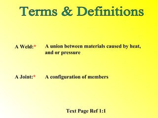
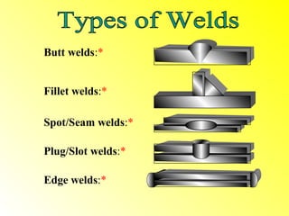
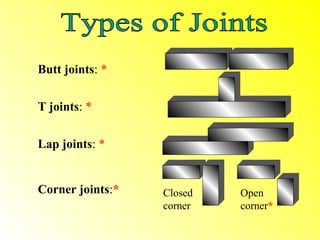
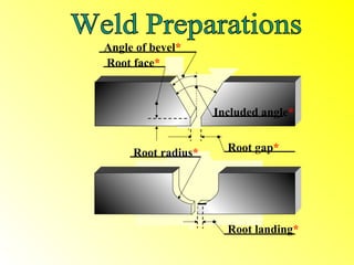
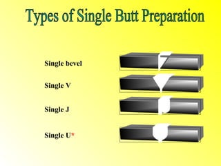
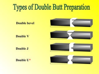
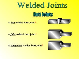

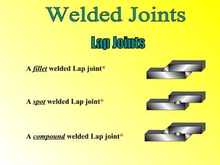
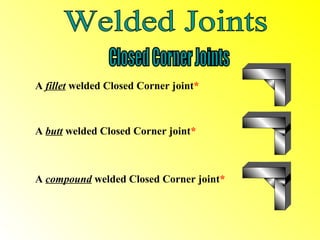
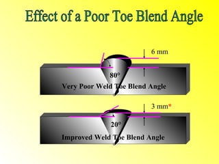
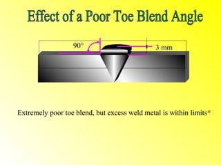
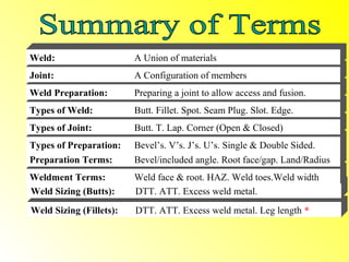

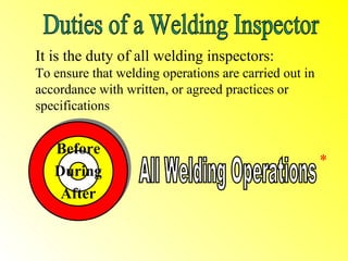
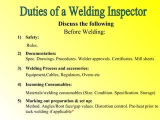

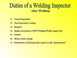
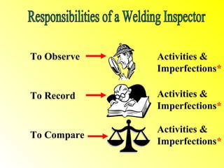
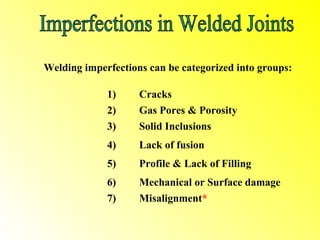
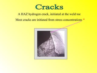
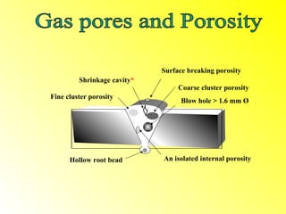
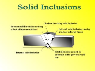
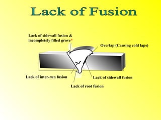
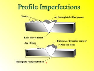
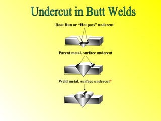
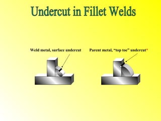
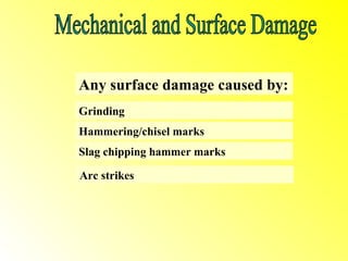
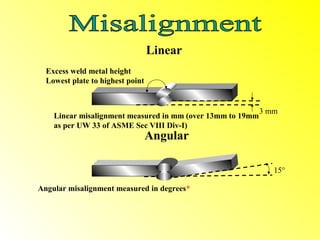
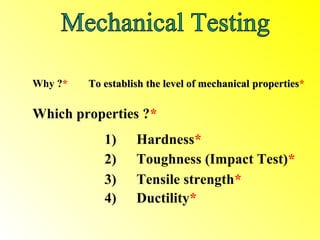
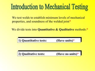
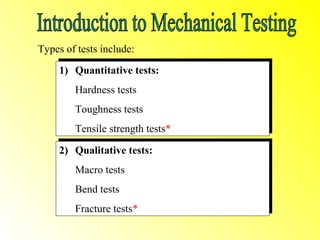
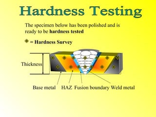
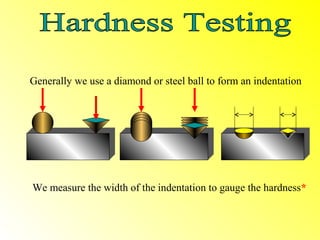
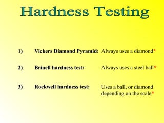

This document provides an introduction to CSWIP 3.1 welding inspection standards. It defines key welding terms like joints, welds, and weld preparations. It describes the responsibilities of welding inspectors to ensure safety and quality before, during, and after welding operations. The document also summarizes different types of welding imperfections and mechanical tests used by inspectors, including hardness testing, tensile testing, and bend testing specimens under a macroscope.