Downloaded 1,164 times

![30
Sievert’s law
• k is the equilibrium constant,
• [gas] is the concentration as weight percent (wt%) of a
particular gas in the molten metal, and
• Pgas2 is the partial pressure of the particular gas in
diatomic molecular form.
• This relationship, known as Sievert’s law, applies to all
diatomic gases, including N2, O2 and H2](https://image.slidesharecdn.com/weldinglectures14-16-150902090349-lva1-app6891/75/Welding-lectures-14-16-30-2048.jpg)

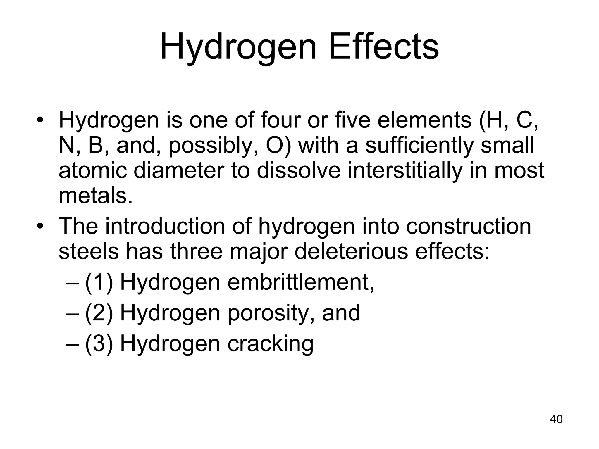
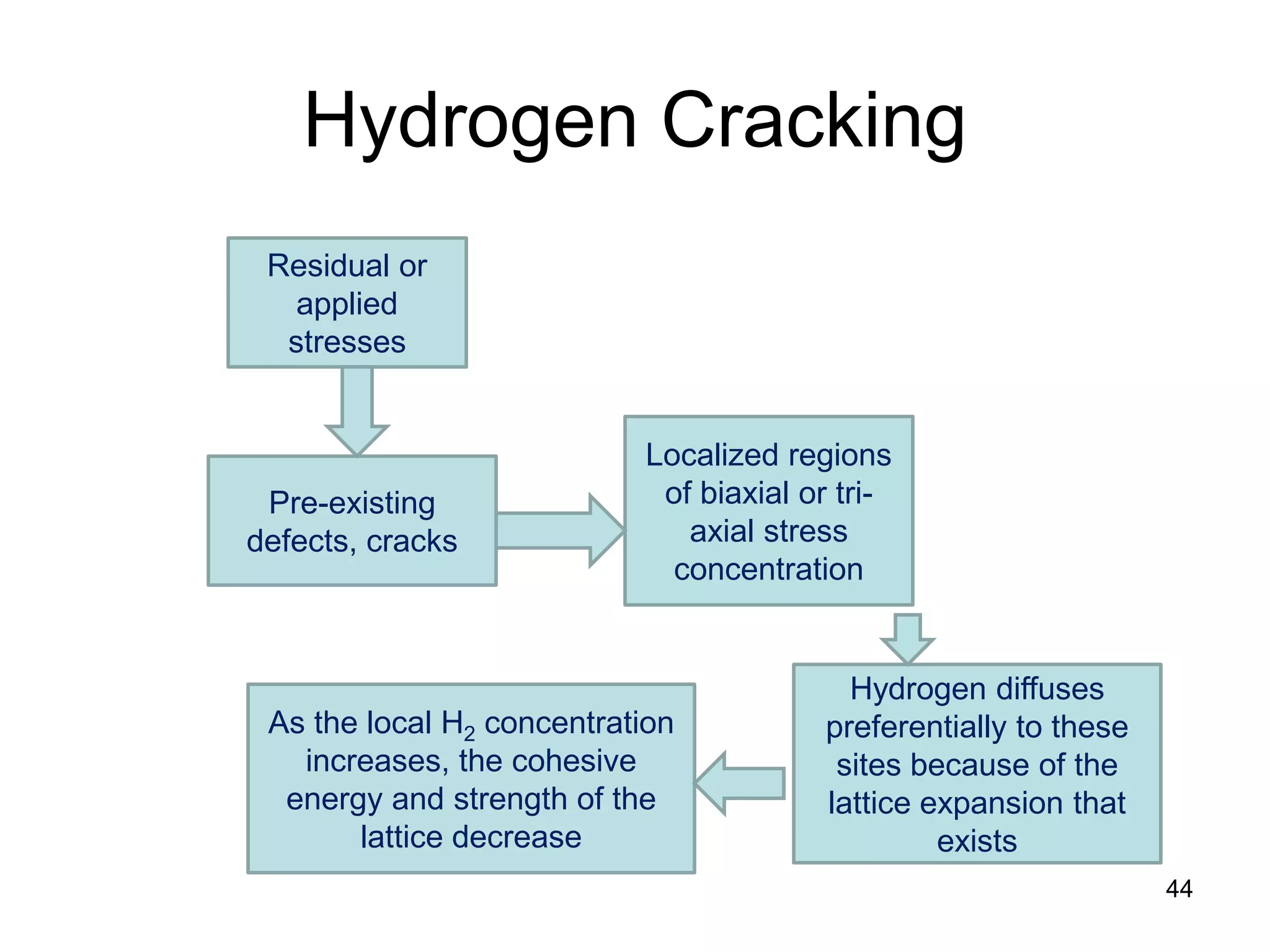
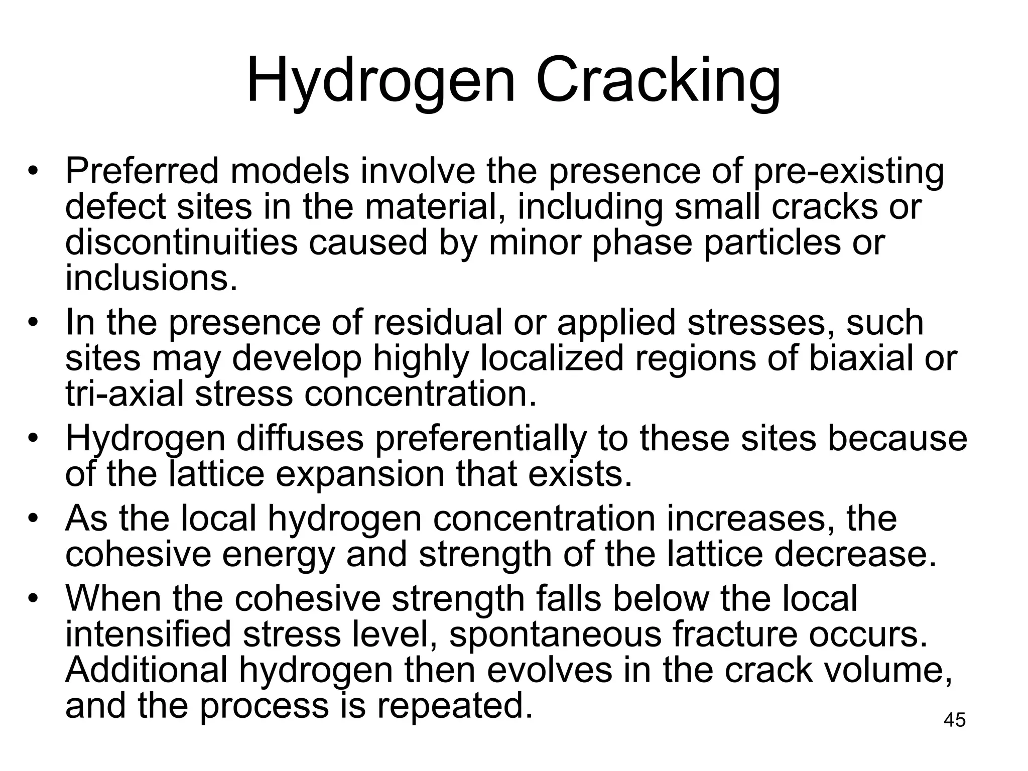
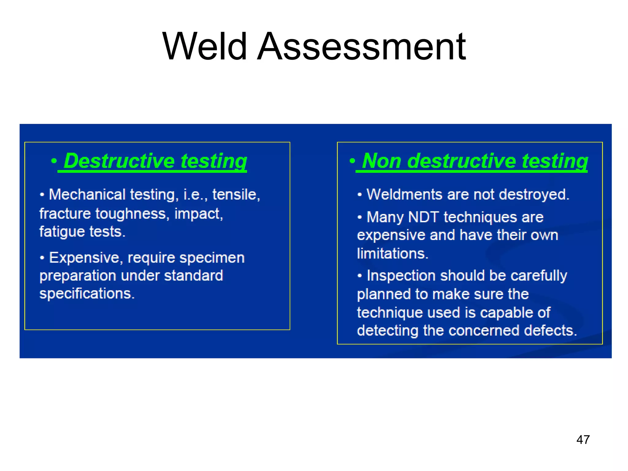
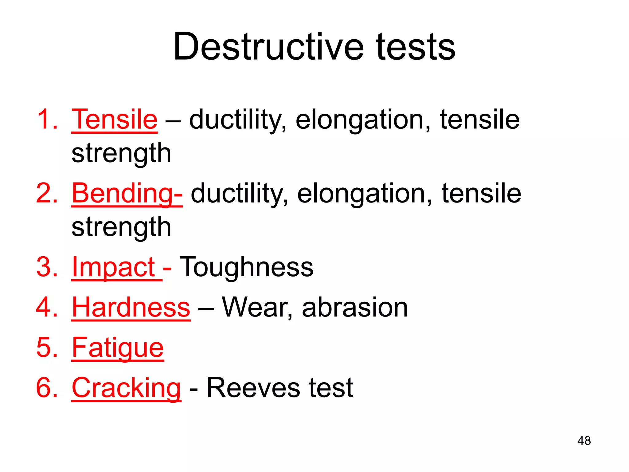
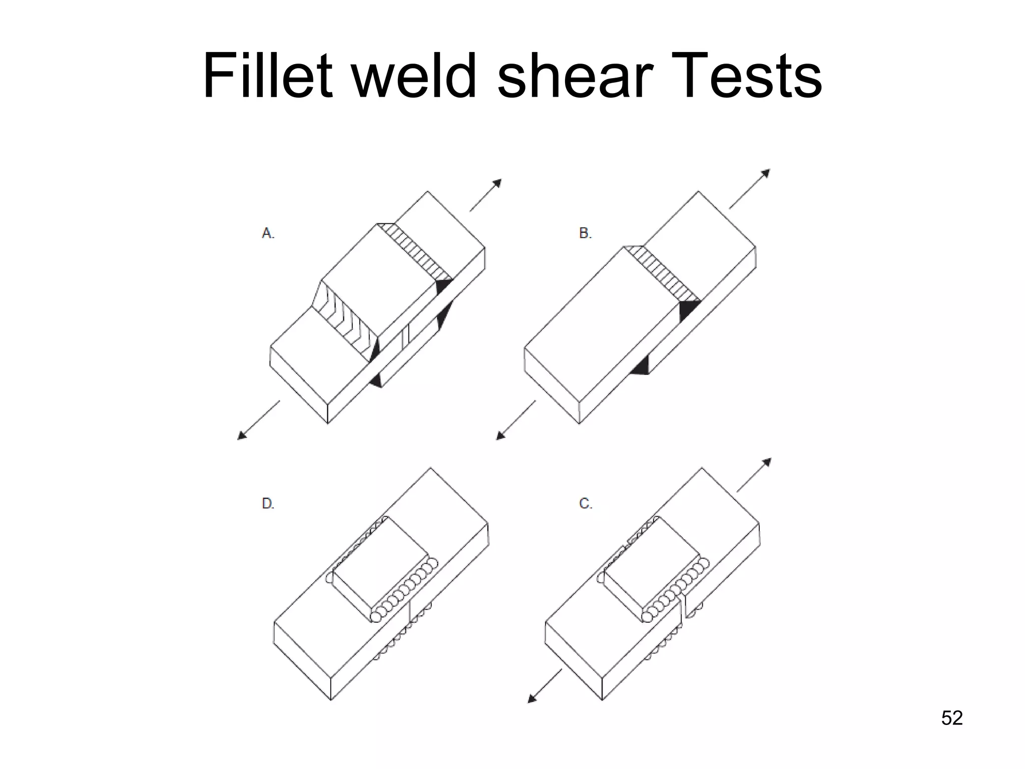
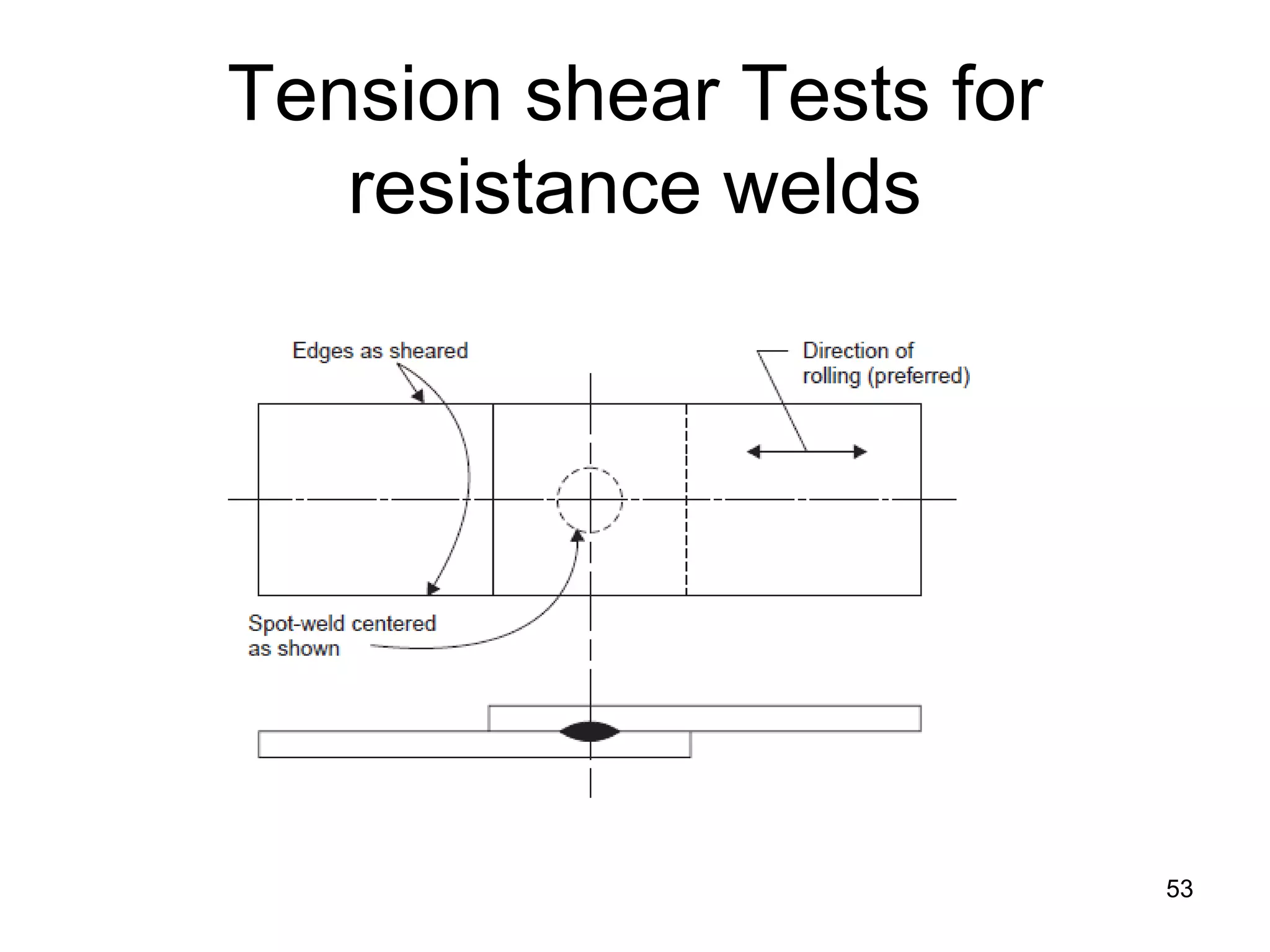
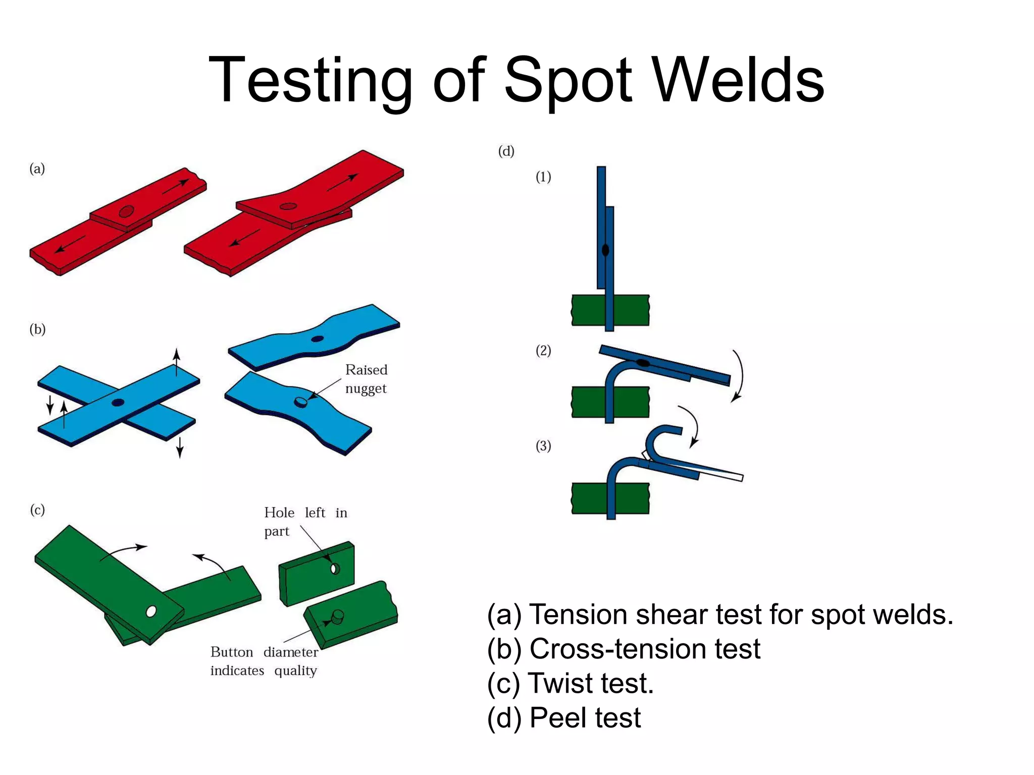
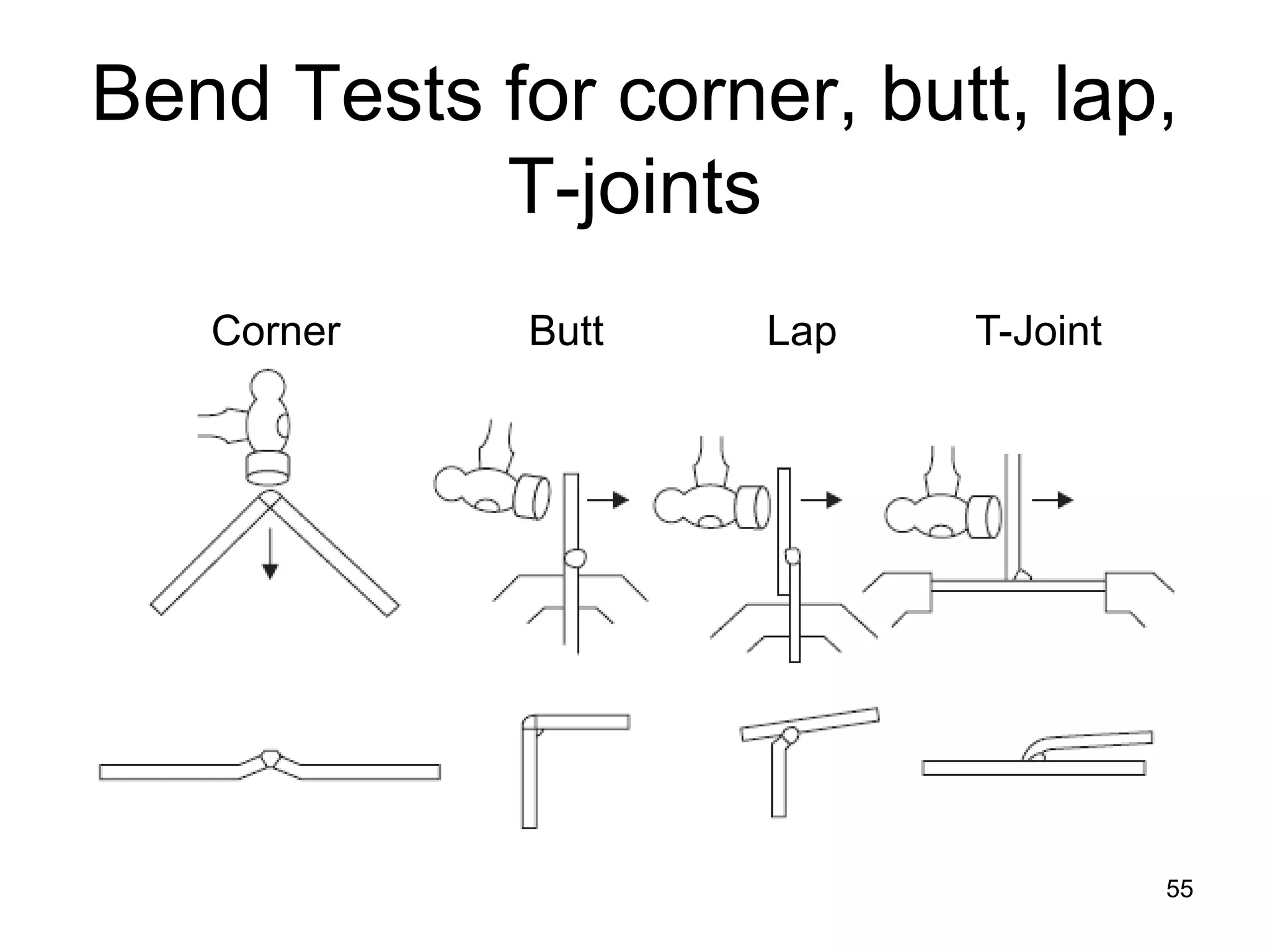
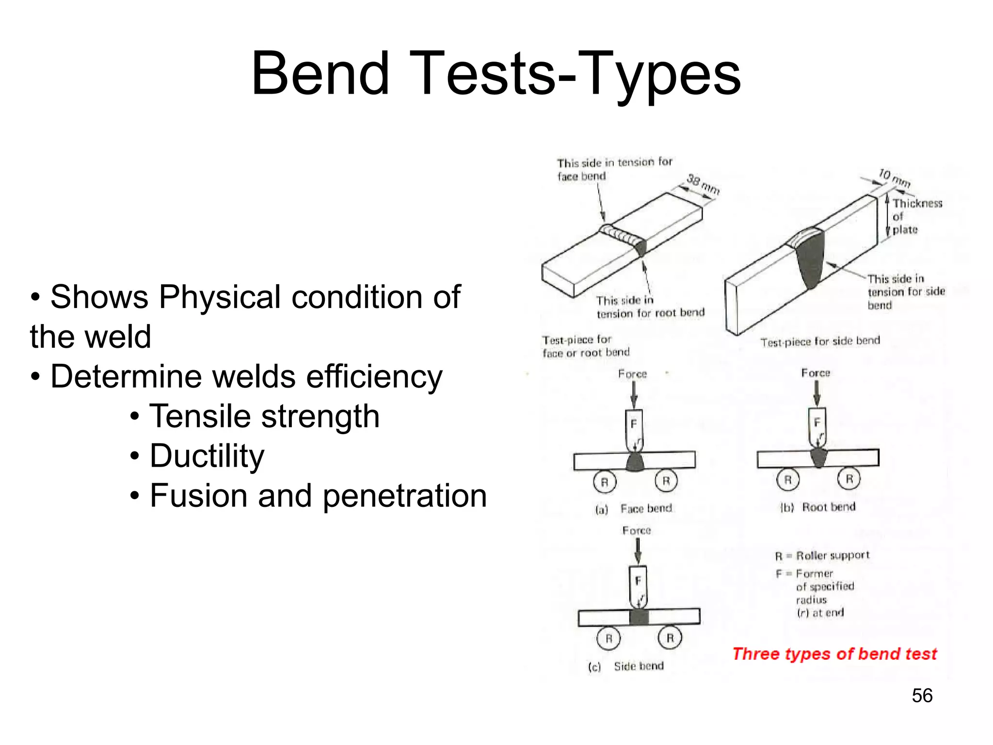

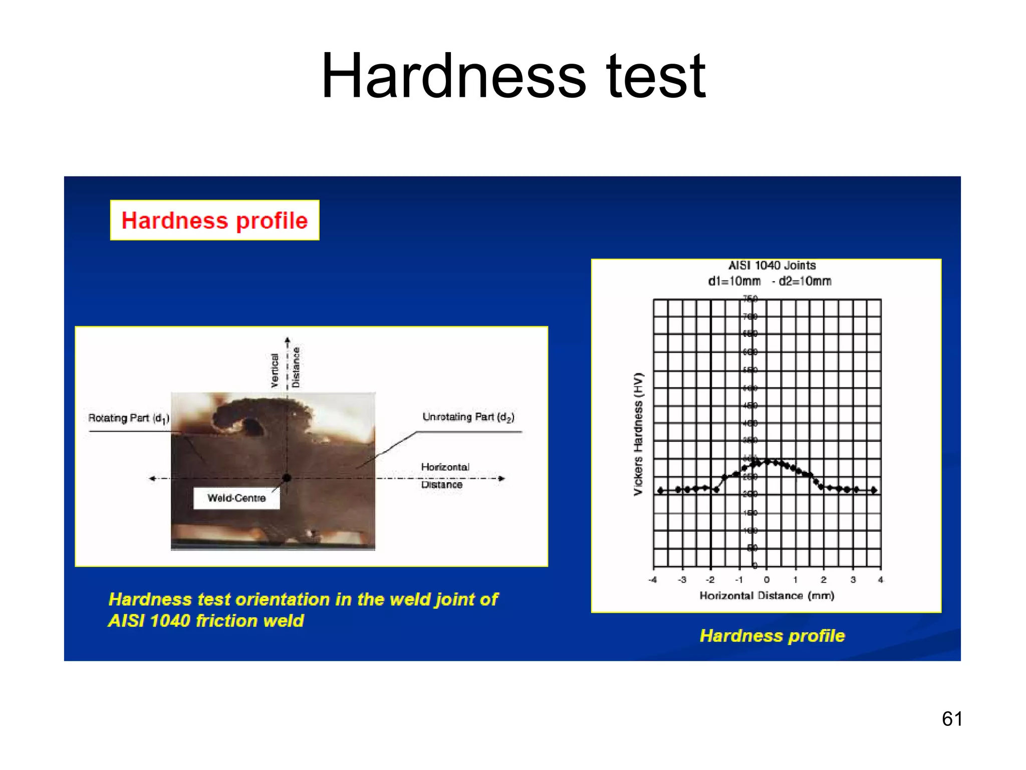
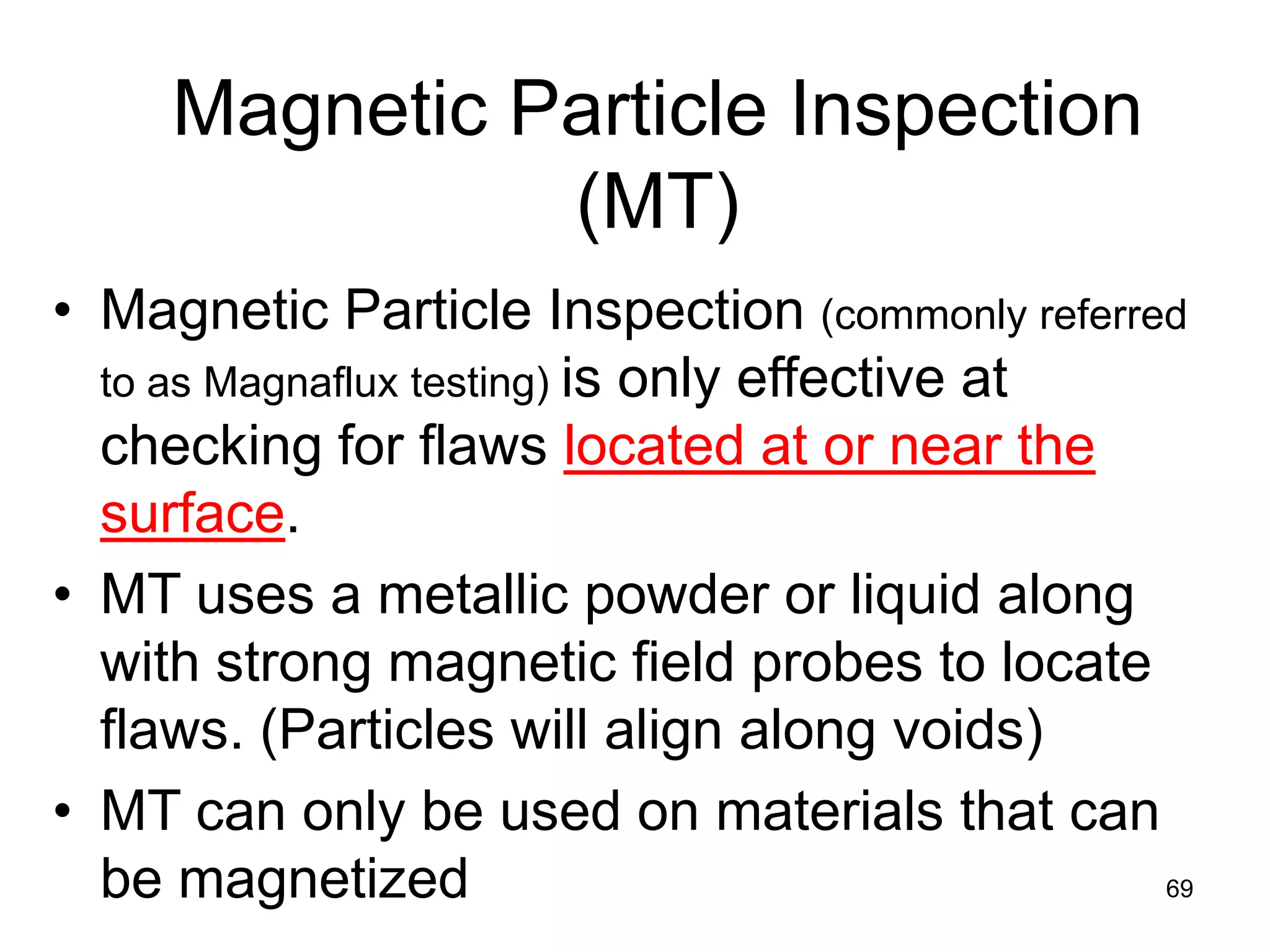
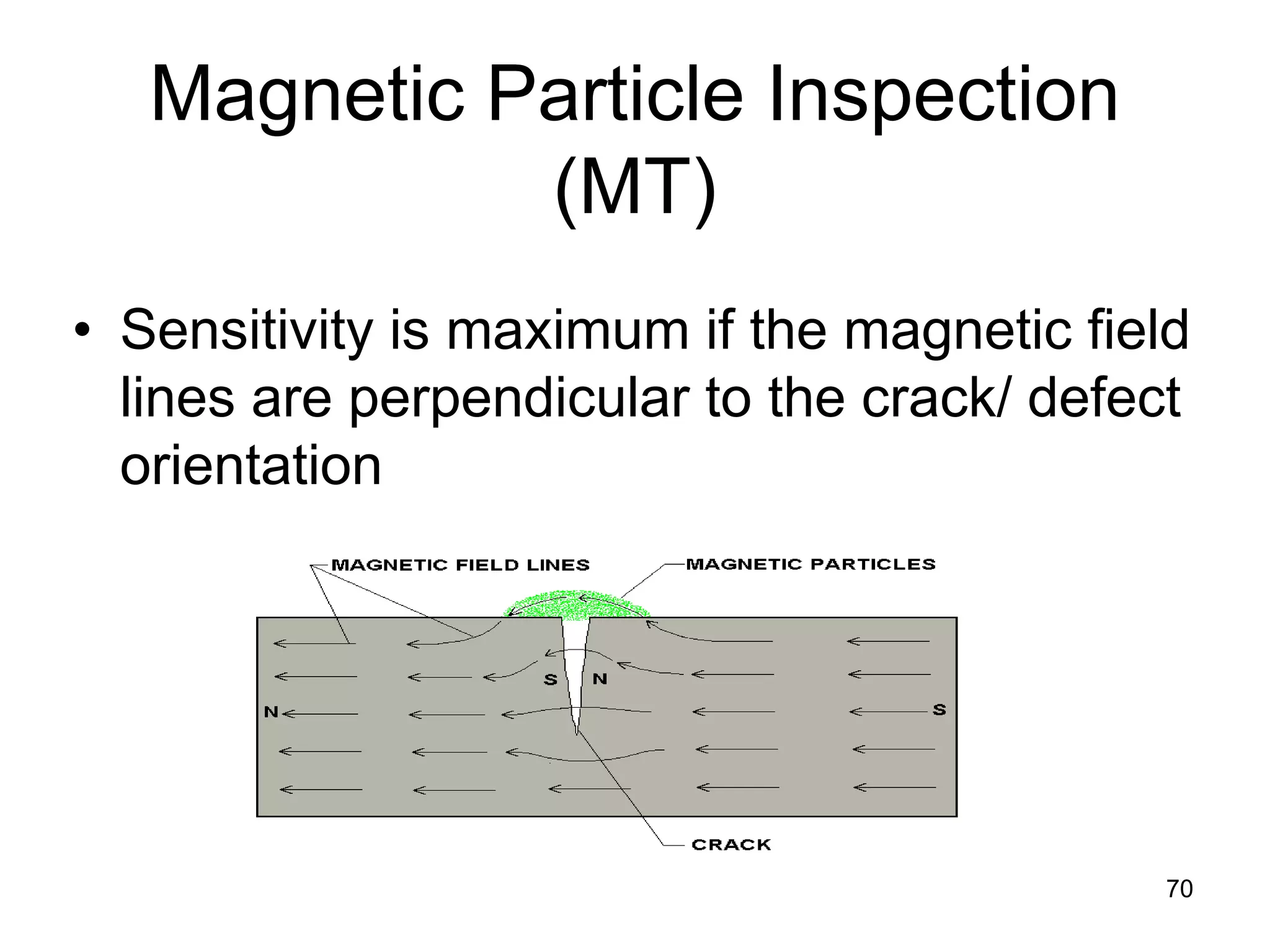
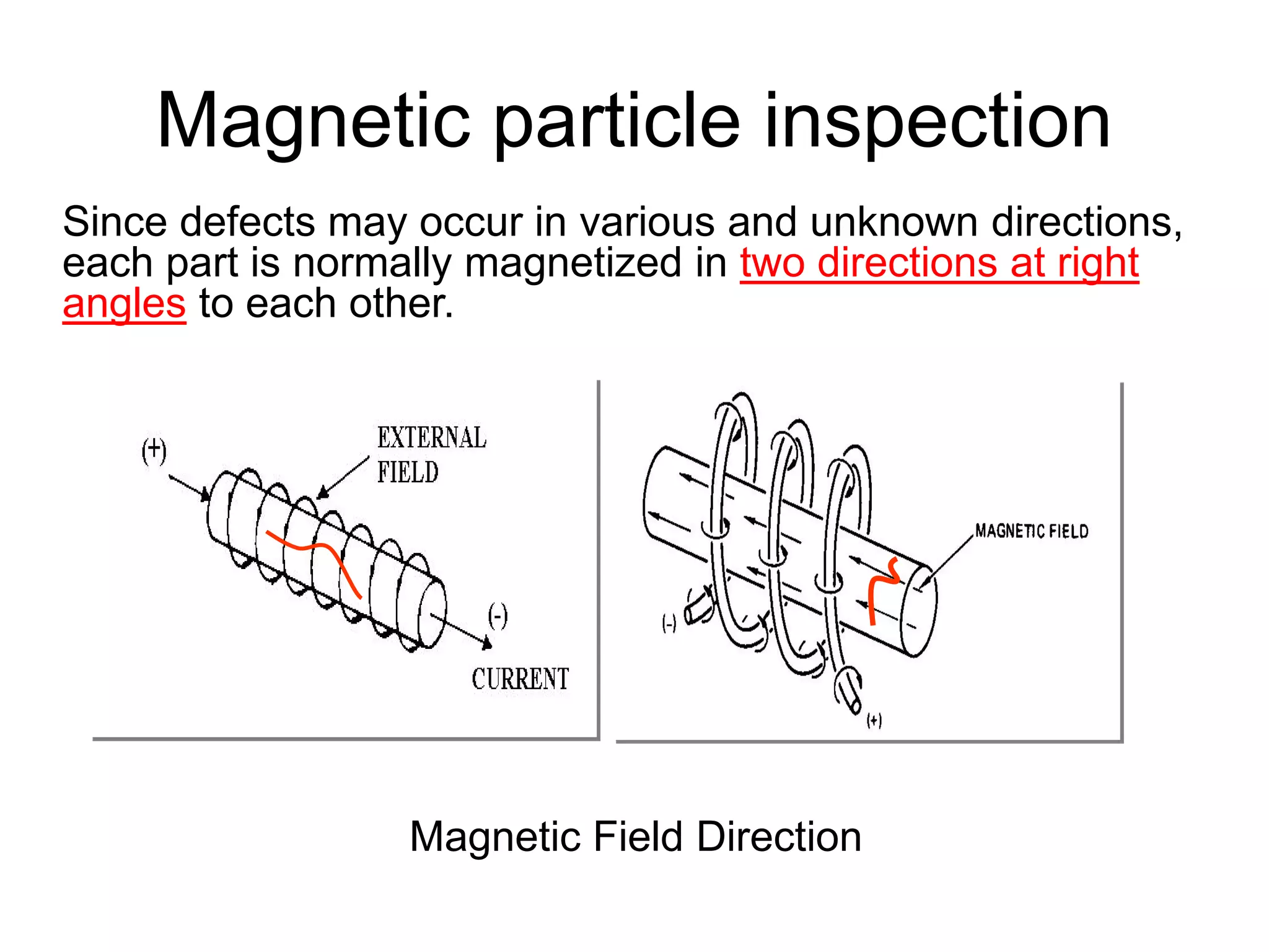
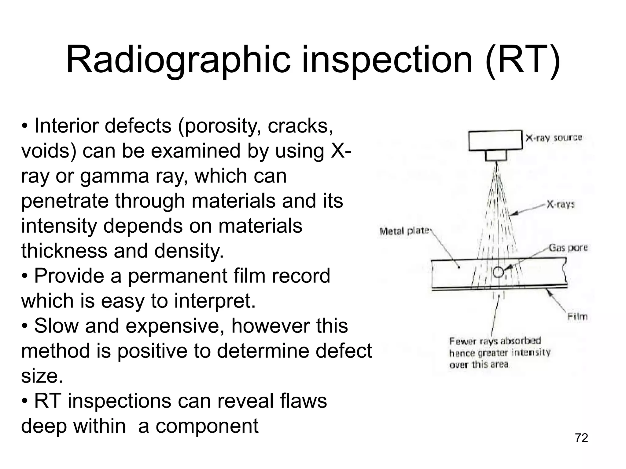
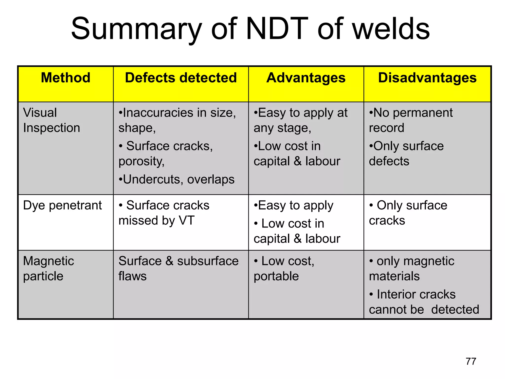
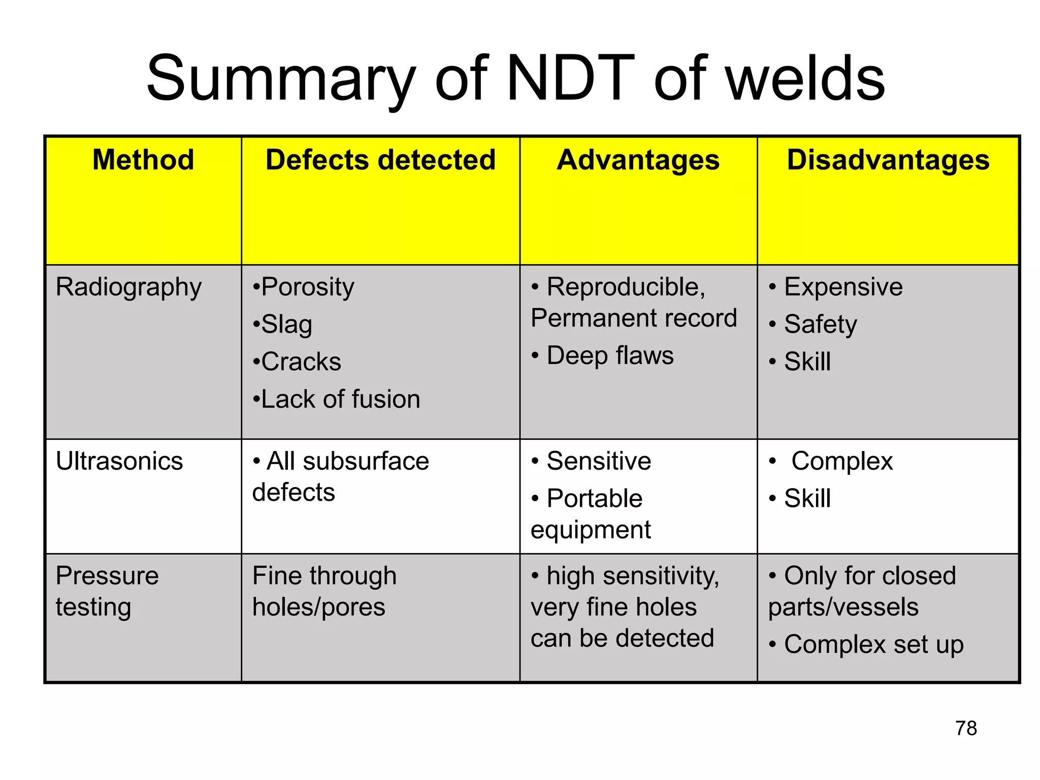


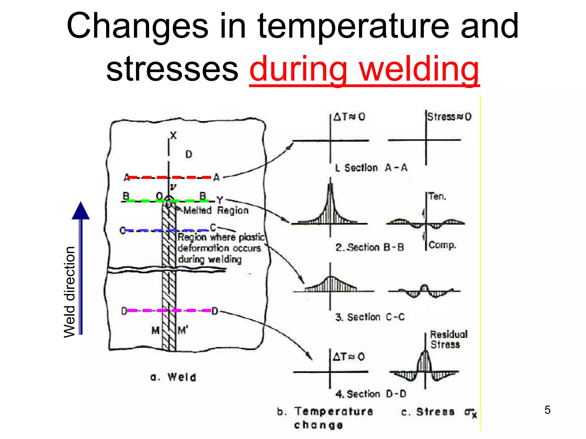
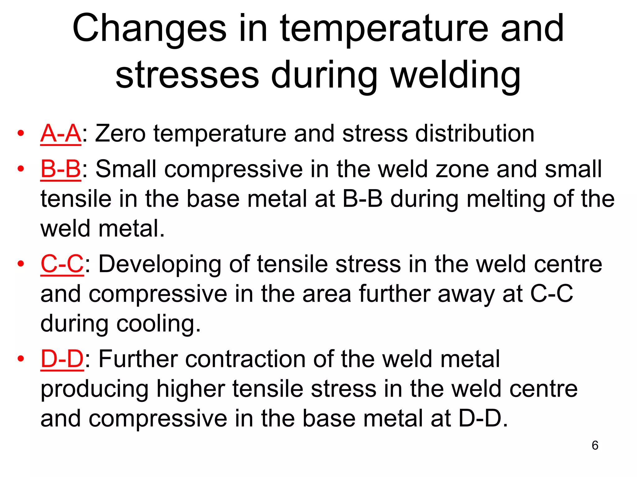
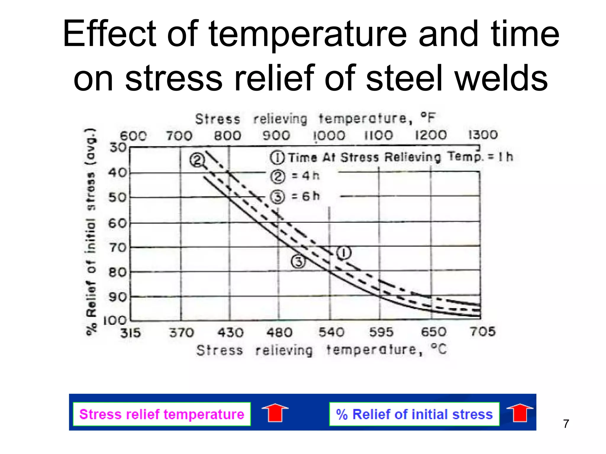
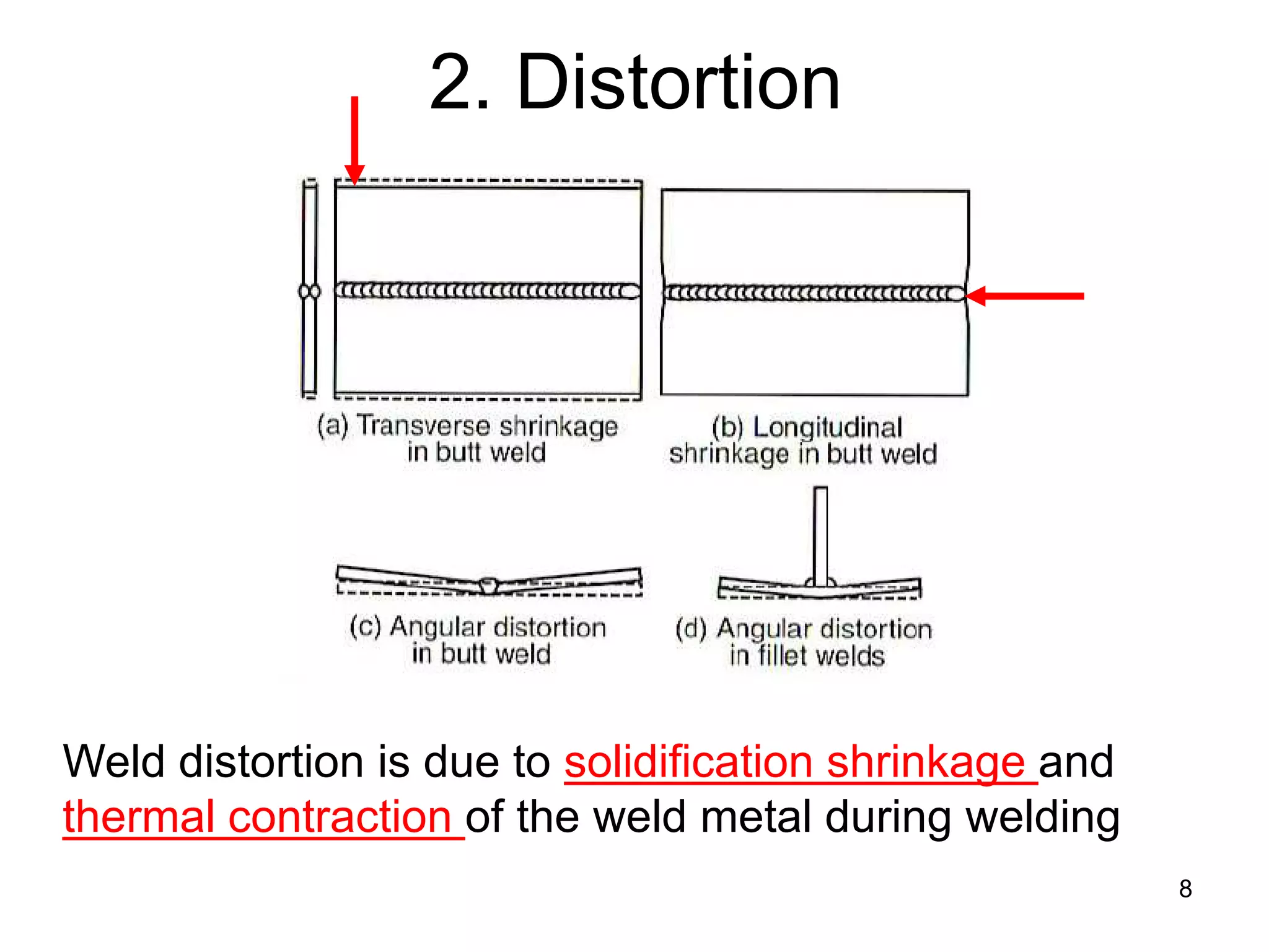
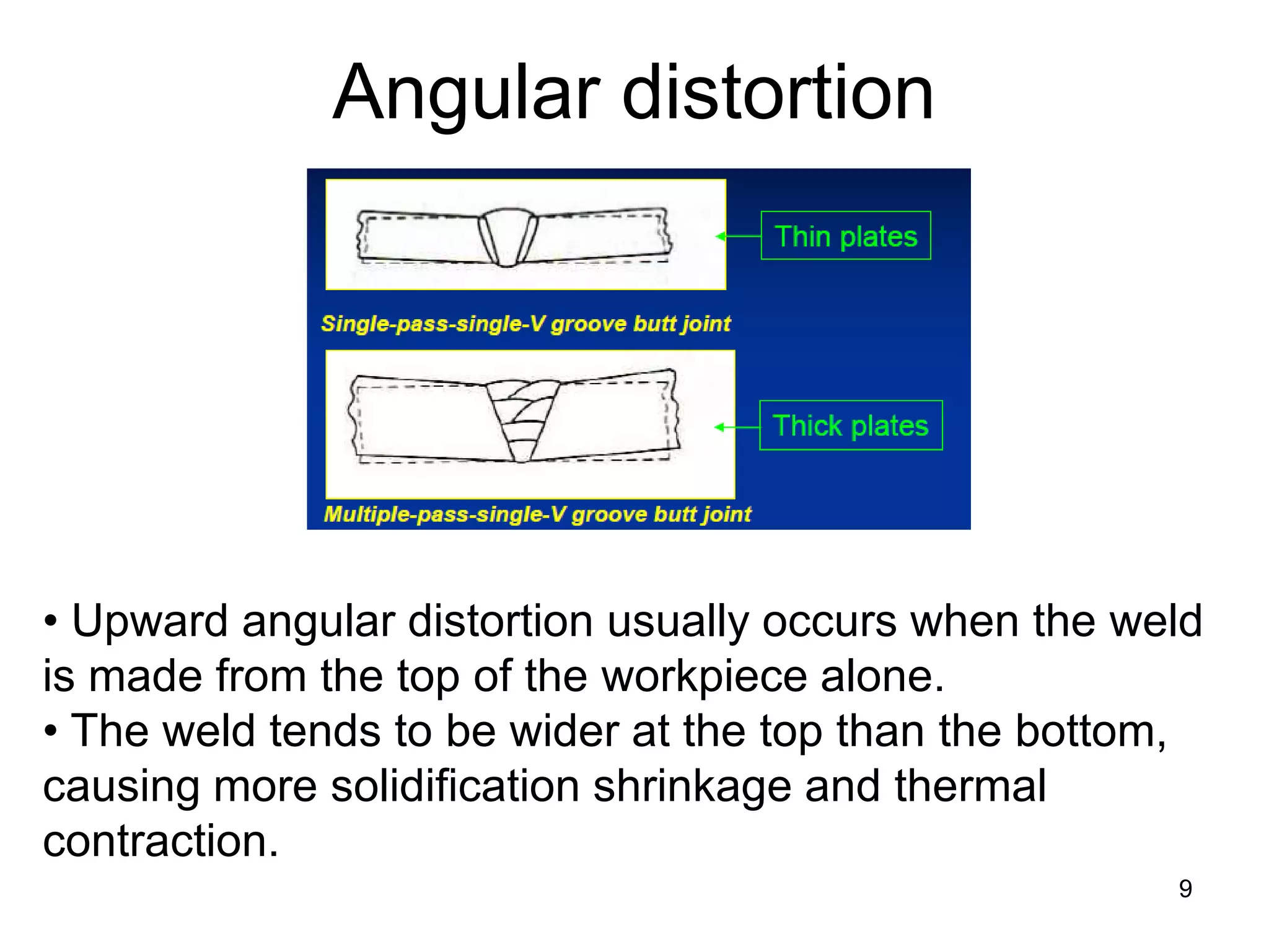
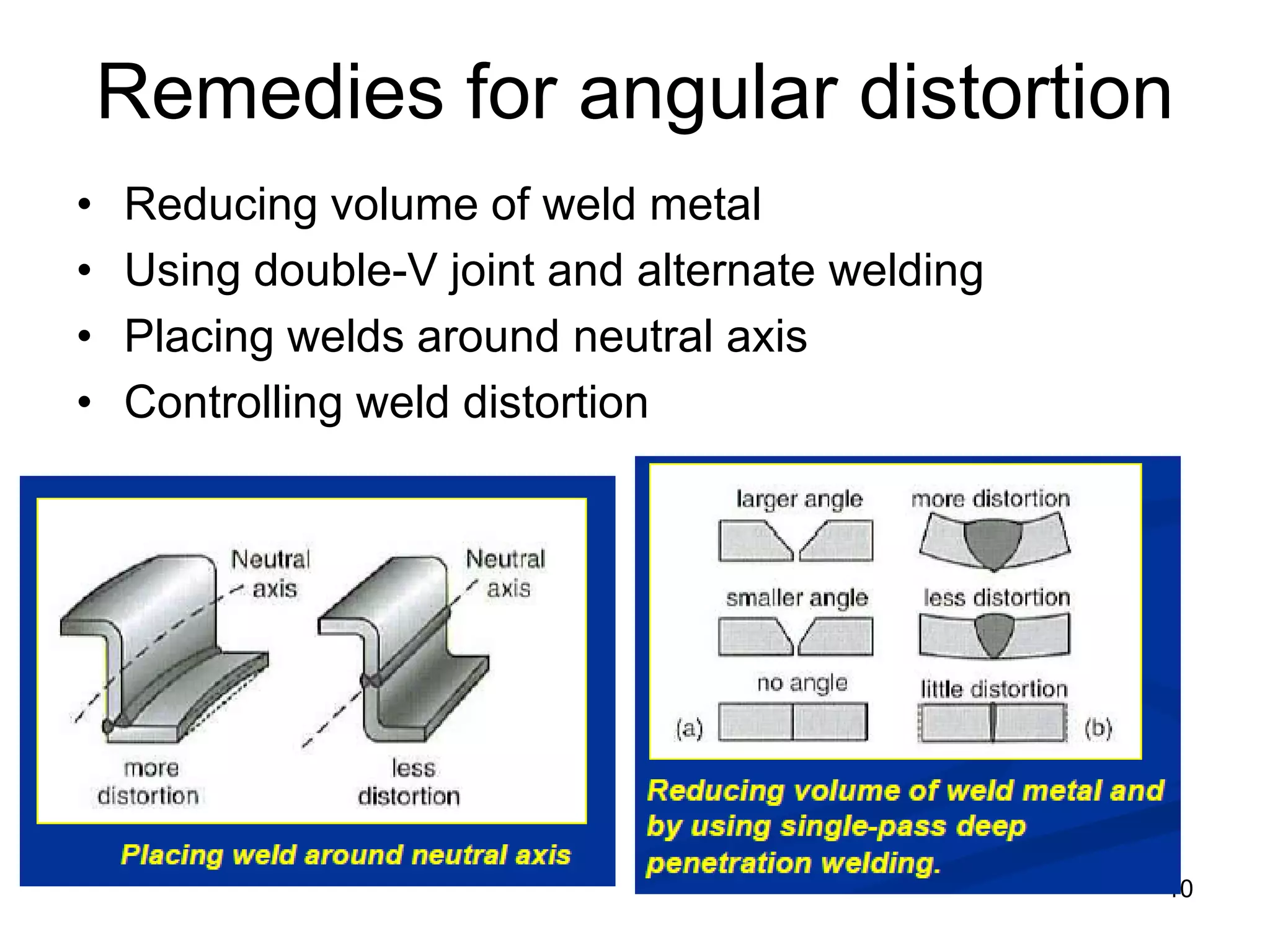
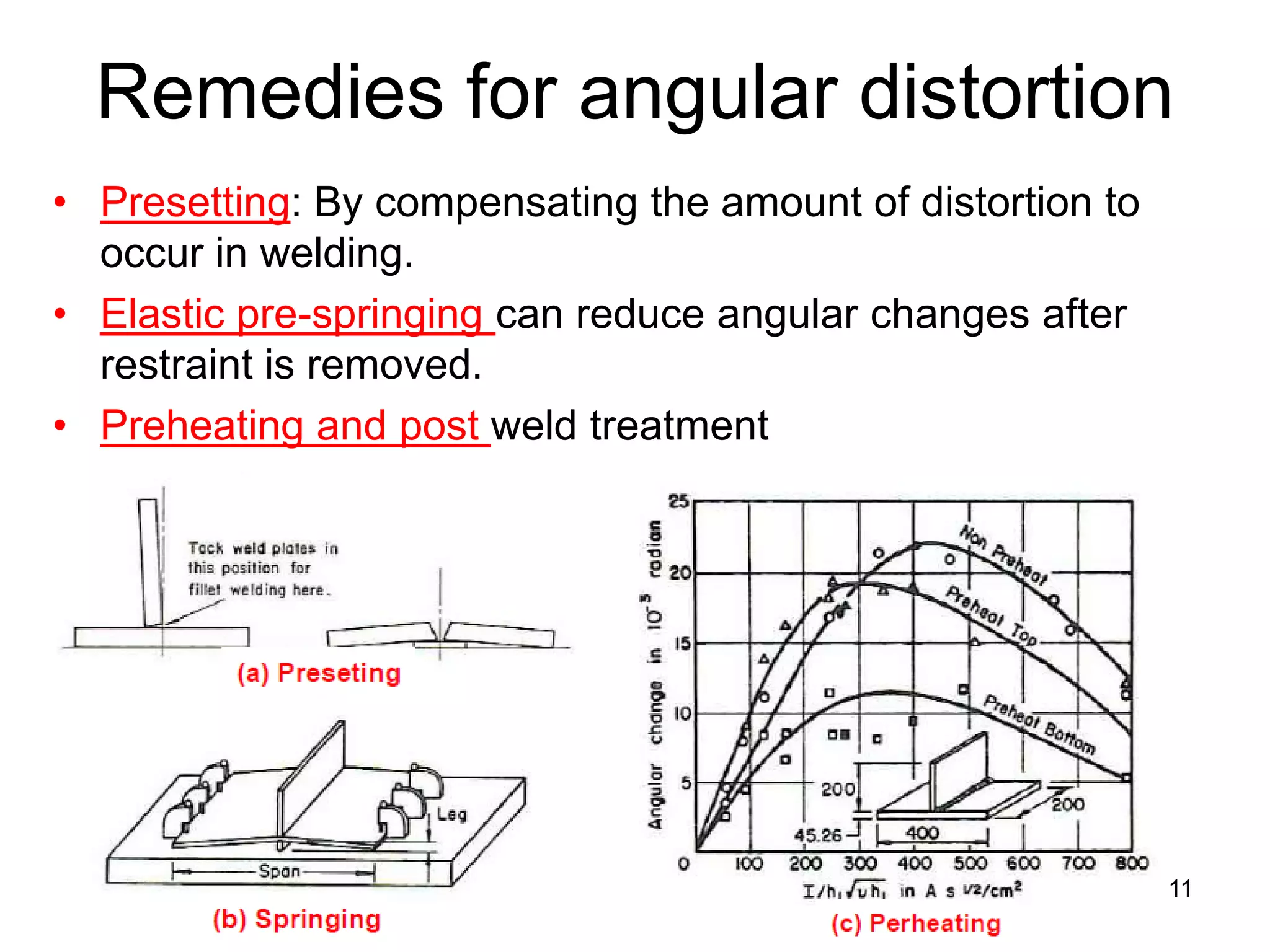
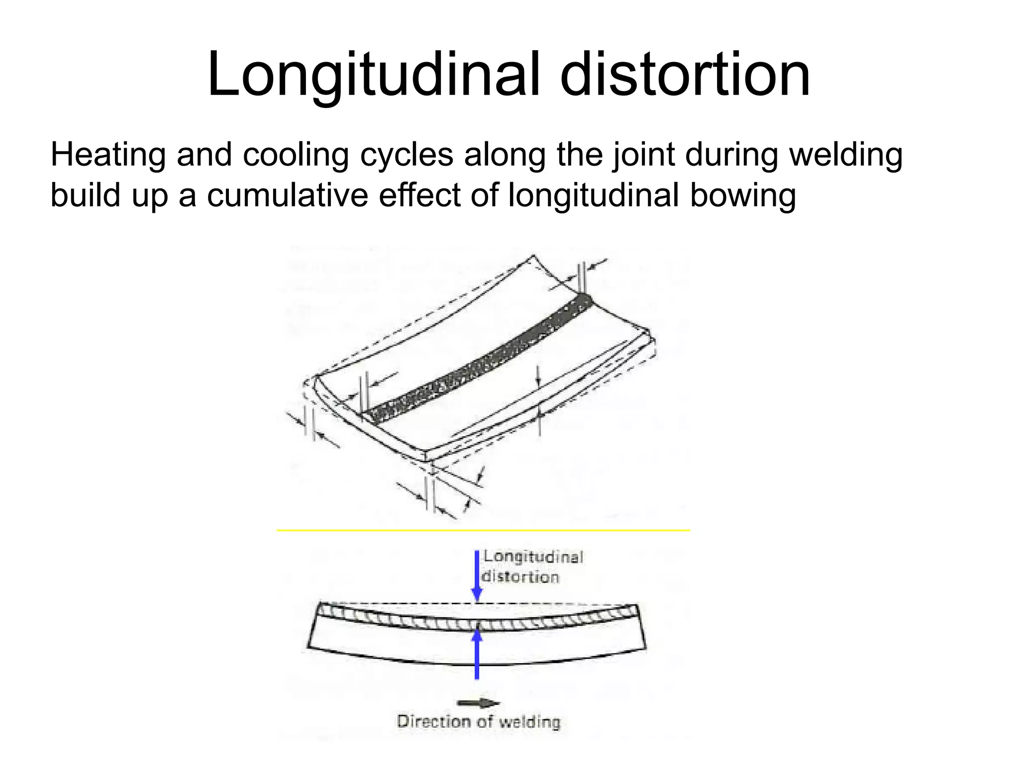
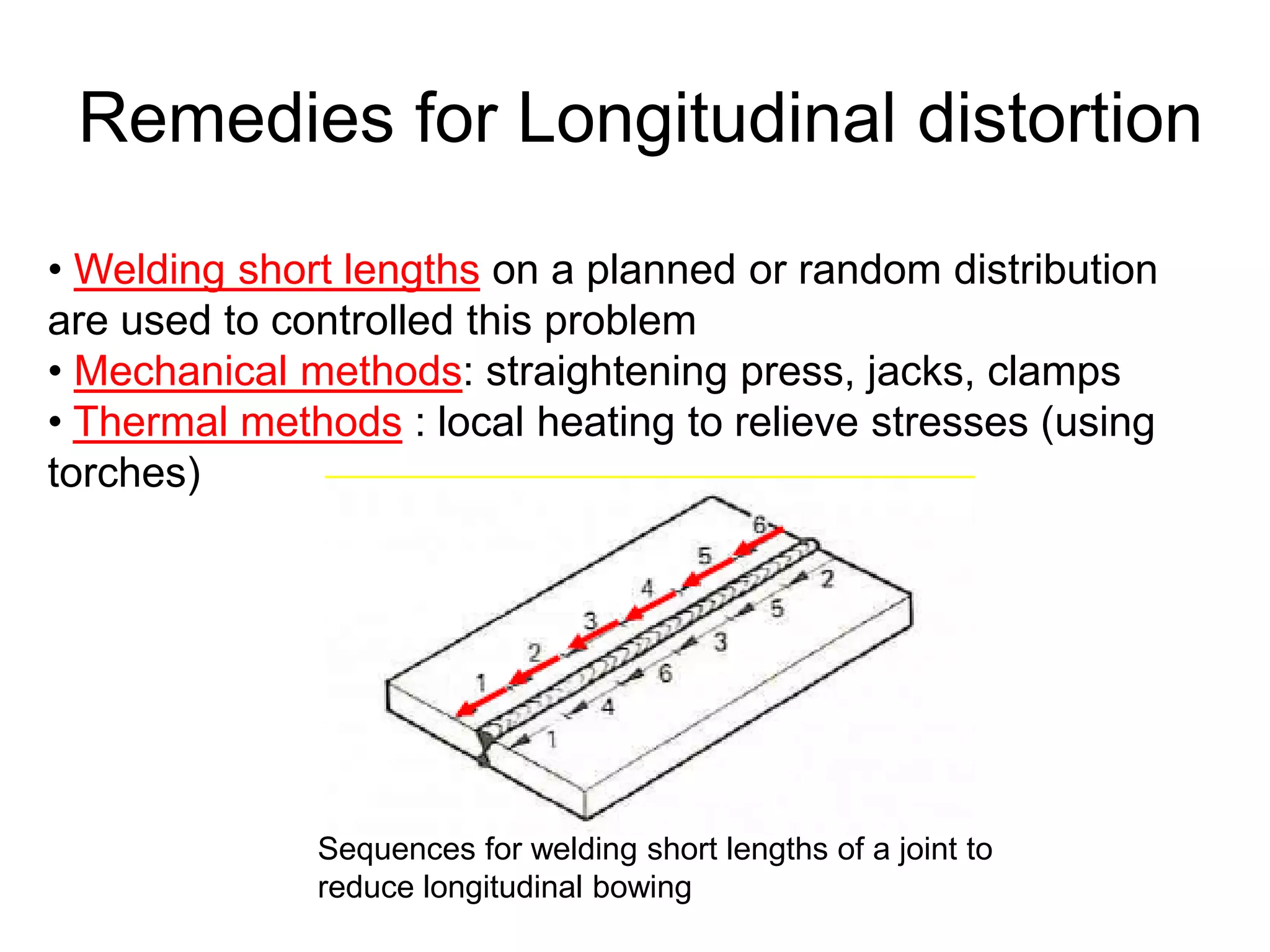
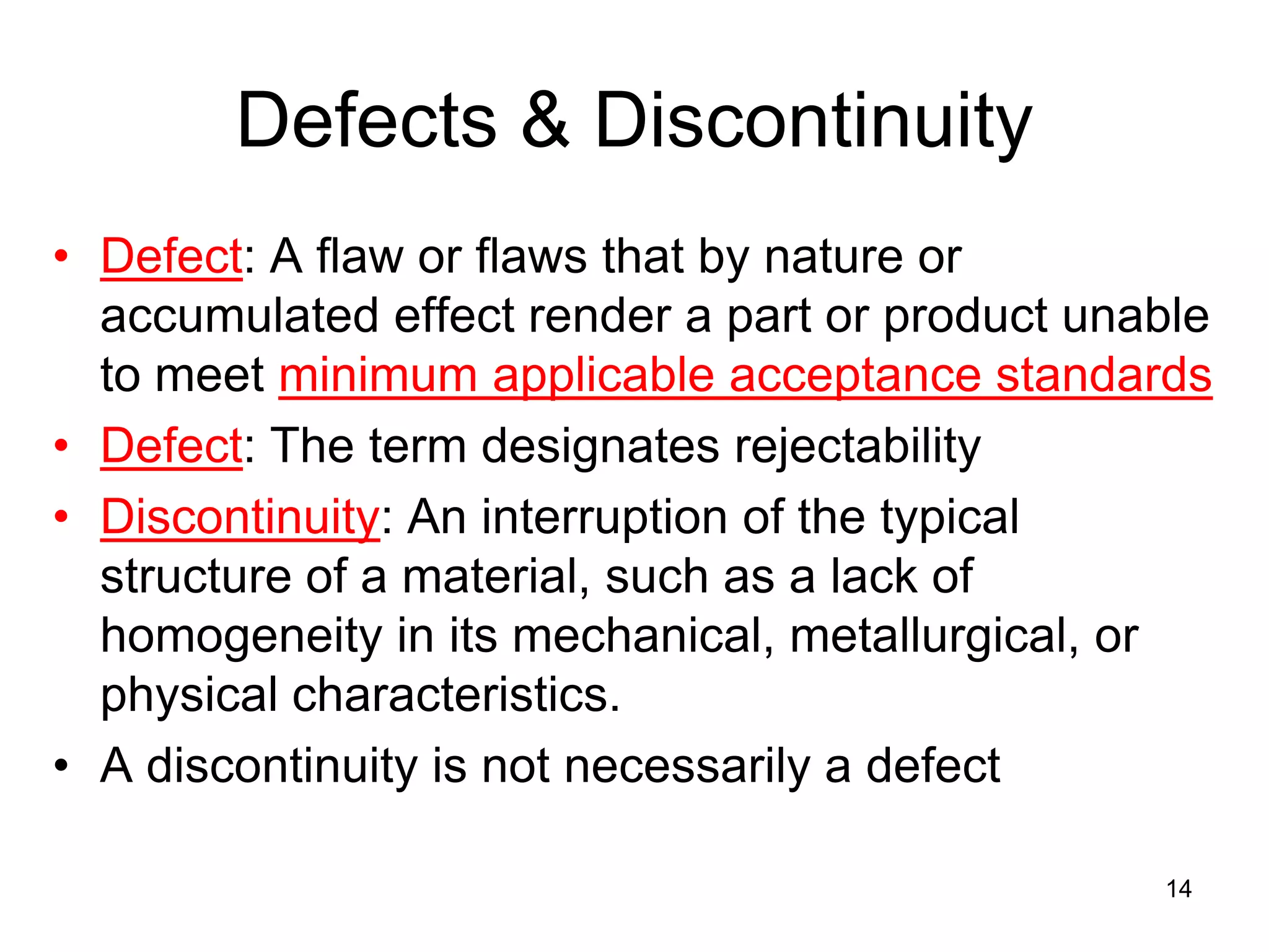
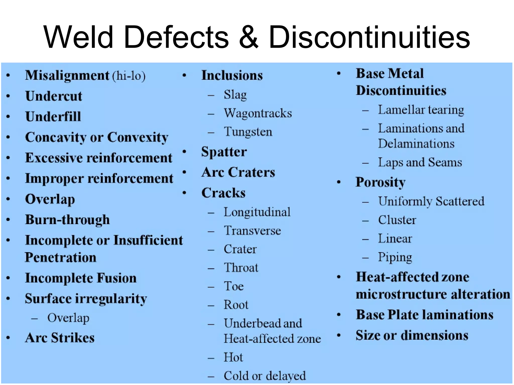
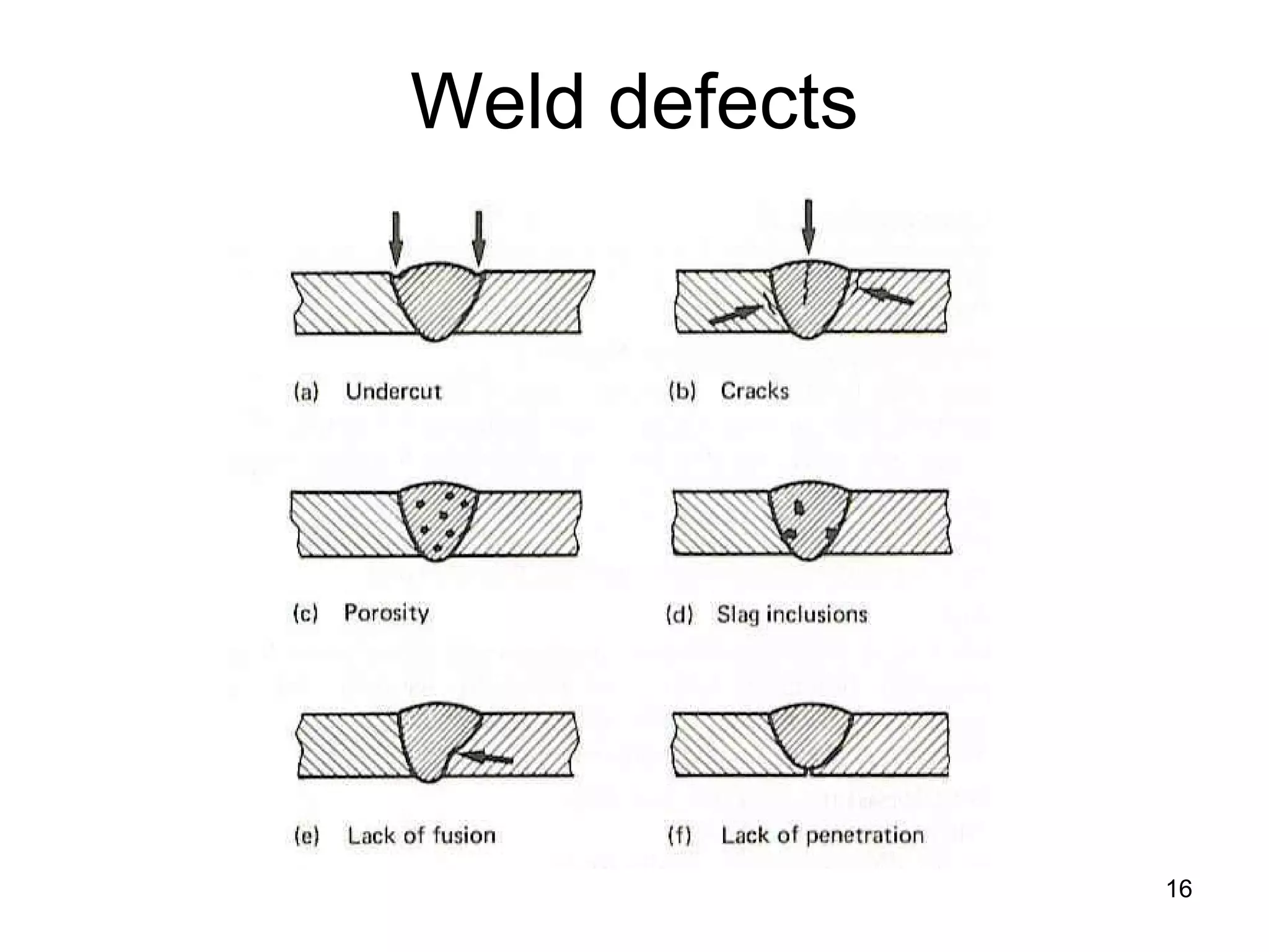
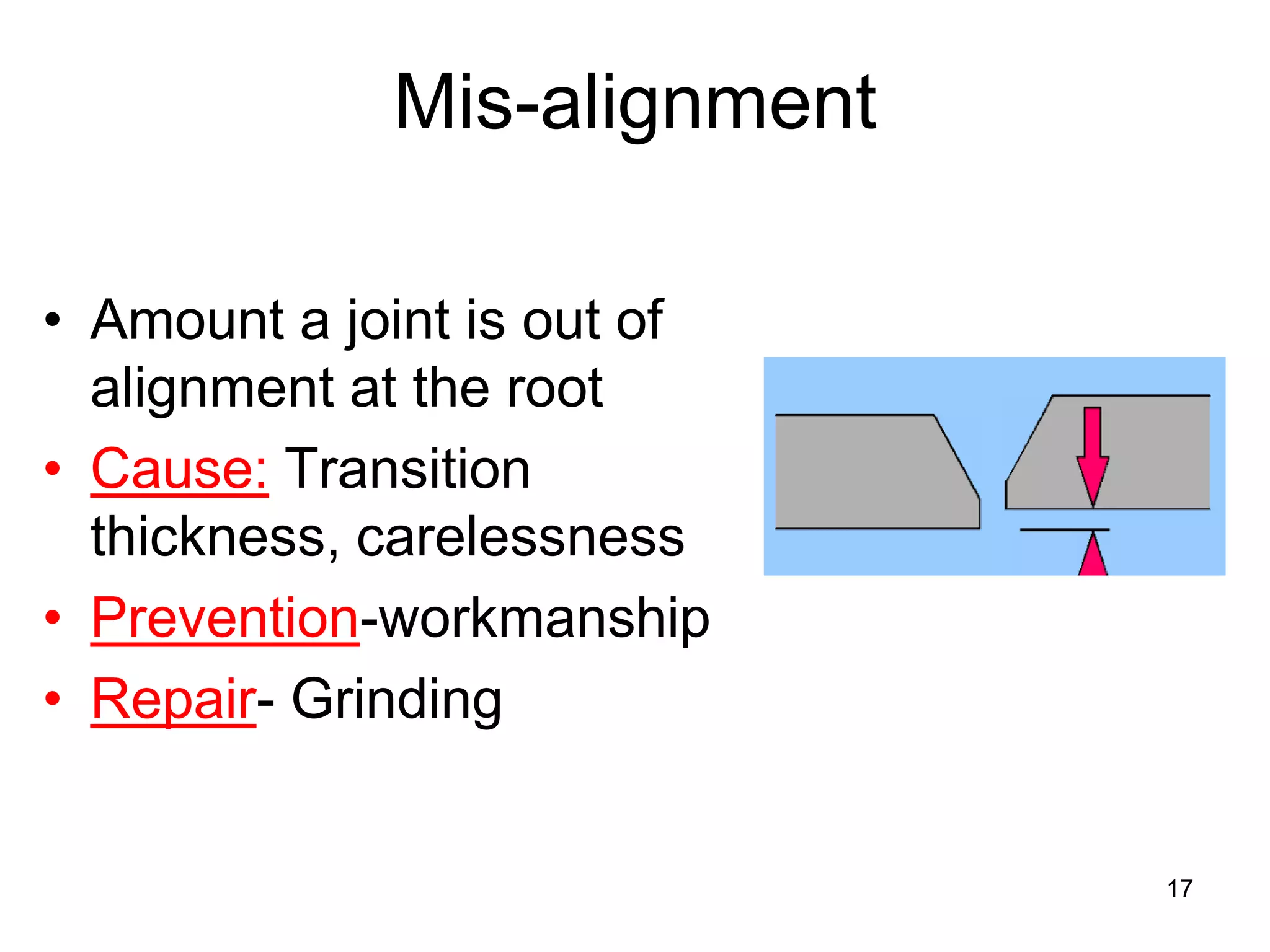
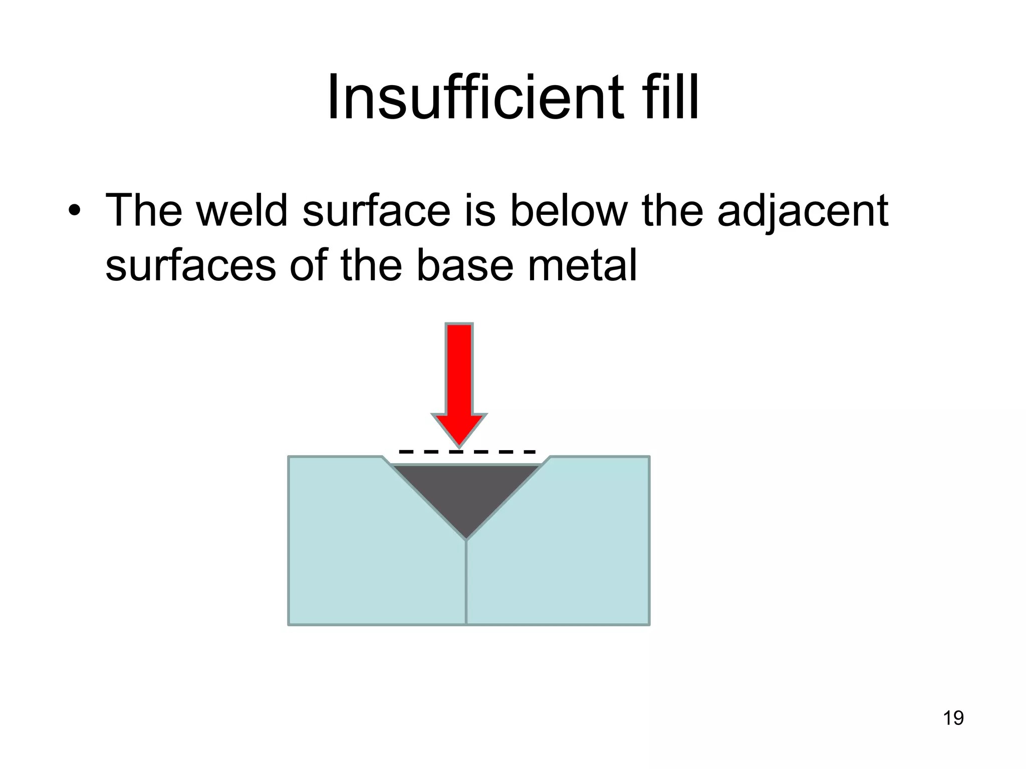
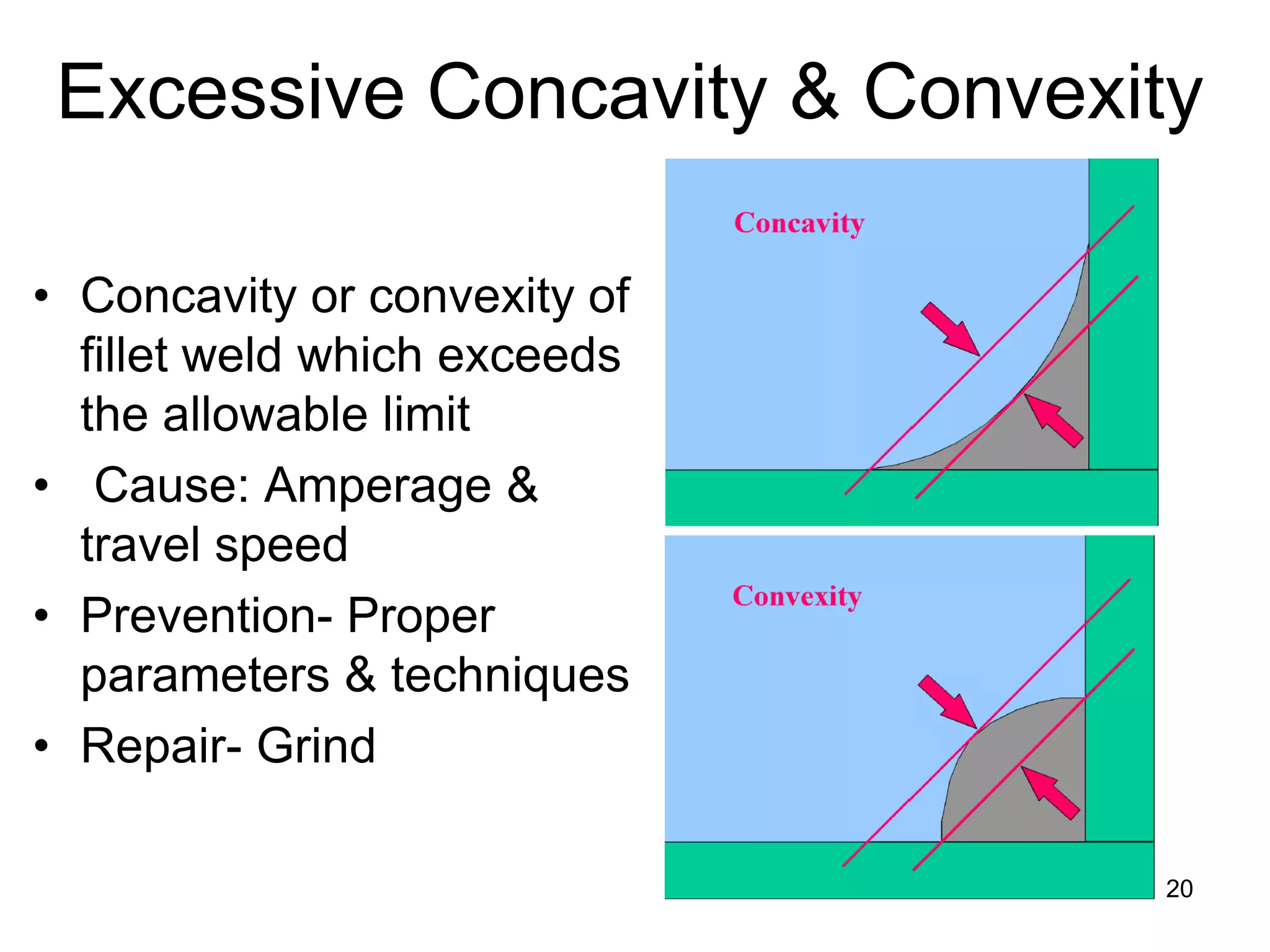
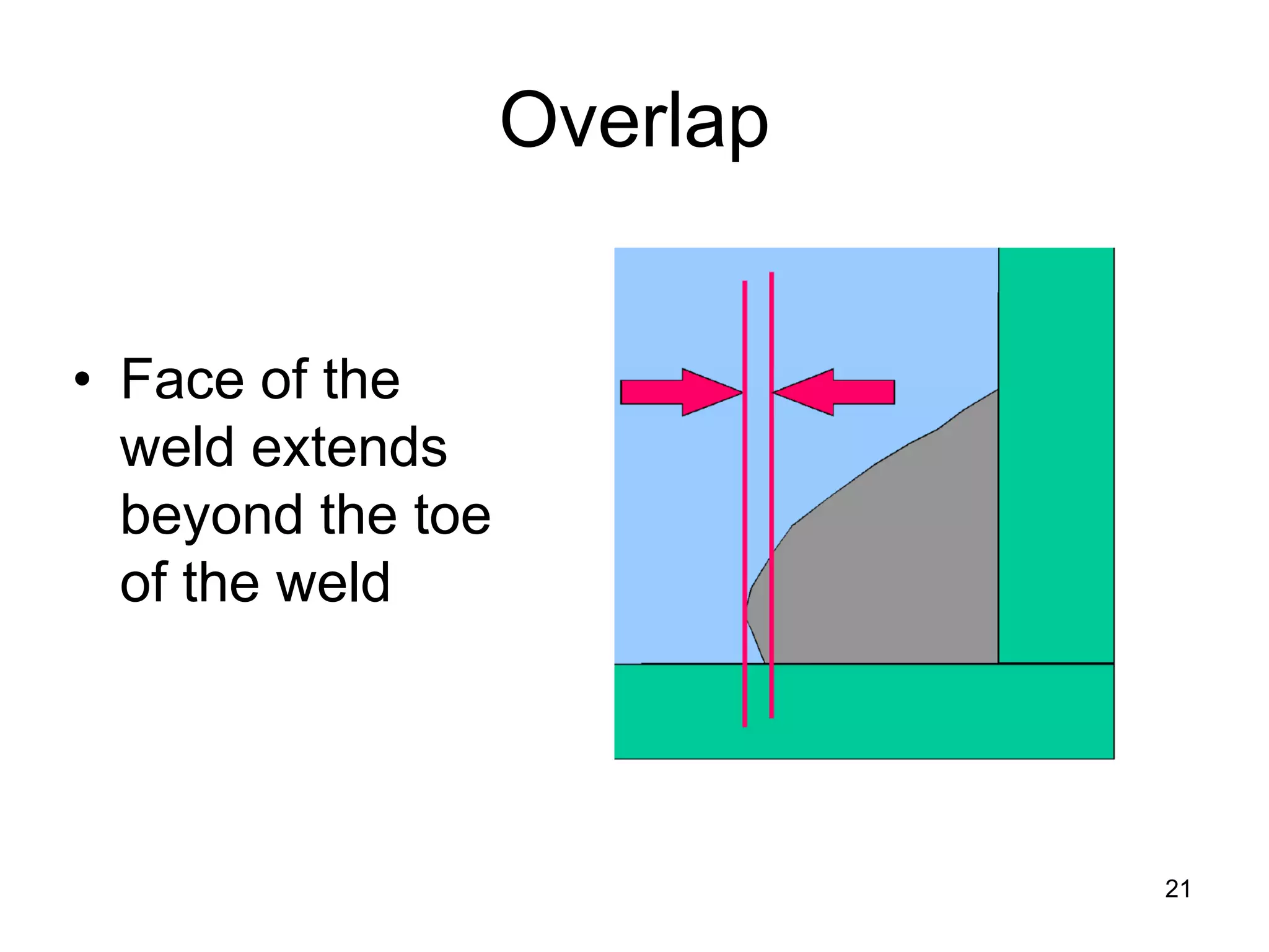
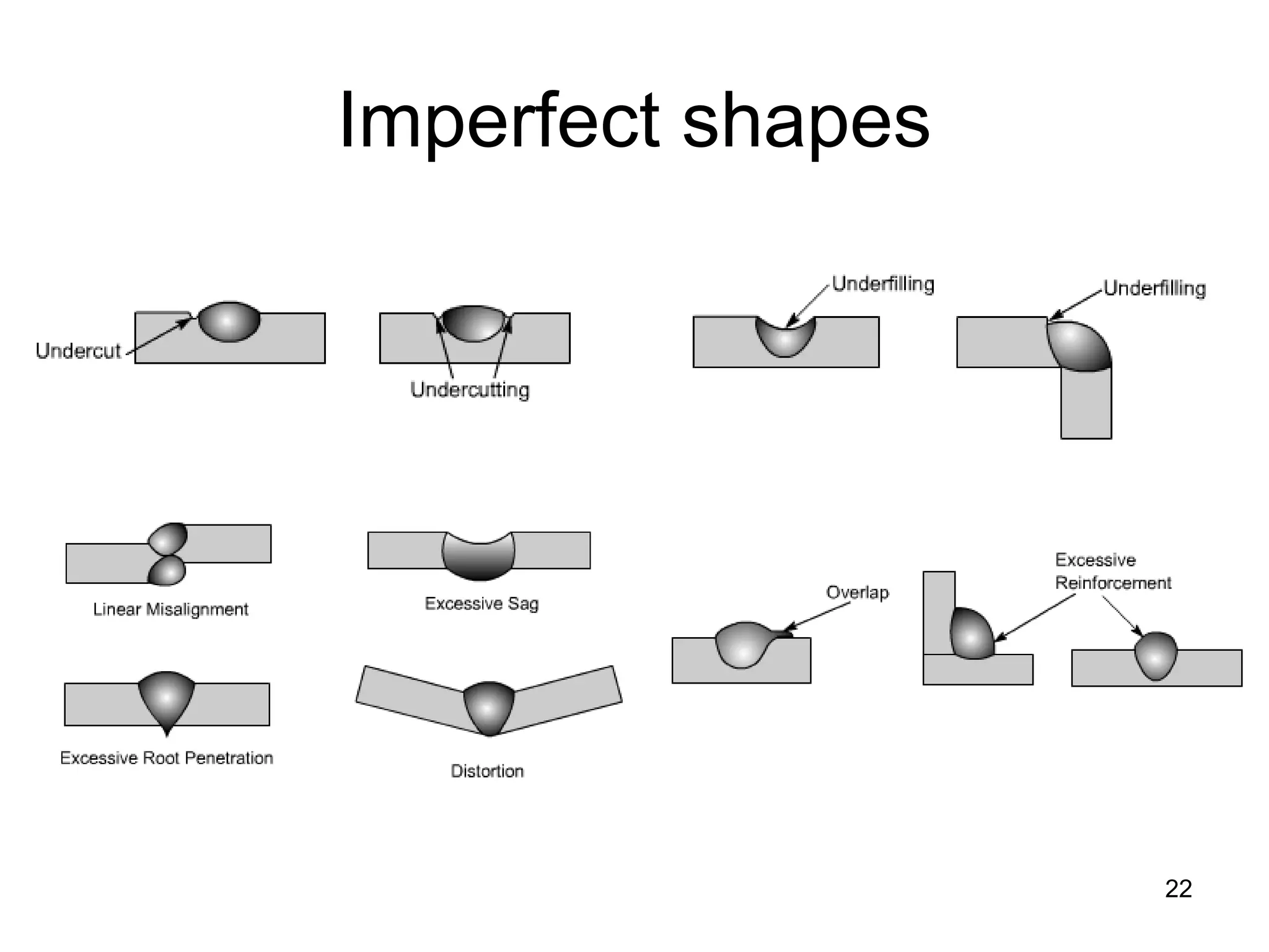
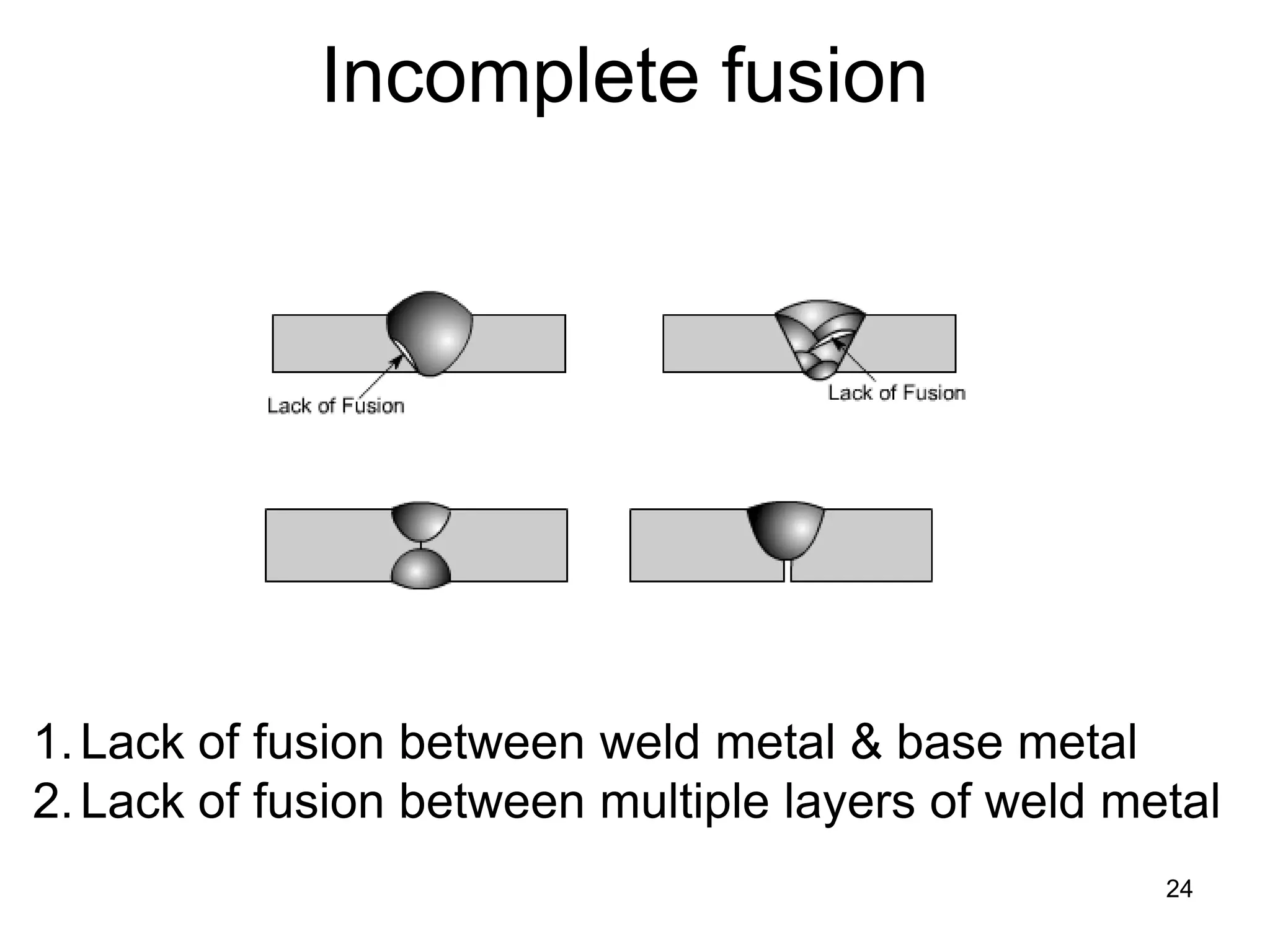
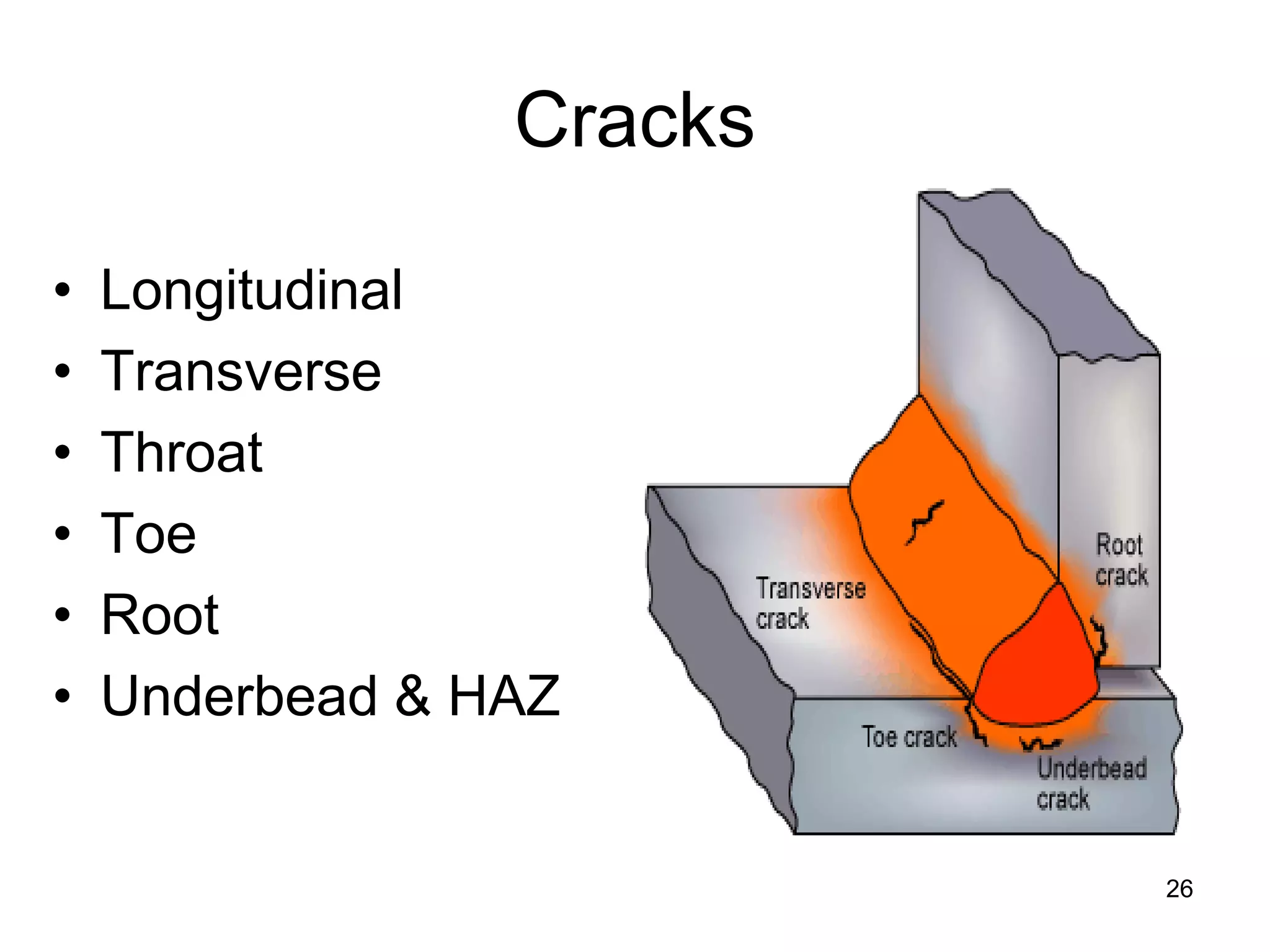
This document discusses various weld defects including geometric defects like misalignment and metallurgical defects like cracks, porosity, and embrittlement reactions. It explains the causes and remedies for different types of defects such as angular distortion, longitudinal distortion, incomplete fusion, cracks, and porosity. The document also covers residual stresses during welding, gas dissolution and solid solution hardening, hydrogen effects including hydrogen embrittlement and cracking, and common weld testing methods like tension tests, bend tests, hardness tests, and non-destructive tests including visual inspection, liquid penetrant, magnetic particle, x-ray and ultrasonic testing.


