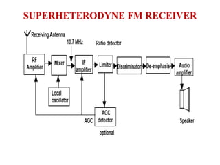
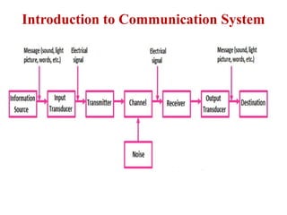
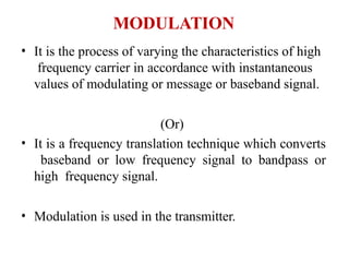
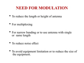
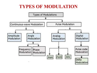
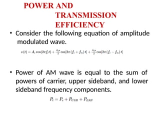
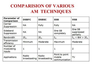
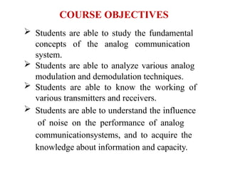
The document outlines a course on analog communication systems, focusing on amplitude and angle modulation, demodulation techniques, radio receivers, and noise analysis. It specifies objectives and outcomes for students, including the ability to analyze various modulation schemes, compute communication system parameters, and understand the impact of noise. The content is divided into multiple units covering topics like amplitude modulation, double sideband suppression, frequency modulation, and methods of multiplexing within the context of information theory.


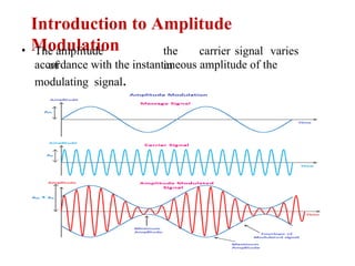
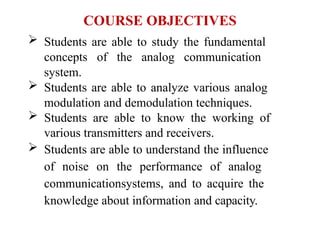
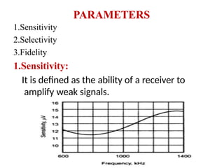
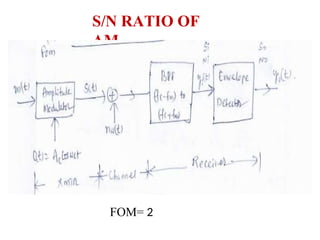
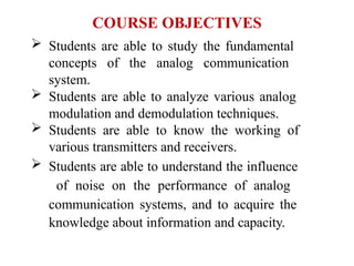
![SINGLE TONE
AM
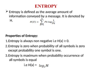
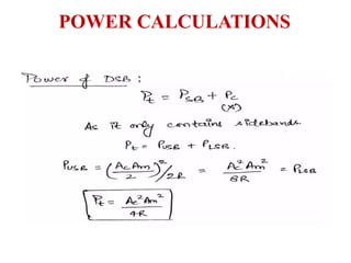
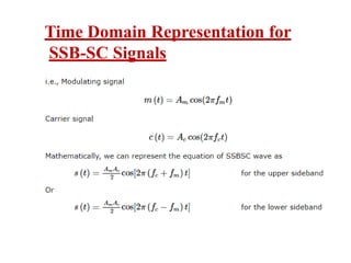
• Thestandard equation for
amplitude modulated signal is expressed as,
S(t)= Ac Cos2πfct[1+ma(Cos2πfmt)]
Where, ma = Am/Ac = Modulation
Index
Time Domain representation of AM:
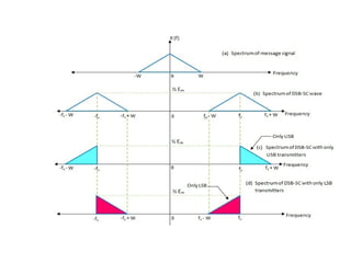
S(t)=AcCos2πfct+μAc/2Cos[2πfc+2πfm]t+μAc/2Cos[2πf
c-2πfm]t
I term: Carrier signal with amplitude Ac and frequency
fc.
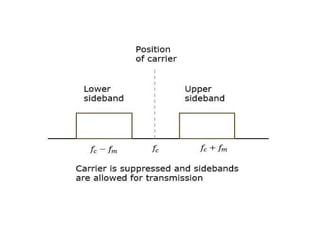
II. term: Amplitude= μAc/2, frequency= fc+fm ,
Upper sideband frequency
III.term: Amplitude= μAc/2, frequency= fc-fm ,
Lower sideband frequency](https://image.slidesharecdn.com/analogcommunicationsppt-240915112657-9e27c304/85/ANALOG-COMMUNICATIONS-including-AM-FM-modulation-13-320.jpg)


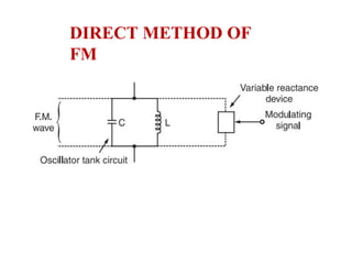
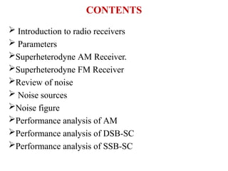
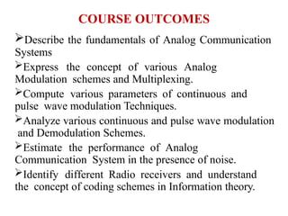
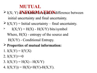
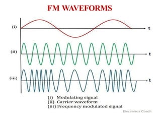
![FREQUENCY MODULATION
The process of varying frequency of the carrier in accordance with the
instantaneous values of the modulating signal.
Relation between angle and frequency :
Consider carrier signal c(t)= Ac Cos (wct+φ)
= Ac Cos (2πfct +φ)
Where, Wc = Carrier frequency
φ = Phase
C(t) = Ac Cos[ψ(t)], where,
ψ(t)= wct+φ
i.e Frequency can be obtained by derivating angle and angle can be
obtained
by integrating frequency.](https://image.slidesharecdn.com/analogcommunicationsppt-240915112657-9e27c304/85/ANALOG-COMMUNICATIONS-including-AM-FM-modulation-50-320.jpg)
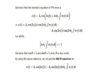
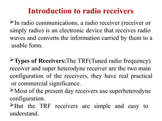
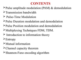
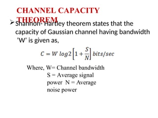
![FREQUENCY MODULATION
Frequency modulated signal can be written as,
AFM(t) = Ac Cos [ψi(t)] = Ac Cos [wct + kf m(t)dt]
ʃ
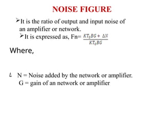
Frequency Deviation in FM:
The instantaneous
frequency, wi = wc + kf
m(t)](https://image.slidesharecdn.com/analogcommunicationsppt-240915112657-9e27c304/85/ANALOG-COMMUNICATIONS-including-AM-FM-modulation-51-320.jpg)
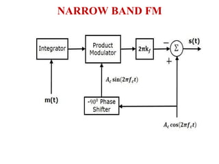
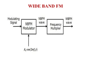
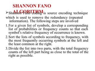
![Types of Frequency Modulation
FM (Frequency Modulation)
Narrowband FM (NBFM) Wideband FM (WBFM)
[When modulation index is small][When modulation index is large]](https://image.slidesharecdn.com/analogcommunicationsppt-240915112657-9e27c304/85/ANALOG-COMMUNICATIONS-including-AM-FM-modulation-53-320.jpg)