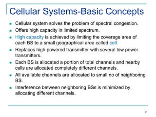
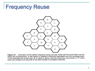
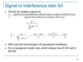
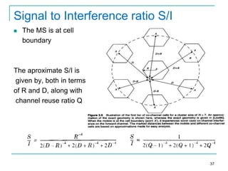
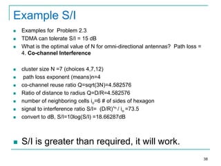
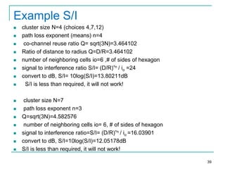
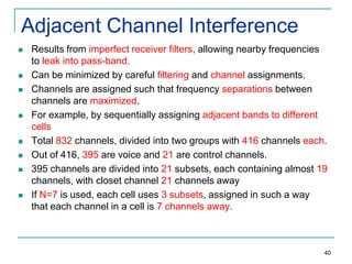
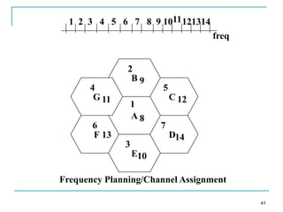
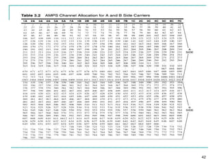
The document discusses the concept of frequency reuse in cellular networks. It explains that a limited radio spectrum is used to serve millions of subscribers by dividing the network coverage area into cells and reusing frequencies across spatially separated cells. Each cell is allocated a portion of the total available frequencies, and neighboring cells are assigned different frequencies to minimize interference. The frequency reuse factor is defined as the ratio of the minimum distance between co-channel cells to the cell radius. Larger frequency reuse factors provide better isolation between co-channel cells but reduce network capacity. The document also covers additional topics like different channel assignment strategies, handoff methods, interference calculation and optimization of frequency reuse networks.
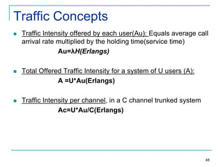
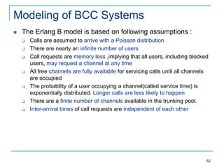
![Modeling of BCC Systems
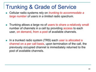
Erlang B formula is given by
Pr[blocking]= (AC/C ! )
where C is the number of trunked channels offered by a
trunked radio system and A is the total offered traffic.
53](https://image.slidesharecdn.com/chap3cellularconcepts-131217025114-phpapp01/85/cellular-concepts-in-wireless-communication-53-320.jpg)
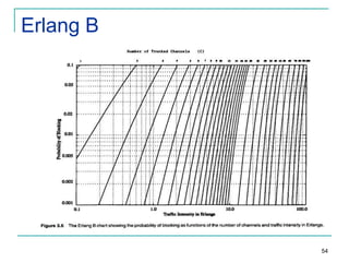
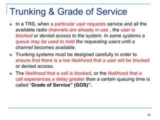
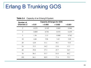
![BCC System Example
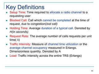
Assuming that each user in a system generates a traffic
intensity of 0.2 Erlangs, how many users can be supported for
0.1% probability of blocking in an Erlang B system for a
number of trunked channels equal to 60.
Solution 1:
System is an Erlang B
Au = 0.2 Erlangs
Pr [Blocking] = 0.001
C = 60 Channels
From the Erlang B figure, we see that
A ≈ 40 Erlangs
Therefore U=A/Au=40/0.02=2000users.
57](https://image.slidesharecdn.com/chap3cellularconcepts-131217025114-phpapp01/85/cellular-concepts-in-wireless-communication-57-320.jpg)
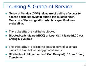
![Modeling of BCD Systems
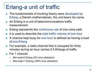
Probability that any caller is delayed in queue for a wait time
greater than t seconds is given as GOS of a BCD System
The probability of a call getting delayed for any period of time
greater than zero is
P[delayed call is forced to wait > t sec]=P[delayed] x Conditional
P[delay is >t sec]
Mathematically;
Pr[delay>t] = Pr [delay>0] Pr [delay>t| delay>0]
Where
P[delay>t| delay>0]= e(-(C-A)t/H)
Pr[delay>t] = Pr [delay>0] e(-(C-A)t/H)
where C = total number of channels, t =delay time of interest, H=average
duration of call
61](https://image.slidesharecdn.com/chap3cellularconcepts-131217025114-phpapp01/85/cellular-concepts-in-wireless-communication-61-320.jpg)
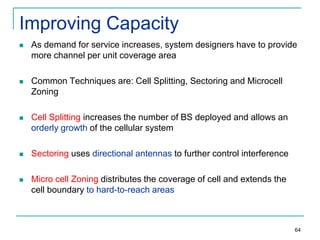
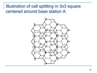
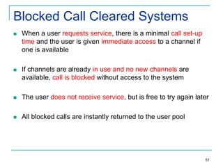
![Cell Splitting-Power Issues
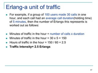
Suppose the cell radius of new cells is reduced by half
What is the required transmit power for these new cells??
Pr[at old cell boundary]=Pt1R-n
Pr[at new cell boundary]= Pt2(R/2) –n
where Pt1and Pt2are the transmit powers of the larger and
smaller cell base stations respectively, and n is the path loss
exponent.
So,
Pt2= Pt1/2n
If we take n=3 and the received powers equal to each other, then
Pt2=Pt1/8
In other words, the transmit power must be reduced by 9dB in order
to fill in the original coverage area while maintaining the S/I
requirement
68](https://image.slidesharecdn.com/chap3cellularconcepts-131217025114-phpapp01/85/cellular-concepts-in-wireless-communication-68-320.jpg)