Downloaded 159 times


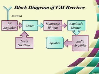
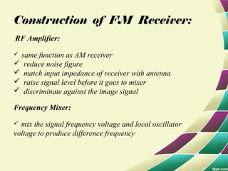


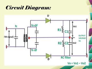
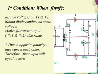
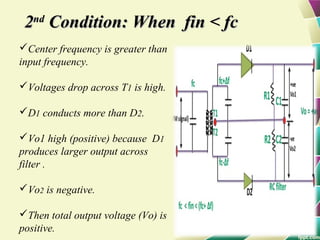
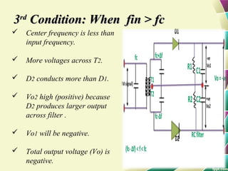

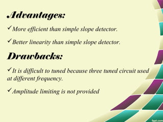


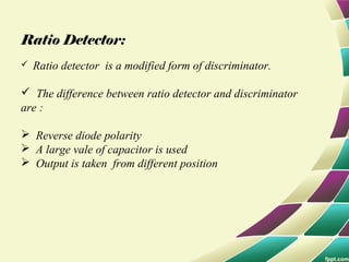

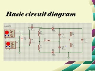
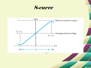


This document provides information on FM modulation and FM receivers. It discusses the key components of an FM receiver including the RF amplifier, mixer, local oscillator, IF amplifier, amplitude limiter, FM demodulator, de-emphasis circuit and audio amplifier. It then describes various FM demodulation techniques including the single tuned slope detector, balanced slope detector, Foster-Seeley discriminator, and ratio detector. For each technique, it provides the basic principles, circuit diagrams and operating characteristics. The document is intended to inform readers about the technology behind FM receivers and different methods for demodulating an FM signal.


